A bench style cabinet subwoofer 2x15 closed

Hi, I'm planning a big subwoofer for my rather small home theater room. The room is 2,6x3,65x2,5m (9,5 m2) with low RT60. I watch movies and listen to music with moderae volume, so my main goal is to get fast and precise bass. The main speakers are concentrics in closed cabinets and they go linearly down to 60Hz, the sub,s xo is 80Hz and I use a Hypex DS plate amp.

The idea is to make a 400-450L closed cabinet for two 15" elements. The cabinet must have the form of a closed bench and it will sit below the screen right next to the wall and from corner to corner.

The elements could be Dayton DCS380-4 (VAS 233L) and they are cheap. Perhaps later on I can update to RSS390

Whic cabinet style do you prefer and why? 1) woofers down or 2) woofers on vertical slots
Pictures here: (the 400L version shown without the top panel)

Attachments

  • sub450 kuva.jpg
    sub450 kuva.jpg
    18.3 KB · Views: 1,384
  • sub400 kuva.png
    sub400 kuva.png
    20.9 KB · Views: 1,343

Crossover component selection help

I'm about to rebuild the internal mid/high crossovers in my Magnepan 3.6Rs with better parts. I biamp, so I don't use the external crossover. All I'll be rebuilding is this. I'd like to keep the cost, excluding wire and connectors, to under $1000. If that's not possible or if there is significant improvement to be had by spending more, I can stretch the budget.

Since I don't know much about what caps and inductors sound good, I could use some help. I'd like to lean away from bright sounding parts since the system probably tilts slightly in that direction already. Parts that lean slightly toward lush or rich sounding would be preferred as long as they don't sacrifice necessary detail. Any size components are okay as I can mount them externally if they don't fit within the original crossover cavity of the panels. What caps and inductors would you use for this? Any help would be greatly appreciated.

Login to view embedded media

Motu Microbook IIc - what does it say in Windows control panel?

I recently bought a used IIc on fleabay. It came with a IIc box and manual, but the c on the top was missing (wiped off or was never there?). The label on the bottom is also blank - probably wiped clean with acetone.

The IIc is an update of the II, with the main difference being that it is USB2 audio class compliant. This means a Mac, but also Windows 10 should recognize it without prior driver install. Actually, this is what a Motu M4 does on a Win10 computer that is pristine in that it has never been connected to a Motu device: a message pops up that drivers are being installed, and then the device manager displays the device even if there is some error that needs to be resoved.

When I plug in the presumed IIc, nothing happens in Windows, and the device is not displayed in the device manager or audio control panel. When I install the Moto drivers, it is recognized afterwards and displayed in the device manager as Microbook II. It even has a quite elaborate control panel, but this Moto control panel says it is a Microbook II, not IIc.

Can anyone confirm that a IIc is really displayed as such on a Windows machine?

Thanks

Using valve heater as load resistor. Would that work?

I am pretty sure someone already did this before. For low power class A SE resistor loaded amplifiers - could one use the cathode heater winding instead of the resistor?

For example, EL34 needs 6.3 V for 1.5 A heater current. Two in series could be used with 24 V power supply and 1.5 A bias current. The main point would be that the tubes would dissipate the heat naturally and there would be no need for a high power resistor and a heatsink. The bonus would be the looks of glowing tubes.

EL34 is a common tube and if you have a friend guitarist with a Marshall amp, you could just use the tubes that would go to trash after re-tubing, because the heater winding is usually still fine even when the tubes are worn out.

Is this something that would work? The intended use of this amp would be for horn loaded compression drivers, maybe even just a MOSFET follower at the output of the DSP. No more than a few Watts is needed there.

Is that idea worth trying or is it a complete nonsense?

Scanspeak or Vifa tweeters?

Hi All,
I am looking for replacement tweeters for my beloved Sonus Faber Grand Piano Home speakers.
I was quoted $800 for a pair from the North American distributor with a lead time of 90 days (provided that the manufacturer in Italy still has some on hand).
There is no way that is going to happen so I looked into alternatives.

I understand that Sonus Faber sourced the tweeters for that series from Vifa. Further investigation revealed that a Vifa DX25TG59-04 would be a drop-in replacement as would a Scanspeak d2604-830000. Both tweeters share the same physical dimensions but there are some differences in their electrical and mechanical properties according to their respective spec sheets. Please refer to the attachments.

Unfortunately I an not well versed in interpreting most of those parameters but I am led to believe that the Scanspeak tweeters are superior. Now its worth mentioning that I am not necessarily looking to improve upon the originals as I was completely satisfied with their performance. I chose that particular speaker because it strikes the perfect balance of smoothness and detail in the top end. I am quite intolerant of bright speakers.
If one of the alternate tweeters prove to be superior or more resolving than the original which I imagine may be likely as they are more than 20 years old now, so be it, but not at the expense of being bright.
That said, which of these two tweeters would be a better choice, and why?
I welcome and appreciate all comments.
Happy New Year 🙂

Attachments

  • Like
Reactions: Lawnboy

iPhone as source: output power spec on Lightning plug 13 vs. 7s

Hi,

I make a USB DAC that enumerates and plays on all platforms except on a new iPhone 13. Well, it plays on the '13 as well, but only when power is injected by a USB hub.

The DAC is device powered. The VBUS line only powers a small DC load for detection, some 3mA. It also has some filtering capacitance that may contribute inrush capacitance. Before I start hacking with a soldering iron it would be good to know if this is a known problem.

Playing from iPhone 7s / iOS 15 over an Apple Camera Adapter worked perfectly both through a powered USB hub and directly on its own. But playing from iPhone 13 / iOS 16 only works with the powered hub. The iPhone 13 doesn't find the DAC when it has to deliver even a tiny amount of power to it. I get no error messages.

I have changed the USB descriptors to say that it is Device Powered and will draw 0mA. The iPhone 13 behaves the same way before and after this change in the code.

Do you know if there is a spec for power delivery and inrush current from the Lightning plug of the iPhone 13 and how it might differ from that of the iPhone 7s?

Thanks,
Børge

Troubleshooting NAD 356 BEE amplifier

I have a NAD C356BEE that turned itself off after 10 seconds and appears completely dead now - no standby light, nothing, it does however turn some parts of the PSU on and off as you can hear a faint click of a relay inside after pressing the rocker switch on the back of the unit.

The manual asks to check the +5V rails in case of no power and I've poked around with a DMM and the +5V rail appears spot on (no variation when pressing the power button)
But the "Standby" is at 2.6V. What would be the correct voltage at that point, also +5V.

Attachments

  • Screenshot 2023-01-08 171412.jpg
    Screenshot 2023-01-08 171412.jpg
    213.9 KB · Views: 156
  • c_356bee.pdf
    c_356bee.pdf
    2.3 MB · Views: 87

Fisher CP-7000 distortion

Hi!!

Someone saved a Fisher CP-7000 from being thrown out and brought it to me. One channel didn't work and I quickly noticed why. The output modules were replaced or at least unsoldered and put back really badly : one of them had the negative power rail disconnected as the trace broke, They're STK086 BTW. I repaired the connection and now both channels work but sound distorted. I checked with an oscilloscope and it looks a lot like terrible crossover distortion. It's spot on the same on both channels so I suspected a power supply problem but it's steady at +/-44V (the datasheet recommends 42V for these STK's so close enough) and there are not a lot of components around. A little input buffer transistor I think and two protection transistors connected to (from what I can see on the schematic in the datasheet of the STK because the schematic for the amp seems unobtanium) the bases of the drivers. On the negative side I have -750mV (pin 5) on the base of the driver but on the positive side only a few mV (pin 9) which would explain the crossover distortion. If only one of them had it I would suspect the stk to be faulty but to have both do exactly the same still points in a common fault somewhere, right ? The only question now is what ? If anyone has any ideas I would greatly appreciate it 🙂

Schiit Freya 6SN7 Tubes?

6SN7 - Schiit Freya... I have a Schiit Freya (not +)...I'd like to do some tube rolling. I bought it second hand, with 6SN7EH Electro Harmonics and Tung Sol 6SN7GTB SOL tubes. Sounds great, but I want to see if different tubes will change the sound in some positive way. What would you folks suggest I might want to try. Looking to spend around $50 a tube......Thanks

2-in, 8-out DSP platform using the Raspberry Pi + HATs

I like to do DSP processing under Linux on small, inexpensive, low-powered computers. The prototypical example of this is the Raspberry Pi, now available in version 3B+. The Pi has enough computing power for multichannel IIR filter processing. The challenge has been getting high quality audio in and out of the Pi. Until now I have been using USB audio devices such as pro audio interfaces, however, I recently discovered some new (to me) products that let you do this via HATs.

Raspberry Pi:
I am using the Pi 3B+. A great deal at $35.

Audio Input:
I discovered that HiFiBerry recently released a HAT that combines a DAC and an ADC. Seems to have good specs:
Datasheet DAC+ ADC | HiFiBerry
I don't have one in hand yet, but HiFiBerry has a solid reputation. The HAT uses the GPIO header to communicate with the Pi. Audio is up to 24/192k. Scroll down the page at the link above to the SPECIFICATIONS section to see all the details. A high quality ADC on a Raspberry Pi HAT is new to me, so I am very excited about this product.

Audio Output:
Another product I recently discovered is an HDMI audio extractor HAT. I have seen it sold by Audiophonics, by Suptronics, and by a company called WINGONEER. Not sure who developed the product first, but I will link to the Suptronics page:
Raspberry Pi Expansion Board
This HAT uses an EP91A6SX HDMI processing chip to extract audio (Linear PCM only) from the HDMI output of the Pi. It then feeds this to one of four ESS ES9023 DAC chips onboard. On-board audio connection consist of four 1/8" stereo jacks. I bought and measured the audio from this board and it's not bad at all. See attached 1kHz spectrum and THD+N measurement. It does take some programming effort to get this working with the Pi but afterwards I was able to render eight channels of 24-bit, 192kHz audio through this board. I will explain how below.

Power is delivered to the Pi via the HDMI audio extractor HAT. It requires a 5V supply at a minimum of 4A.

The HDMI audio extractor HAT does not use the GPIO pins and can actually be used as a standalone unit if you wanted to extract audio from a DVD or Blue Ray player. This means the GPIO pins can be used by another HAT, in this case that HAT is the HiFiBerry DAC+ADC HAT. Together we have a 24/192 stereo input and 8 channel output connected to and running through a Raspberry Pi that can do DSP processing via LADSPA using ecasound, Gstreamer, or even natively under ALSA (if you dare!).

What's the Catch?
The HDMI extractor HAT only produces 2 channels of audio out of the box. In order to get all 8 channels working up to 24/192 you need to change several lines in one source code module for the kernel and the recompile it. I believe the OS must be Raspbian so that the HiFiBerry HAT will work properly. There are instructions on how to build the kernel here:
Kernel building - Raspberry Pi Documentation
This was my first time attempting this, and I feared this would take days to finish. To my surprise on a Pi 3B+ it only took about 1.5 hours. Nice!

I will put together instructions on how to make the necessary edits and post those separately.

Finally, I would like to thank forum member jrubins for help with building the kernel and implementing these changes!

Attachments

  • X6000 Pi HAT THDN measurement.png
    X6000 Pi HAT THDN measurement.png
    67.4 KB · Views: 3,531

e∑ in OB Fostex FE108e∑

Hi, Guys

I did a search and came up with many ideas and directions, but nothing concrete.. I thought I had seen at one time the 108 used in an OB designed by MJK, but it was the 103 it would appear..

A few have had good luck using the 108, but they go back a few years now..

So I guess my question is; Has anyone or is anyone using the 108 on a OB, or is there already a worked out diy plan for said system? I did read that some said the 108 is louder than the Alpha 15'' when used together on a OB, and it needs padding down etc..

I am thinking on giving the OB style a try to hear the flavor that many enjoy with them, and how the OB with 108's will compare to my inverted BIB's..

I'm figuring from all I've read, that an OB with 108's done properly should give a nice bit more overall SQ, compared to the inverted BIB cabs?

Marantz AVR NR1506 vs. NR1710 - difference in 100 Hz jitter - clues?

I have both these units and have measured on the digital in-pre out and get quite different results. The older unit has only AC line noise, where as the NR1710 has both line noise and "digital" noise (100 Hz jitter). The 100 Hz jitter applies to the 1510 unit as well. Also older units did not have this "jitter noise". There are of course some differences between the units, but many things are remarkably similar including the 5V switching PSU for the video/digital part. One difference of the 1710/1510 units is the addition of a RIAA stage and a "signal ground" screw attached to the chassis. My suspicion is that the grounding of these units differ and that the addition of RIAA stage with chassis/signal ground has led to parasitic current and noise into the digital ground. I also note that the 50 Hz signal noise decreases in the NR1710 unit vs the NR1506, while the 100 Hz jitter is introduced. The 100 Hz jitter is only found during digital input/digital processing. Analogue/pure setting only gives AC noise.

I have both service manuals and are studying them, but I would like if someone could have a look as well (i can send them). I am well aware that these are complicated units, but I suspect that the problem is more ground-related and I am suspicion of the RIAA stage/chassis/signal ground causing troubles, which may or may not be fixed quite easily.

Below are measurements from pre out of the 1506 and 1710. Never mind the distortion components - they are from the sound card.

NR1506:
NR1506 Toslink in_pre out_auto.png


NR1710:
NR1710_Toslink in_pre out_1_0_out.png

Can you identify these drivers?

I picked up this no name pair of speakers from my friend who didn't want them. Woofers are around 3 inch, it is heavy for their size, i can't find any identification on the drivers or the speaker box. Any idea what these are? Speaker boxes are are like quartz enamel coated. Sounds pretty good too.

Attachments

  • IMG20230107104335.jpg
    IMG20230107104335.jpg
    331.4 KB · Views: 139
  • IMG20230107104331.jpg
    IMG20230107104331.jpg
    339.3 KB · Views: 129

Parasound HCA-1000A always in AC Line state

Hello,

I have an old used HCA-1000A Amplifier and a Parasound P/HP-850 Stereo Preamplifier. Both of them are from the USA, meaning 110V. I use a 220V to 110V transformer.
My problem is that there is no sound when everything is connected, I have tried all sorts of variations. Then I noticed that the amplifier is always in "AC Line" mode. I checked both the external and internal fuse, and all were healthy. Do you know where to look for the problem?

viber_image_2023-01-06_19-19-55-288.jpg
viber_image_2023-01-06_19-19-55-523.jpg
viber_image_2023-01-06_19-19-55-769.jpg
viber_image_2023-01-06_19-19-56-029.jpg

Looking for 2SJ161/2SK1057 MOSFETS

Hi All,

I decided to try my hand at Amp Repair as a hobby. Just picked up a Hafler SE240 that has a blown channel. Took a look. MOSFETs are definitely fried. Going to continue diagnosing the other components. My question is that its using 2SJ161/2SK1057 pairs that don't seem readily available. I poked around the typical sites and all I see are China knock offs. Is there any reputable place in particular that I might be able to source the components... Thanks for you help.

Scott

KH O96 Amp Replacement - DSP Amp Board the Way to Go?

what's good y'all

I've had the opportunity to pick up a pair of Klein & Hummel O96s for basically nothing a while back.
In the listing, it was apparent that the amp was missing from one speaker, and upon checking in on the pair, it seemed as if the other amp was broken too. While I do think there would be a rather high chance of fixing it, I didn't dive into it any further yet, as my confidence is quite low that I could manage to track down another singular amp board for the speaker that's missing the amp altogether (I say "another" because before testing the one amp I do have, I actually managed to find one but the seller stopped responding at some point lol).

So basically I'm looking at replacement options to replace these dated (if quite nicely designed) amp boards. With that, I'm looking at different options of SigmaDSP/freeDSP compatible boards but to be honest, I'm already lost in the sauce.

Do I have any reason not to go for these all-in-one 4 channel boards by Daytone Audio (one each), bridge two channels for the woofer, and call it a day? If I'm staying within the realm of budget, high efficiency amp boards that are easily sourceable online, am I gaining any considerable benefits by splitting it up into dedicated amp and DSP boards? Do I need to abandon the idea of these little 12V amp boards altogether and get "real" amps? Are there any obvious solutions to my problem that I'm skimping over? For instance, I just saw Thomann sells a 4 channel amp with USB-programmable DSP, would be worth looking into but they don't make a 6-channel version. Am I maybe better off with, say, a used DBX 3-way active crossover instead of DSP? Is it even worth it to go take the active crossover route in my budget category (<$250) anyway, or should I just use a 2-channel amp and build a passive crossover?

Sorry for the flood of questions but this is basically where I'm at in my research, kinda all over the place and not quite sure where to take it from here.

So on that note, please do let me know if you have any pointers. Even just random hints could help me find the right direction to take 🙂

Thanks for reading!

FS:Mark Audio PLUVIA 7PHD

Sell those two drivers used approx 300 hrs with First 100 at low level play to have a proper break in. Note please the small sign in the paper surface of One cone. It arrived like this when new and i thought was normal due to paper irregularities. Sell in Europe only for 110 Eur delivered. Only the driver plastic protections are available,no original box but i Will pack well.

Attachments

  • IMG20230107163248.jpg
    IMG20230107163248.jpg
    464.1 KB · Views: 107
  • IMG20230107163312.jpg
    IMG20230107163312.jpg
    285.7 KB · Views: 94
  • IMG20230107163320.jpg
    IMG20230107163320.jpg
    264 KB · Views: 99
  • IMG20230107163258.jpg
    IMG20230107163258.jpg
    443.7 KB · Views: 113
  • IMG20230107163412.jpg
    IMG20230107163412.jpg
    386.9 KB · Views: 110

  • Locked
For Sale Altec 802-8G Horn Drivers

These drivers are in excellent original condition, no dents on them and the drivers are in like new condition.

£600 pick up available and shipment accepted too.

Attachments

  • 4FF55178-850F-4BF9-B9DE-CE52FDF3A33E.jpeg
    4FF55178-850F-4BF9-B9DE-CE52FDF3A33E.jpeg
    124.3 KB · Views: 186
  • 93A66073-496A-4BF8-89A6-1AC193BB716D.jpeg
    93A66073-496A-4BF8-89A6-1AC193BB716D.jpeg
    117.3 KB · Views: 105
  • 13399E84-3E59-4761-B5D1-9F3A39128652.jpeg
    13399E84-3E59-4761-B5D1-9F3A39128652.jpeg
    137.1 KB · Views: 112

PAS3x Van Alstine Modded question:

Hey guys. I have a dyna PAS3x that is OEM. I just acquired another one that has the Alstine mods done to it. I am not too familiar with the Alstine unit. I have read a lot about them, but this is the 1st time i’ve been inside one. My question is this: one large capacitor has come unsoldered at one end. By looking at the pics included, can anyone tell me where to resolder the loose connection. I have looked at every pic on the net, but cannot find an image that is the same as the layout of my unit. All of the tubes light up except the two 02AX7A’s shown in pic #1. It seems that the loose connection will power these two tubes, but i do not see where it might have been connected. I will provide more pics, videos or live facetime with anyone who might help. Thanks a million. Jeff

Attachments

  • 2DCB9C17-A93B-4C62-837E-35A88B11522A.jpeg
    2DCB9C17-A93B-4C62-837E-35A88B11522A.jpeg
    322.7 KB · Views: 157
  • 37E215B7-7F0F-4BE5-8DB8-1E76EE862F95.jpeg
    37E215B7-7F0F-4BE5-8DB8-1E76EE862F95.jpeg
    306.3 KB · Views: 161
  • 5953A037-458B-4F4E-96A3-8600CBF25BE8.jpeg
    5953A037-458B-4F4E-96A3-8600CBF25BE8.jpeg
    400.3 KB · Views: 158

How to Make a New Wave Biradial Horn

cXyfrLx.jpg


txix8Kz.jpg


js4vKur.jpg


Here's a few "classis" biradial horns.

UNYgvmu.jpg


While pondering the JBL M2 and the JBL progressive transition waveguides (1) it occurred to me that there's a way to make something similar to those, but not quite the same.

One thing that's cool about this method is that it's exceptionally easy. Some of my waveguide designs have taken as much as sixteen hours to draft, but these are fairly easy and approachable to someone new at 3D. (If you've seen my 3D printed synergy horn designs, I have to manually 'drill' every single bolt in three dimensions and that takes fo-rev-er.)

(1) JBL M2 for The Poors

lm1875 white noise problem

HI guys, I created an amplifier using lm1875 chip using the scheme in attached files. When I used the pc jack as an input there was a little bit of noise but nothing terrible. But recently I bought a sound interface "Komplete audio 2" and when I plugged it in, my speakers make terribly loud white noise. i think it could be a high gain issue but i'm not sure so can you please help me.

Attachments

Quad 66 Scepter Remote Fault

Hi, I just joined the forum, and have an interesting problem that someone may be able to help me solve...

I am repairing a Quad 66 Scepter remote control, part of a friend's Quad 66 system, and it has the annoying habit of skipping several CD tracks when trying to select, say, track 3 or 4 (it goes straight to track 6 or thereabouts).

I have tested the CD player with the small black Quad remote that can also be used with the CD, but the track select function works fine when using this.

Could it be down to switch bounce or a faulty chip perhaps?

Any assistance will be gladly received!

Powering the USB input chip

I have an inexpensive AliExpress kit DAC board which has USB and SPDIF inputs.See some closeups below.
There are two indicator LED lamps on the front, both red: one for main power (5v), and the other is for USB (on). The USB indicator LED is not on when you're just inputting SPDIF, just the single main power led. So, there is no "signal" indicator on this kit. The LEDs are simply power indicators.
Again, note that main input (adapter) jack for this kit DAC is 5Vdc (not 9 or 12 or 15 v)
QUESTIONS:
Must the USB input chip be powered by the USB cable exclusively? This question prompted by the fact that the main adapter power is also 5vdc. Is the separate (computer/sourced-based) power for USB chip related to some sort of USB grounding issue? To experiment, I cut the 5v (red wire) line from my USB cable. The red led light went off on the kit dac. And there is no sound. Re-attach the red-wire in the USB cable, and all normal again.
CM108 USB controller datasheet: https://pdf1.alldatasheet.com/datasheet-pdf/download/158786/CMEDIA/CM108.html


For Sale Gain stage PCB with 6H30∏/6922 and Lundhal transformer mounting option

This PCB can be used for Dac output stage or Pre amplifier.
This can be used Balanced or single ended.
Lundhal output transformer can be mount in 2 ways.Please see images.

2 pieces CMC Teflon tube socket is installed.
K&K audio CCS to set bias is also on pcb for both tube.

PCB is double layer FR4 board with 2.4mm thick.
I can share 6H30PI/6922 schematic with buyer and can support for various type of build.

Selling price : $75 including PayPal charges

Shipping to world will be under $20 through INDIA post Registered mail (trackable) which will take 2-4 weeks.

Thanks for looking.

Attachments

  • IMG_8222.JPG
    IMG_8222.JPG
    391.5 KB · Views: 150
  • IMG_8223.JPG
    IMG_8223.JPG
    394.4 KB · Views: 153
  • IMG_8224.JPG
    IMG_8224.JPG
    338.5 KB · Views: 147
  • IMG_8225.JPG
    IMG_8225.JPG
    392.5 KB · Views: 245
  • IMG_8226.JPG
    IMG_8226.JPG
    335.4 KB · Views: 144
  • IMG_8227.JPG
    IMG_8227.JPG
    369.3 KB · Views: 143

Sundown SAE-1500D

Amp has very distorted output . If I only hook up power ground and remote to the amp nothing else this is what I get on both positive and negative speaker terminals .

Is this normal ?

The 2nd picture is with power ground and remote hooked up only no rca jacks and a test speaker hooked to the amp .

Attachments

  • ED833E2A-7B87-46E0-8D19-521379DF04C5.jpeg
    ED833E2A-7B87-46E0-8D19-521379DF04C5.jpeg
    341.1 KB · Views: 78
  • EC3845F7-E4B6-4527-BDD7-FD63F3439390.jpeg
    EC3845F7-E4B6-4527-BDD7-FD63F3439390.jpeg
    350.8 KB · Views: 87

Kef R11 (Pair) Gloss White

It's with immense sadness I'm selling my Kef R11 floorstanders. I literally have nothing bad to say about these speakers - I've loved them from the first time I heard a pair in a demo.

I'm selling them only because I've moved house and they just don't fit in my new place. My new sitting room just isn't big enough for these speakers.

They're only just over a year old and have been lightly used at home. They haven't been driven hard (no parties!) and they're in mint condition - and I mean immaculate. There's not a scratch, ding, dent or blemish on them. They include the magnetic grills and they'll be in the original boxes as well. Ideally I don't want to ship them (largely due to the cost) but I can arrange if required. I'm near Issaquah in Washington, although I'm happy to deliver them to the local area.

I can demo them if needed. But I warn you, if you demo them, you will leave with them!

I'm asking $4,000 (that's basically $2k off for a virtually brand new pair)

PXL_20230107_223013449.jpg

PXL_20230107_223043513.jpg

PXL_20230107_223115675.jpg

For Sale Neotech NEP 3003 make 2 (13AWG) UP-OCC copper bare power cable(2 piece)

2 pieces available ; light used
length is 3 Feet(90 cm) for each cable
Each conductor at both end is crimped with Furutech FP 209 Gold( 6 per cable) spades for secure assembly with power connectors.

You can choose your own choice power connectors to build this power cord,
just connect both end terminals (L,N,E) to respective terminal in power connector and power cord will be ready.

This cable gives smooth, detailed sound and very good for source components.

It was sold by VH audio at $20 per feet. Furutech FP209, 12 pieces cost me $40.

Selling Both pair at very reasonable price of $70 including PayPal fee 5.5%.

Shipping to Worldwide at buyer's risk, but it will packed carefully.
Please contact me for shipping charges to your location.

Thanks for looking.

Advice for sound system <$1000?

Hi all,

I wanted to gather insights as to what would be an appropriate sound system for my specific needs. I am not an audiophile. I primarily intend on using my sound set up with my high end gaming PC in my living room. I want something better than my current Yamaha 107 sound bar. I stream music from the aforementioned PC, usually through Youtube, and occasionally spotify/pandora. I stream on netflix via my PC occasionally. My budget is about $1000. I have a 65" Sony A80J OLED as well as an 86" LG LED from a couple of years ago.

I've done some of my own research. I've been looking at super high end soundbars (i.e., Sonos ARC) vs a nice speaker set up (I DO NOT want surround sound/5 speakers. I want at max 2 high quality speakers). I already know most people on an audiophile channel are generally not receptive to soundbars. And I'm totally open to constructing a good speaker set up (I guess the 2 speakers for sure, perhaps a receiver, and maybe a subwoofer? (I'm not big into bass)). But is an expensive set up like this suitable for my specific set up (connecting to the gaming PC)? There are only so many games that even support Dolby Atmos (I'll be honest, I don't even know much about Atmos, and don't know what I'm missing out on b/c I've never had a high quality sound system).

My PC has the ability to connect via an optical cable, and the AUX 3.5mm output. My Sony OLED has an eARC output, but not my LG TV.

Will I even get the most out of a classic audiophile set up (receiver/2 high quality speakers/subwoofer) if I'm only connecting it to a gaming PC? Is the Sonos ARC or Beam soundbar right up my alley then if I'm just using it for gaming? I'm in a bit of analysis paralysis: I keep looking up great bookshelf speakers (e.g., JBL, Klipsch), but am not sure if these will sound superbly better with a gaming PC compared to the soundbar if I'm not even playing games with Atmos.

Appreciate any insights!

Would someone be willing to review my guitar amp layout?

So after finishing my first tube amp build, I caught the itch to do more. I found a schematic of a rad sounding preamp and wanted to turn it into a head, so I, using photoshop, combined the preamp and power amp.

I made a couple changes between the schematic and layout (namely dedicating V3 as a cathode follower and EQ driver). Because my schematic is pieced together from a couple different things, I left the component numbers off the layout but included the values.

I’ve left heater wiring off the layout because it would just be messy to have it on there.

The lead dress on the layout isn’t what it would look like in application. I learned a bunch from my Express build and what not to do.

As far as transformers and the choke goes, I was thinking Heyboers (power transformer high voltage secondary at 690v or 345 a side).

All resistors are going to be 1W Carbon Film, except for the dropping resistors off the B+ are all 3w Metal Oxide, and screen grids are 5W Wirewound.

Can anyone see any issues or things I got wrong? I’ve attached the schem and layout.

Attachments

  • 6521F5DE-1DD8-439F-B232-9029053F21AD.png
    6521F5DE-1DD8-439F-B232-9029053F21AD.png
    154.6 KB · Views: 133
  • 947AC45A-2F3C-40E6-A220-9875165BB142.png
    947AC45A-2F3C-40E6-A220-9875165BB142.png
    147.5 KB · Views: 142

Yamaha STAGEPASS 500 capacitor

Hi All,

New to the forum and really enjoyed trying reading some of the Q&A. I used to do a bit of electronics and the local community centre asked if I could take a look at their amp as it died. Completely dead when turned on. I changed the fuse with no result.

It turns out the handle screw came undone inside dropped hit the fan and hit a capacitor in the amp board (see attached).

I tracked it down from the board 2113 to the manual https://www.audioservicemanuals.com...pas/785332-yamaha-stagepas-500-service-manual
As a Mylar Capacitor 1.25u 50V J

You help would be greatly appreciated on the following

1. If the capacitor is in this state would power remain off?
2. If I replace it is there a chance it will work?
3. I can’t find the capacitor to buy anywhere. Any ideas? Can a use a different?

Thanks in advance 🙏


C1C9938B-012F-423B-9039-CACD1889372D.jpeg

Weather band radio kit?

Being cold, wet and stormy out I thought it might be fun to pick up a simple radio diy kit, and wanted to get weather band (162.4-162.55mhz) but to my surprise I can't find anything out there now! Anyone been in the radio hobby long enough to have a simple circuit for narrow band FM reception that could be battery operated? The theory behind it is a bit over my head, but I can understand simple remove and replace instructions pretty well.

This is purely for amusement, not to save any money or anything. Just thought it might be fun with my kids.

  • Locked
For Sale Manger Schallwandler Tweeters (pair) - 8ohm, New In Box $3000

For Sale - Our former company purchased two Manger tweeters for an R&D project. The project was terminated prior to using these Manger drivers, made in Germany. Manufacture date is 2016. We are selling these for $3k for the pair.

We are have Vifa/Scanspeak woofers P17 and P17shielded models and some Peerless drivers, which we will post separately. All are brand new in carton and being sold far below market price @ $50 each. Check MADISOUND online - over $80 each.
IMG_1198.jpeg
IMG_1201.jpeg
IMG_1200.jpeg
IMG_1199.jpeg

Best liquid fluxes for PCB work

What are 2-3 best water-cleanable, and isopropyl alcohol-cleanable liquid flux for use on PCBs, available in 1-4 oz. hobbyist quantities in the US? Ideally, it would be sold in a plastic applicator bottle with a dispenser needle (although I know I can buy such bottles with such needles, if need be).

Did a search on this forum and did not see specific brands of liquid flux being mentioned.

For Sale DIY Raspberry Pi KIT

* SOLD OUT, THANKS VERY MUCH FOR YOUR INTEREST *

Hello everyone, I'm selling the DIY Raspberry Pi KIT from Hong Kong. The KIT includes all of the necessary parts to build a Raspberry Pi Player / Streamer with built-in linear power supply. You will need some basic soldering skills and it takes about 2 to 3 hours to assemble the parts.

Case:
-Aluminum alloy fabricated with CNC and LASER cut
-Opening at the bottom, can change OS with ease
-Dimensions:215(W) x 100(H) x 245(D)
-Support standard D-type sockets
-RCA jacks included
-Native support for Allo Boss 2 DAC HAT

Power:
-40VA audio grade R-type transformer, 5A output
-Built-in LPS, 0.1% load regulation, 80dB PSRR (120Hz)
-8x Nichicon FW Series capacitors
-Ultra low ESR,CLC filtering topology,WIMA MKP10 and TAN CAP for final decoupling

********************************************
Note: Supports Raspbery Pi 4B ONLY
Touch screen is included
No Raspberry Pi or DAC included
********************************************

YouTube demo:

Login to view embedded media
BOM:

https://drive.google.com/file/d/1yL...nQ5-xRGCwqmKizoNdenruWd9Agf4MbQsQ2C4YxArCo_AM

Price:
HKD1400 plus shipping. No VAT included.
PayPal accepted with 7% service charge.

1.jpg

2.jpg

3.jpg

4.jpg
5.jpg

6.jpg

7.jpg

8.jpg

9.jpg

10.jpg


My blog:
https://smp-gadgets.blogspot.com

KEF KIT 104 aB Assembly Instructions

About 5 years ago I purchased the KEF Kit 104aB kit off a friend, with the intention of building some new cabinets. Unfortunately I have moved house twice since then and have mislaid the assembly instructions, meaning that I do not know the dimensions, etc to build the cabinets

No problem I thought, I'll just google them - everything is on the internet. Well, after hours of searching online I have not been able to find a copy of them. The KEF site has the original owners manual for the non-kit version, but not the assembly instructions.

Does anyone have a copy, or could someone please point me to where I can find it.

Thanks in advance.

Spatial Audio

Hello gentlemen, today I want to ask you a fairly simple question. So as the title reads, I would like to create spatial audio, however, with two new features, the first is to create it in an open space and the second is to create it with the speakers worn on my clothes, and therefore nearby. Spatial audio is usually created in an enclosed room with speakers placed in multiple locations along the walls to envelop the person in the center of the room. But I want to wear, ie hang both on my bust or on my arms, small speakers like the bluetooth ones, I don't know how many it will take, I think 4 or 5. Tell me, how can I do it???

Thickness of copper sleeves on loudspeaker polepieces

Dear loudspeaker motor experts out there,

What would be a minimum thickness of a copper sleeves on the inner (or outer) polepiece of a loudspeaker motor? We see various types, layout and thicknesses being applied by manufacturers.

Maybe a better question would be: how to determine the minimum thickness of such a device? After all, it looks as if the thicker the sleeve, the weaker the magnetic field in the gap.

Unbalanced Input Switching -- signal only, or signal and ground?

In my designs I do switching of unbalanced inputs using relays controlled by programmable PIC.

I have seen schematics of such circuits where a single relay switches both L&R signal connections while the grounds of each side are wired together and hard-wired to the respective L/R output, while other schematics show a relay is used per input side to switch both the signal and the ground for each input pair so that the grounds of only one input pair are connected at any given time.

My question is this: Is the more complex two-relay-per-input pair with disconnection of the ground as well as the signal either required or desired for best practice? My own sense is that keeping all signal sources at a common ground level is desirable, not problematic, but I'm seeing schematics that cause me to wonder if I'm right.

B4 Bootstrap Buffer

B4 Buffer Pre for sale

Please see photos for schematic, build notes and BOM

So getting down to the last bits of a job lot that I bought and now have this B4 Buffer pre for sale. I think this was made through the Pinkfish Audio forum. Build quality ( not mine) is a bit Heath Robinson as a friend of mine used to say, I've tidied it up a little and replaced some miss matched input caps to 3.3 Wima mks2 caps, mounted the board to the case as it was just floating and had to drill a new hole for the volume control because of this (the extended shaft is wooden dowel). The soldering is good and the components are good quality. There are no output caps installed and the Dc offset is circa 5mv each side with no input.

The Psu is separate with an umbilical connecting, the ground could do with redoing but everything works OK. This puts out +/-23.5v from a home made on breadboard pcb there are 5 screws missing from the psu case (easily sourced).

I was going to keep this, install it in a new chassis with a new power supply pcb (which I'll include in sale) as I quite like the sound but I have just got too much stuff.

Please see photos in second post for the pre

£70 delivered to the UK only

Attachments

  • B4 schematic.jpg
    B4 schematic.jpg
    106.3 KB · Views: 122
  • B4 Build notes.jpg
    B4 Build notes.jpg
    154.4 KB · Views: 127
  • B4 Build notes 2.jpg
    B4 Build notes 2.jpg
    155.1 KB · Views: 97
  • B4 Bom.jpg
    B4 Bom.jpg
    115.6 KB · Views: 122

Driver output vs excursion

Hi,
In very early stages of considering a first 2 way stand mount (to be used with subs, crossed over approx 80hz) and I'm struggling to understand why Pro drivers are generally capable of higher output despite less max excursion (both being the same diameter)
Example drivers might be B&C 5FG44 and SB SB15NRXC30-4.
Or perhaps I am wrong and the SB actually has the greater SPL potential...
Thanks
  • Like
Reactions: Lawnboy

Lite Audio LT-One Transport and DAC-83 not working...looking for Schematics

Hello,
I have a Lite Audio LT-One Transport and DAC-83.

The Lite Audio LT-One is not working.
The Lite Audio DAC-83 is working, but only sound coming from the left channel. Right channel had distortion before and now no sound at all.

I'm looking for the schematics, so I can try to fix them.
These components were distributed/sold by Pacific Valve many years ago, but they are no longer in business.

If anyone has the schematics, please let me know.
Appreciate it very much.

Thank you,
Vang Neng

Drivers for Line Arrays

I bought a bunch of drivers for doing some line arrays based on the work of Don Keele about 10 years ago. I’ve got a bunch of 1” “full range” drivers that were used in Part Express’ version as well as a case of the 3” Tang Band titanium cone niobium drivers. I also have a bunch of good 6 1/2 mid-woofers. I have the data at home, but don’t remember the specifics. Open to serious offers. I’m looking for Econowave crossovers.

KEF 107 Recent restoration

I have just completed restoring a pair of Kef 107R's that I recently purchased:
  • refoamed the bass drivers(used nitrile rubber glue, and replaced the rubber grommets in the driver frames)
  • replaced the caps in the driver crossovers and the tweeter/mid head crossovers (used original manufacture ALCAPS from falcon acoustics.co.uk)
  • replaced the ferrofluid (Ferrotech through springfieldspeaker)
  • The Kube is original, seems to work fine, and was taken apart and visually inspected with no apparent issues, therefore I have not replaced any components. (Question: Do the adjustable resistors / trimpots affect the sound if so how and if any risk to the Kube or other components if adjustments are made... the trimpots (red) are shown in the last pic of the flickr file)
-if anyone needs any additional info on the restoration work that was completed let me know

Attached is a link to some pictures of my restoration journey
https://www.flickr.com/gp/194401210@N06/LuQ72h

Ceiling Speaker Back Box Advice Needed

1671918101018.png


I'm in the process of making 4x boxes for my ceiling atmos speakers with the aim to reduce sound leak. Interestingly, this guide suggest adding plasterboard to the inner core:

1671918084826.png


Is that required or can I just line the inside of the box with insulating foam and rockwool? I was originally going to line the inside of the boxes with this 'sound deadening foam':
https://www.amazon.co.uk/dp/B086PF59F7?psc=1&ref=ppx_yo2ov_dt_b_product_details

How is that likely to affect the sound versus using cement board?

For soundproofing is it better to use the insulating sound deadening foam or should I line the inside the box with plasterboard/cement board?

Low noise regulator for DAC & clock

I was thinking of getting a couple of these on the TI development board for £20 each. ($22). The board has jumpers to set the output (1A) from 1.4 to 30V.

http://www.ti.com/lit/ds/symlink/tps7a47.pdf

http://www.ti.com/lit/ug/slvu741a/slvu741a.pdf

Not a plug in replacement for a 78x series and ridiculously over sized and priced but specs are good. (the size is probably due to the ground plane being the heatsink)

I am struggling to find noise figures for the Dexa regulators I have fitted to my dac pcb but I need a low noise regulator for the low jitter clock I am fitting to the cd transport (actually a Philips CD480 from which the I2S & master clock are derived for Iancanda's I2S board.)

Burson regulators don't seem to be stocked by anyone in the UK and I won't buy anything from Tentlabs due to their inability to supply in a reasonable time.

SY's Impasse valve pre-amp/gain stage and main's transformer

Boards are sold. The mains transformer and tubes are still available.

I am offering this with several options. Please read carefully.

  • Impasse board and power supply board (complete less tubes) - $60 w/o input transformers or $210 with Cinemag transformers
  • Mains transformer for Impasse – Hammond 290CX - $50

The boards and the mains transformer can be bought separately.

If someone wants to buy some very nice NOS tubes for this project that I have put about 100 hours on, I can offer:

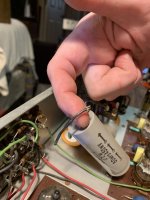
6SN7GTB Zalytron/GE marbled brown base with matched sections $35
CV2492 Mullard military 6922 white label with matched sections $70

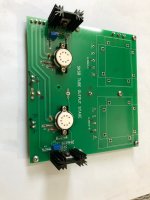
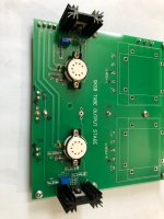
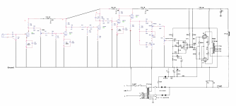
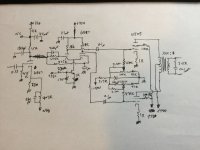
If you aren't familiar with the Impasse, it's a stereo valve pre-amplifier with some interesting approaches from SY's fertile mind. It accepts balanced input, uses input transformers, and can provide either single ended or balanced output. It was designed as a pre-amplifier using an off board potentiometer for volume control, but I built it as a fixed gain stage (a simple jumper) as input for a Pass F4.


More information at the links below.


https://audioxpress.com/article/The-ImPasse-Preamplifier


https://www.diyaudio.com/community/threads/impasse-preamplifier.136835/


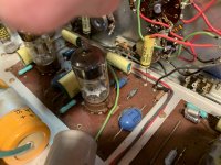
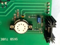
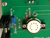
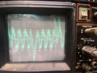
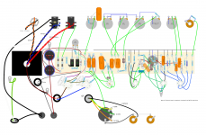
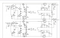
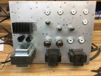
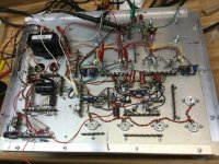
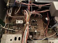
My Impasse is fully working with constant current supply tuned in and neon plus LEDs glowing nicely for Christmas. I am also including the fully stuffed, working power supply board per SY's circuit, both boards designed by jackinnj.

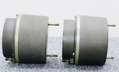
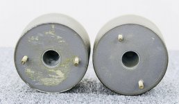
The main board is designed with a separate input transformer section that can be removed and off-board transformers used. At the moment, the transformer section is still attached and uses Cinemag CMLI-15/15PCA input transformers.

The choice of an input transformer seems to be an emotional experience for some. I have another project in mind for the Cinemags, so I will sell board with the input transformer section removed for $60 or with the Cinemags in place for $210. Those little suckers are expensive, but $60 is a great deal if you happen to have a pair of your favorite input transformers sitting around.

I also have a Hammond 290CX mains transformer that I used with the Impasse that I will sell for $50. Of course, that lump will add to the shipping cost.

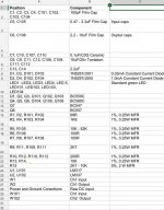
You may have noticed some funny looking, copper colored things sticking up from the main board. At the time I built this project, I was playing around with series/parallel SMD resistors as power resistors. These are homemade circuit boards/heatsinks for the series/parallel SMD resistors. I am using Susumu 1W SMD resistors, so the combination of 4 of these in series/parallel makes a rated 4W resistor. They work fine and should be low distortion, but if you don't like them, just replace them with conventional resistors at the power rating listed in the BOM.

Paypal only. You pay shipping, I pay Paypal fees.

Thanks for looking.

Impasse 3-4 view.JPGImpasse power A.JPGImpasse 3-4b view.JPGImpasse Tubes.JPG

Laser Diode Successor of SLD-104U for SONY ESPRIT KSS Series

The follow Sony laser units (optical pick up for ESPRIT series) are no longer available:
KSS-270A, KSS271A, KSS-272A, KSS273A/B and KSS274A. Therefore only the possibility of changing the laserdiode there are.
So far I bought the KSS150A and set the laser diode to the device for restaurating (mostly KSS-272A), but that is no elegant solution
The 780nM laser diodes inside in all mentioned types of optical pick up's are mostly the follow:
SLD104U (no datasheet)
http://www.datasheetcatalog.org/datasheet/sony/a6802787.pdf (SLD104AU, 5mW)
http://www.datasheetcatalog.com/datasheets_pdf/S/L/D/1/SLD104BUL.shtml (SLD104BUL, 10mW)
For replace I need a successor type from currently production, that is compatible to the old types.
Who can call me currently types that match the requirements from the old SONY types?
at botton pdf circuit diagrams of KSS272A
thank you very much for some advices

Attachments

positioning Raal 140D (ribbon) in horizontal position /w toe-in

After many years of causal research, listeneing, reading and haggling hi end drivers, I have finally settle with the tradiitionl tad alnico woofer in approx 6 cubic ft , the question is about the speakers above 500hz.
I know the best is to get a matching horn, but due to my current collections have deiceded to go with one of Jeff Bagby contracted desgin, , which is AE woofer+ scm75 and raal 70xr ribbon.

However I have the raal 140D tweeter and I have intended to toe-in of my speaker is it wise for me to position the raal horizontally to solve the vertical dispersion issue ?, I am going to put the tweeter into a seos like wave guide so the cut of frequency is good at 2khz , after that atc scm75 will do its necessary work till 500hz. Or shold just make a module design and have the tweeter itself toe in, so I wont affect the woofer and mid range peroframnce

PS
1) I couldnt find a proper wave guide to solve the dispersion problem in the net, if someone know please help, thank you.
2) I am thinking to place atc scm75 and the raal tweeter on the same horizontal axis, is that a bad idea ?

can polarized capacitors be used in an active crossover circuit

Hello, I'm planning on making an active crossover for my 3-way sound system.I'm using mh-audio.nl's active low-pass filter calculator.
The image below is what I received.

My question is:
Why are two polarized capacitors shown on this schematic?

According to what I know, these capacitors are supposed to be non-polarized. Is there something wrong with this schematic?
Thank you all.

1673085228134.png

1 kHz passive notch filter

Hi,

I need a simple passive notch filter for 1 Khz..

I found this configuration with a calculator: http://www.learningaboutelectronics.com/Articles/Notch-filter-calculator.php#answer1

I built it as shown and all resistor and capacitor values are within 1 %.

When testing I see that the dip is around 1700 Hz. and not 1000 Hz..

So according to me something is wrong. Is there anyone with a second opinion?

Regards, Gerrit

Attachments

  • notch filter.png
    notch filter.png
    7.7 KB · Views: 722

QUAD 303 output inductor (choke) question ?

Hi
Does anyone know the value of choke L100 in the output stage of the 303.
I am going to replace all the components on the driver boards. Is it possible to make from scratch this particular inductor ? I know DADA do a range 2uH upwards. prefer to wind my own as long as its in spec. The driver board I have is the one with the transistor / 2 diode arrangement for the biasing. Thanks

A little something to pass the time - TV tubes

Since the new home build was delayed due to weather, I‘ve gotten this back out of mothballs. The original version was going to use the 6LR8/LU8 tri-pents for outputs, but I had trouble making a decently balanced LTP phase splitter with the triodes. Even with a CCS it still wanted to shove most of the current to one side or the other. The dual triodes were far easier to balance. Spent the rainy morning and most of the afternoon dialing in the frequency compensation. Turns out that 200 pF across the g1 resistor is pretty critical with a 40 mu phase splitter. The Miller capacitance of the splitter working against that resistor was eating too much phase margin. No more snivets and the square wave just has a bit of overshoot.

This one is going to have balanced ins and tone controls, hence the unused (for now) sockets. Got a bunch more of those 6BQ7’s. Might try 6JW8’s for the Baxandall circuit. Pentode gain stage, triode output follower with a boot strap for the plate load. Might look a lot more like an ‘ideal’ inverting op amp.

Attachments

  • 9F7AFBBE-4CF5-4FC1-9A10-3558B2D915FB.jpeg
    9F7AFBBE-4CF5-4FC1-9A10-3558B2D915FB.jpeg
    87.1 KB · Views: 265
  • 71BD27C2-495E-4536-939E-F99D0B924B39.jpeg
    71BD27C2-495E-4536-939E-F99D0B924B39.jpeg
    65.1 KB · Views: 265
  • E44E32EB-CE56-4552-8800-5688662DF166.jpeg
    E44E32EB-CE56-4552-8800-5688662DF166.jpeg
    112.2 KB · Views: 252

TSE-II 300B Checkout Help

Just doing my initial checkout after my power transformer arrived from Hammond yesterday. It's a 372HX - 600v CT. I have the primary hooked to the 120v taps (blue/brown). My wall voltage is about 121VAC.

Voltages with no tubes installed:

5842 filaments: 8.84VDC
300B filaments: 4.96VDC
5AR4 filament: 5.48VAC
B- @ R6: 266VDC
B+: -0.36VDC

First, the 5842 filaments look to be quite a bit too high? I realize the voltage will drop once there's a load on it, but I wouldn't expect it to drop 2.6v?

Second, when I install the 5AR4 it starts to arc internally after it heats up. Could this just be a bad tube?

Sony STR V15 Might have blown fuse please help

I bumped into my speaker and then the Reciever seemed to have blown a fuse and stopped working. Probably shorted the speaker wire with the bump. Does anyone know how to fix this issue? I’m attaching photos of the inside of the Reciever too. If you pinpoint the issue can you tell me where it is or circle if possible and tell me what the problem is. I’m a bit new at this.
FD28A7C3-A0F9-4E7B-92F3-E698CA8F4346.jpeg
87B489EE-B57C-44DB-A8BA-BD3639405872.jpeg
DBBAC5B0-A397-4DDA-ABCD-3779EFEEF922.jpeg
146dc752-a19e-4f36-84fb-57c4718209ad-jpeg.1125447
4BC7F596-940A-4208-9008-8AAB9275BD50.jpeg
A97BBC0A-86FB-4A1C-915B-2C2172C49C92.jpeg
429832B1-F7A2-49AC-AB38-0AD3EBF9F543.jpeg
92E0A67D-08DE-4C78-A8CA-991B99B1D6D4.jpeg

Attachments

  • 146DC752-A19E-4F36-84FB-57C4718209AD.jpeg
    146DC752-A19E-4F36-84FB-57C4718209AD.jpeg
    624 KB · Views: 438

Seas Tweeter Integration

SEAS Prestige 27TDFNC/GW (H1462) 1" Bought on a recommendation again a surplus Item at madisound , I think I am going to need to reduce the output . is this a well known model ? Solutions ?​

As a observation I noticed that typical tweeter outputs are often a fair bit more sensitive that the woofers commonly available, is this by virtue of the nature of the drivers? seems like a better match would be tweeters with a lower output to pair with the lower output that naturally occurs from base canceling?​

Projects by fanatics, for fanatics
Get answers and advice for everyone wanting to learn the art of audio.
Join the Community
507,551
Members
7,876,518
Messages

Filter

Forum Statistics

Threads
405,702
Messages
7,876,518
Members
507,551
Latest member
mbwiest