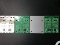
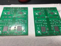
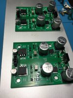
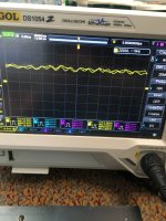
For Sale Aluminum PCBs and stencil for Salas SSLV1.3 fully smd

Hello,

I have for sale 3 aluminum pcbs for Salas SSLV1.3 shunt regulator. To assemble these easier I offer also the stencil.
Each pcb hosts a positive and a negative regulator.

I designed the pcbs because I use them in an application where high dissipation is needed and the project uses an aluminum enclosure to host everything.
I attached the pcbs directly to the side panels which are very effective heatsinks.
No electrical isolation is needed.
I will provide the bom and schematic to be used to assemble the pcbs.

Sold

Attachments

  • 0FB67E69-13E0-442C-B5EF-D21AB258E453.jpeg
    0FB67E69-13E0-442C-B5EF-D21AB258E453.jpeg
    604.4 KB · Views: 361
  • D3953165-5A36-4E59-B97F-2130E34B427A.jpeg
    D3953165-5A36-4E59-B97F-2130E34B427A.jpeg
    461.3 KB · Views: 366
  • C93F69BF-18AD-472B-BC73-2DA430E5B9B2.jpeg
    C93F69BF-18AD-472B-BC73-2DA430E5B9B2.jpeg
    407.1 KB · Views: 369
  • 41984265-6DB1-4062-A8D6-1C621189A123.jpeg
    41984265-6DB1-4062-A8D6-1C621189A123.jpeg
    272.8 KB · Views: 353
  • 310C640E-251D-43C7-A10D-CA3A5637BDC2.jpeg
    310C640E-251D-43C7-A10D-CA3A5637BDC2.jpeg
    475.8 KB · Views: 333
  • BCC58654-8CEF-4305-A469-0E8ED1CEB001.jpeg
    BCC58654-8CEF-4305-A469-0E8ED1CEB001.jpeg
    429.6 KB · Views: 283
  • 573AEC9C-CB56-44E8-9417-0696AC020AB0.jpeg
    573AEC9C-CB56-44E8-9417-0696AC020AB0.jpeg
    463.5 KB · Views: 329

For Sale Pioneer SX-1980

This beautiful unit works perfectly without any issues.
* Still in Excellent Condition, very shiny details ( can see by the picture attached or pm for more )

The Vintage Pioneer SX-1980 is an AM/FM stereo receiver with a unique quartz-lock on station frequency which is immune to time and temperature drift.

It features 2 tape inputs/outputs for tape duplication, exclusive Pioneer twin tone controls with tone defeat switch and many more outstanding features.

Asking prize: $5800

Attachments

  • IMG_20220410_125314[1].jpg
    IMG_20220410_125314[1].jpg
    415 KB · Views: 1,279
  • IMG_20220410_125311[1].jpg
    IMG_20220410_125311[1].jpg
    432.1 KB · Views: 768
  • IMG_20220410_125143[1].jpg
    IMG_20220410_125143[1].jpg
    344.4 KB · Views: 413

How to limit inrush current

Hello, complete new guy here. No training, except what I've recently gotten from YouTube U.

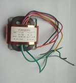
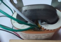
I'm trying to figure out the best way to limit inrush current when I plug in an amp I'm building. The amp itself works fine, but I get a bit of a spark when I plug it into a wall outlet, and do not want to damage any components. This is the transformer I'm using:

Transformer.jpg


My question is, does an inrush limiting circuit go between the wall outlet and the transformer? Or between the transformer and the other components? Or both?

The 40vDC powers two power amps. The transformer also has ±15vDC which I will use to power a preamp. Kind of hard to see, but here is the ±15v output from the transformer:

15v± output.jpg


The preamp requires ±12v, so I'm building a dual voltage regulator using an LM7812. I have just learned that an LM7912 is used for negative voltage, and was wondering, since I've got -15v coming from the transformer, would I still need an LM7912? Does the LM7912 input +15v and output -12v? Or, since I have -15v coming into my voltage regulator, would an LM7812 keep the polarity the same?

Many thanks!

H/K PM-665-VXi: signal-path improvements

Hello Gents,

I recently picked up an oldie which I'm planning ot refurbish as much as I can. I've done a PM-645-VXi a year ago which is now my daily driver. Did the basics like recapping, switch cleaning, trimpot replacement, resoldering etc...
With 665 I'd like go a step further and improve the signal-path if possible. Either with using much better components or even adding or changing the scheme a bit. I'm gonna need a bit a help to push me into the right direction.
I've added the predriver / powerstage part of the scheme to this thread and I do know more or less the actual signal-path but thats basically it🙂

Thx in advance for any advise here...

Willem
WhatsApp Image 2023-01-22 at 12.12.45.jpeg

WhatsApp Image 2023-01-22 at 13.12.06.jpeg

Capture-driver.PNG
  • Like
Reactions: roger2

Switching to RF cables for compactness, or bad idea?

I'm working on multiple builds, amp, pre, etc., and I am trying to make the circuits as compact as possible. One problem I'm running into is once the device is sufficiently small the connectors tend to dominate the footprint; this makes large RCA, XLR and Speakon headers appear very clunky. SMA connectors and cables (even better MMCX) are very attractive just based on the much more appropriate size scale. So, is there some tradeoff in using compact RF connections for audio interconnects?

RF-rca.PNG

Static discharge reboots microprocessor - any way to mitigate?

I've been working on a custom 5.1 LM3886 based amplifier that has Dolby/DTS decoding. I got the Dolby Decoding working the other day, and am working on cleaning everything up and improving all the wiring and what not. One problem that I now have is that occasionally when I touch the amplifier, I discharge static on it. Sometimes nothing happens other than a little jolt, but sometimes the static discharge travels along the volume knob I guess, which is using a rotary encoder and connected to the microprocessor board. The discharge is enough of a jolt that it reboots the microprocessor.

The chassis is anodized aluminum, but it's connected to earth in the places where I've exposed metal. But the outside surfaces are non conductive. All the through components are isolated though, so they shouldn't be grounded, at least not via the chassis. The encoder is grounded via it's connection to the microprocessor board.

My question is, is there any way to mitigate that? The static discharge isn't unique to the amplifier - it's cold and dry here and the same thing happens when I touch a door or other items sometimes. I can run the power and ground to the main digital PSU, but the encoder will still be connected via the two signal lines to the board. My only other thought it is to maybe tie a capacitor between the chassis and volume knob ground, similar to the RCA jacks.

Anyone else have any ideas?

Here's the amplifier and the volume knob for reference:
https://www.dropbox.com/s/jk9wcpsrtym4l3a/IMG_3251.mp4?dl=0

Jigsaw Puzzles

Anyone else here regularly doing jigsaw puzzles?

They say it helps your mind, particularly as you get older. But regardless, I just enjoy doing them. It’s a nice mental challenge and a great way to spend your leisure time. My wife and I do them frequently. In fact, I just ordered five new ones to add to our collection.

I’ve been looking for an Internet forum to discuss jigsaw puzzles, but so far have not found one. So I thought that with all the smart people here there might be enough interest to have a jigsaw puzzle discussion in The Lounge.

Let me know if you are interested. I have some ideas on how to get it started.

ESL63 repair question

I recently acquired a set of ESL63's.... pretty nice cosmetic condition, but lots of popping and hissing, mainly from the top panel. I did some online research and read the service manual. I have determined that the main problem is the stators have separated from the frame in quite a few spots. I found a youtube video with one suggestion for repair, but thought I should reach out to this group for advice on the best way to do the repair. I have removed the metal grill and the dustcover, but the panels are still assembled. I saw a DIY forum post that suggested a polyurethane glue. Any advice would be appreciated. These are serial number 29xxx. I have only looked at one speaker, but both speakers have the same noisy symptoms.

Single Port vs 2 Ports; Affect of Port Area on Low Level Output?

I don't know if this is real or an urban legend. I am seeing a lot of chatter about how low frequency response of a ported enclosure drops off at low volumes, with people saying the larger the port is, the more low frequency response you lose at low levels.

Is there any truth to this? I see this discussion in car audio forums mainly, and I'm not sure what is going on and whether or not it happens with a properly designed subwoofer in a home environment.

I am assuming a comparison between two subwoofer cabinets that have been modeled and design correctly, with the port length increasing as the port area increases, and the box volume increasing to compensate for the volume the larger port displaces.

So if we are comparing correctly designed subs with the same tuning and the same driver, can we generalize anything about the effect of port area on low frequency output at low listening levels? Ports with more area will produce less noise at high volumes, but do they hurt performance at lower levels?

The specifics of my design is 100L/ 3.5ft^3 box, tuned to 21hz, with either a single 3.875" port, or two 3.875"ports. Driver is RSS265HF-4 10" sub. The max port velocity with the single port is simulated to be 32m/s, so using 2 ports would cut that in half. But is there a down side to doubling the port area, aside from the fact that port length increases and the entire box in turn needs to be bigger?

Any thoughts?
  • Like
Reactions: Vic1184

BB OPA604AU SOIC8 Pin 1?

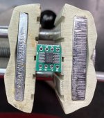
Hello folks. First time for me working with SOIC. I looked at the datasheet which shows a shaded area for pin1, but am unsure how to determine PIN 1 for the parts I have. Your assistance is appreciated.
See attached image of BB OPA604AU SOIC8

edit - My attached pic is of one part laying on a conversion board, not soldered and not sure if oriented ok.

Thanks - Steve

Attachments

  • IMG-8931-smaller.jpg
    IMG-8931-smaller.jpg
    331.3 KB · Views: 105

Sansui AU-X410R advice/help appreciated

My son was given this amp in something of a sorry state. I gave it a quick clean inside and out, and removed a bit of snipped off component leg which was floating about, and it worked! The 'Equalizer' and 'Surround Sound' buttons didn't light up when pressed, but that didn't matter as it was only going to be used for playing music from his computer.

It worked for a few weeks, but now switches on but there is no sound. I couldn't hear or feel the speaker protection relay clicking, so I removed and checked it - it clicked when 6v dc was applied, and there was no voltage at the terminals when installed on the board. I replaced a 1uF 100v capacitor and a C2235 transistor next to the relay without effect.

I can't seem to find any information or diagrams for this amp - could anyone advise on what else I could check? I can use a multimeter and a soldering iron and follow (simple) instructions, and recently restored an old transistor amplifier with help from an expert on Vinyl Engine. I know it's not a great amplifier, but it sounded fine, and I'd be interested to learn!

It uses Toshiba A1939 and C5196 transistors, and this is the relay. The capacitor and transistor to the left are the ones I replaced, and you can see the generally grimy state of things....
IMG_3207.JPG

I would be very grateful if someone could point me in the right direction!

Past 2 way build and looking to build the same one but, with better parts and drivers.

Good morning everyone. So I built a 2 way for my dad coming up on 15 or 16 years now? I used a Silver Flute 6 1/2 inch driver at 8 ohms model number # W17RC38-08.Then I used a Sea’s Textile dome tweeter model # 27TDC (H1149). I used mills resistors and Aircap in the tweeters path. I can’t remember how I did the woofers? I think it was with Aircap as well? It’s been along time? I built a rear ported standing box with a top and bottom sealed sand storage chambers. Has helped with vibration and discoloration in the souls plus they are heavy. So now fast forward to today. My wife as asked me to build her a pair identical to the ones I made my dad. I want to do a few things differently and do the basic 2 way but, with a sea’s tweeter and a different woofer? Any thoughts? Thanks Jeff

AMP and DIY speaker Matching. RMS an issue?

Hi all!

I am in the process of finalizing my design of a MTM DIY speaker. I have the cabinet modeled, crossover pretty close to final, but what I am now concerned with is amplification. I know this can be a controversial subject, but I hope I can at least get a better understanding of things.

My crossover should have a final impedance of 4ohms. From my understanding, the woofers usually are the ones who determine the power handling and impedance of the speaker. I am using 2x DA RS150 8ohm woofers in parallel, and a DA RS28 4 ohm Tweeter. The combined RMS handling of the woofers should be 80watts (40 watts each), and the tweeter is 80 watts at 4ohms on its own. I am looking to use the Anthem MRX740 AVR and then the Emotiva BasX A3 3 channel amp for the three MTM speakers I am trying to build. I am looking to make these speakers into a LCR set up for music and home theatre. The BasX amp can push 200watts RMS into 4ohm with all channels driven (or 140watts into 8ohms).

I am afraid this might be over kill for these speakers though... I have heard that it can be beneficial to run speakers 1.5x above their RMS for dynamics as long as you are not listening to it too loud as to use all its power for too long which may fry the voice coil or cause mechanical damage. I generally don't like to listen to anything much above 90-105db for very long, and music usually is comfortable for me at around 90-95db. Would this be a good, or bad pairing?

Any thoughts or suggestions? TIA

Refurbishing Marantz Imperial 6 Speakers

Hi there, I am new here and I am looking to get a bit into the DIY audio scene.

To start off I want to refurbish a set of Marantz Imperial 6Gs. I am looking to preserve their inherent qualities, as opposed to trying to make them into a set of speakers they aren't. These won't be the only speakers I tend to own. Right now from what my untrained ears have to tell me, they sound just fine. I have little experience with electronics but I have no problem doing research to learn. What I find difficult is determining what quality speakers to replace the stock ones with, and how important a less or more expensive capacitor and inductors will be.

One of the woofers dome is punctured and both tweeters are dented. I am assuming this can't be repaired and that I'll need to buy a new speakers?

I have uploaded pictures of the speakers as well as schematics.


Here is the list of supplies I'll need to refurbish the speakers. I read here..
http://www.diyaudio.com/forums/multi-way/78350-recapped-imperial-7s-tonight.html

that it would be a good idea to increase the power dissipation in the resistors. So I choose 10w resistors. Though I couldn't find some resistors (at Parts Express) with a 10w buffer. So I listed options for those slots.


If I go to a site like Madi Sound Speaker Store, I can find all of the appropriate resistors and capacitors. Will the Dayton Audio PMPC-6.8 6.8uF be a fine choice for these speakers, or is there any added benifit to geting a more expensive capacitor such as Mundorf 6.8 mfd Supreme Caps. Since I am just starting out, I don't need to jump to extreme Hi-Fi. Probably worth the journey to the top.

All of these parts adds up to ~$230.

Any suggestions for different paths to take? Any guidance would be greatly appreciated.

Cheers,
Daniel

R1
4 ohm 10w resistor

R2
3 ohm 10w resistor
3 ohm 10w resistor

R3
1 ohm 10w resistor

R4
6.2 ohm 5w resistor

R5
8 ohm 5w resistor
OR
8 ohm 20w resistor
OR
8.2 ohm 10w resistor


C1
Dayton Audio PMPC-6.8 6.8uF 250V Precision Audio Capacitor

L1 - 15awg vs 20awg?
Jantzen Audio 1.0mH 15 AWG Air Core Inductor Crossover Coil

L2 - 15awg vs 20awg?
Jantzen Audio 0.60mH 15 AWG Air Core Inductor Crossover Coil

Speaker Replacements

Tweeter Replacement

Woofer Replacement

Future Amplifier Options

I have been considering building the AMP CAMP AMP KIT. Will that kit be able to drive these speakers? Right now these are being used in a small room, and will probably stay there for the foreseeable future. I don't plan on maxing out the volume of the speakers.

Attachments

Splitting the outputs on an R-core transformer.

I have this R-core transformer, which has two 110v inputs but has not separate outputs, which I would like to have.

From what I see from the outside it might be very difficult to reach the output wires and re-assemble it properly. Am I right?

Has anyone did anything like that and guide me through it?

Attachments

  • R-core #1.jpg
    R-core #1.jpg
    369.2 KB · Views: 332
  • R-core #2.jpg
    R-core #2.jpg
    247.3 KB · Views: 367

Marantz model 16 possible mods?

Ok all you Marantz people (and others)
I've got a Marantz 16, a dual mono power amp soon to be on the bench for an overhaul/restoration - the 100w-100w version.
I'm concerned about the input section, it wasn't built with any type of balancing attenuator.
So if both of the monoblocks are a tad bit "off balance" from each other, a preamp balance adjustment must be done.
I want to add in a multi-turn trimmer on each amp so both amps are in perfect Db balance to avoid preamp adjusting.
I've come up with this (in schematic) - does anyone have an issue with this? - I want to have around a -3Db adjustment range that should be sufficient, eh?
Marantz 16 Mod.jpg

Mid Range Line Array optimization and build

I need a very high quality and loud mid range for my system. Big and powerful single drivers usually don's sound usually very detailed or natural and they beam of course at higher frequencies. The smaller ones sound unnatural at lower frequencies and the sound becomes easily distorted and the driver easily might overheat at higher power levels.

I initially thought about putting four mid range drivers in a circle, but that still would have the beaming problem and I was not sure if even four small drivers would have the amazing dynamics I am looking for.

So that basically left me just one option, a line array. I now built one speaker quickly, just to test it. I used eight 6" SB17nac35-8 ohm drivers because of their really good sound quality and they are now taking care of 200 - 3000 hz area quite well.

sb17nac35_midrange_line_array_proto.jpg


The speaker is 2.0 meters (6.5ft) high and those eight drivers produce a sweet spot vertical listening window of about 90cm (3ft) high according to my listening. Horizontally, it's very nice and wide as you can probably guess since I am using 6" drivers.

I am very pleased with the result, this was the right choice for me and now I just want to build the final version. However I am not sure how many drivers is the optimum.. I could just do a bunch of test speakers, but I would rather skip that if you can guide me.

Based on my listening I need at least two more, so that would be 10. And since I am running the speaker to 3 khz I will also cut a slice of each driver from top and bottom to bring them closer to each other for more uniform sound field and for a little bit more higher power density. After cutting, the height would be 150mm instead of the 171mm that it's from the factory.

The maximum amount would be 16 drivers, since I don't wan't to make the speaker any higher than that. Naturally I would go for that amount, since the longer array is beneficial for the directivity, but I am worried how lowest and the highest drivers are more far away from the listener than the ones in the middle. Could that become a problem? Right now, with eight drivers it's not an issue to me, I hear the details very clearly. I could also assign two more channels in the crossover and the amplifier to delay the eight center drivers to compensate a bit.

Which amount would you choose and why?

Pioneer PL-S30 TT measurement for a Franken-repair

Does anyone have a Pioneer PL-S30 turn table who could measure the distance from the center of the plate to the center of the tone arm pivot shaft for me? I have modified Phillips 777 TT which I have had trouble with the tone arm hanging up (very bad for records). I removed the auto start/stop mechanism, which fixed the problem for a year or so but now it's back; the OEM pivot bearing assembly is mostly plastic which is starting to disintegrate. I have a Pioneer PL-S30 tone arm assembly that I am going to replace the 777 arm with. Does anyone have a Pioneer PL-S30 that could measure the distance from the center of the plate to the center of the tone arm pivot shaft? Note that this turn table is special to me because I removed the lower half of the plastic body and made a custom wooden two-tone plith that upgrades it to a furniture accessory that my wife lets me keep in the living room. Plus it matches my 1966 HK TA5000x mahogany case.

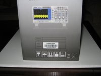
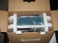
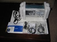
For Sale Hantek Digital Storage Oscilloscope / Model DSO5202P

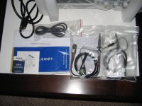
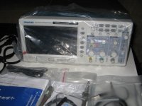
For Sale: Hantek Digital Storage Oscilloscope / Model DSO5202P

I purchased this a couple of years ago. I think I used it 3 times and (at the time) due to my working life where I traveled a lot, back in the box and on the shelf since then. The scope is in as new shape. It includes two probes, electrical and usb cable, and the instruction CD.

I checked Circuit Cellar at $368.00, Aliexpress at $333.00, Amazon at $319.00, and Banggood at $339.00.

Asking $275.00 shipped. I will cover the shipping and paypal fees. Paypal only. No returns. Thanks.

Attachments

  • IMG_1612.JPG
    IMG_1612.JPG
    524.2 KB · Views: 156
  • IMG_1613.JPG
    IMG_1613.JPG
    606.5 KB · Views: 138
  • IMG_1614.JPG
    IMG_1614.JPG
    610.2 KB · Views: 140
  • IMG_1615.JPG
    IMG_1615.JPG
    624.9 KB · Views: 146
  • IMG_1616.JPG
    IMG_1616.JPG
    600 KB · Views: 160

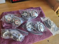
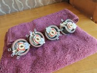
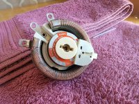
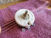
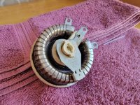
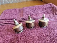
Ohmite Model K & H RKS25R 0448 25 Ohm 2 Amp 100 Watt Rheostat - 50 ohms 25 Watt Model H 50 and others

Anyone need these?

Attachments

  • 20220802_161145.jpg
    20220802_161145.jpg
    644.7 KB · Views: 130
  • 20220802_161531.jpg
    20220802_161531.jpg
    873.4 KB · Views: 174
  • 20220802_161541.jpg
    20220802_161541.jpg
    819.7 KB · Views: 133
  • 20220802_161545.jpg
    20220802_161545.jpg
    835 KB · Views: 120
  • 20220802_161556.jpg
    20220802_161556.jpg
    844.5 KB · Views: 117
  • 20220802_161623.jpg
    20220802_161623.jpg
    832.9 KB · Views: 125
  • 20220802_161649.jpg
    20220802_161649.jpg
    725.3 KB · Views: 116
  • 20220802_161653.jpg
    20220802_161653.jpg
    731.4 KB · Views: 115
  • 20220802_161750.jpg
    20220802_161750.jpg
    696.9 KB · Views: 110
  • 20220802_161906.jpg
    20220802_161906.jpg
    849.3 KB · Views: 112
  • 20220802_161910.jpg
    20220802_161910.jpg
    882 KB · Views: 133
  • 20220802_161917.jpg
    20220802_161917.jpg
    829.7 KB · Views: 118

Project Polk T50

I got a pair of Polk T50 at the flee market for a song. I thought these might be interesting to improve. The have some blown tweeters and the single 6.5 driver is stiff in both and one has coil rub. I knew this when I got them and bought them for the enclosure. In my system I run the Yamaha NS10M for front mains. And while these sound awesome (more so the closer you get) i wanted more power capability and to be able to better keep up with my Sub Woofer setup (2 custom ported 15s driven with the Kenwood L09M>
I don't mind some wood work but I am trying to make this a project others could also do if my results turn out good. The cabinet is nice but these are quickly overpowered. After lots of poking around on Parts Express I settled on the Morel CAT 378 with 2 each tower Dayton .
Im not set in stone and still exploring how to best load and use these.
It also would not be much work to separate the tower with a panel in between the upper 2 6.5 locations. I could use on or both passive radiators by adding a hole in front or to one of the lower side panels. I could also go 3 way with a TMWPsvRad
What thought have you all on how to load these. I'm not trying to go crazy on money and want to go the best path as far as speaker placement topology. 3 way costs a lots more. I have no idea of the effect adding a second woofer in parallel would have with more power and just one passive radiator.

Attachments

  • IuzItRxC.jpeg
    IuzItRxC.jpeg
    691.5 KB · Views: 398

Denon PMA250II question

Hi all, I recently purchased a Denon PMA250II amplifier. I think this little amp is rated at 30 watts per channel into 8 ohms and dates back to late 1980s. Some of the pots and switches were a bit scratchy but responded well to cleaning with a known commercial cleaner. At least for the most part! The input selector switch is still a bit dodgy on CD setting but fine on tuner and aux. If you switch to CD input, sometimes one of the channels has low output. I have cleaned the switch a couple of times and while it is much better, it is still not prefect. The input selector is a strange beast (see images). The switch has what appears to be a ribbon cable with blue plastic ladder type support framework attached on one side. This may be removable as it appears to be clipped in place. This terminates at a docking block near the rear of the PCB. If I push on the top of the docking block while in CD mode, the signal to speakers drops in and out indicating a poor connection at this end. This does not happen when in Aux or tuner mode. The thing is, I'm not sure that the connecting cable is actually a ribbon cable or some sort of resistor. I say this because the actual switch has a plastic shaft with several protruding knobs that articulate with the connecting cable at various points which may indicate that this has something to do with input selection. I have not seen a switch like this before. Does anyone know how this system actually works? I'd like to fix the issue if I can. Any thought or suggestions much appreciated.
20221027_141917.jpg
20221027_141924.jpg
Glenn

ELROG tubes, anyone know much about them?

I just discovered this company last year.
They seem to only make high end tubes such as 300B, but it appears the company actually is from the remains of Telefunken which brings into question if they still possess the original Telefunken tooling from their factory.
Would be great if they have all the company secrets from Telefunken, Im assuming someone out there still holds all this data?
Would be interested to know more, but at least there are other companies outside China and Russia who can make tubes.
If they are able to produce 12AX7 and other tubes like 6L6, EL34, etc, that would be awesome.
If they own the telefunken tooling, it may be possible to get reproduction Telefunken tubes, but the biggest secret with Telefunken tubes was the alloy formula for the cathode materials, this was a trade secret of Telefunken and not patented.

8" subwoofer recommendation please

Hi Thanks for reading. Can i please have a recommendation for a good quality 8" subwoofer.

I purchased an BK electronics bpv500 plate amp, unfortunatly it has a high current output, which is good for bass, but my cheap wharfedale driver could not handle that much current and is distorting all over the place.

So i need an 8" driver, specalised for bass only response, power handling of 200 watts, crossover frequency is 100hz, enclosure volume is 1.8 cubic feet. A driver that is rugged and can take a beating. Budget is £125. Preferably 8 ohms.


Many thanks

Help putting spares to use?!

Hey all,
I’m not much of a speaker builder-I like rebuilding vintage Scott and Macintosh amps. However, I have 2 very good 25F-EW woofer/drivers and H087 tweeters from trashed Dynaco A25’s cabinets and four Vifa 5.5" P13WH-00-08 (NOS) from the 2010’s. Any chance a 3 way speaker could be built that might sound good with a combination of these three drivers? I have building skills and tools but crossovers/frequencies and speaker culture in general are not my thing. Any ideas or should I just sell this stuff off?

Omni-directional-ish Speakers?

Hi, are there any speaker designs that project sound 360 degrees around, in phase, but more forward than to the sides and back?

Closest thing I can find are the Fulcrum Audio subcardioid speakers: Passive Cardioid Technology™ | Fulcrum Acoustic

But they're PA speakers :/

There have been so many loudspeaker designs over the years...I don't know where to start looking!

Adriel's Introduction - Coming Somewhere From the Sonoran Desert

I jumped right in and didn't introduce myself, turns out there is an introductory sub forum. So here is my attempt, I might be a little long so maybe grab a tea, cocoa, or a pop.

Let me start with that I am Autistic. This affects my perception and preference of music and equipment. For example, after listening to an Audio Technica cartridge for a while, my ears hurt from the high pitched noise. Another, I enjoy feeling music, one reason I love classical organ music; this does not mean having my eardrums beaten to a pulp. Additionally, I can hear past the normal range of hearing, been professionally tested and for fun tested myself in physics with a sound generator (asked my fellow students to let me know when they could no longer hear the sound, then I went until I could no longer hear).

Let me say, music saved my life. How, you ask? Well, I was severely abused by biological "mother", so bad in fact contemplated suicide when about nine or ten (memory is hazy), until found her LPs and some reason started playing them (neither of my folks played them after I was born), the ideas got me thinking differently and kept me going, until just after turning 12 rescued by Dad and his folks (Oma and Opa).

In my mid teens I started finding LPs at library sales, then life got busy and stopped collecting. Fast forward sometime during studying at university, no family around, and got back to enjoying them, until my all in one was stolen. Time went by, got the itch, then to keep it short, spent years trying to get a useable sound system, not knowing anything. The worse decision was purchasing a U-Turn turntable, absolute rubbish, belt too big, solved by applying weather sealing foam tape to enlarge the platter, didn't have the time or energy to do it right. Then this spring, family stole the house I was living in (for the better, it was an abusive situation, plus this new place is far superior) and there is no room for the horizontal Telefunken console, so based on a friend's suggestion, looked into Technics for the equipment and he gave me vintage Grundig vintage speakers some **** hacked the legs off of (sadly listening to a home recording of an interview of a long ago deceased relative had a right channel spike and now sounds awful).Doing a plethora of research and eBay hunting, built a system consisting of: a SU-Z600 amplifier, M234X cassette deck (love the DBX noise suppression), and a ST-S707 receiver (stellar FM reception, have not gotten an AM antenna, though bet be also just as amazing). I eventually will add a turntable and compact disk player, in that order.

I had too many hobbies, trimmed down to just a few, so collecting equipment isn't going to be one of them. However, I am here to explore and learn, as a "bipartisan", with the intent to over time, knowledge and funds permitting, try upgrades (though my funds now have to go to rebuilding a Volkswagen 1200cc engine).

If anyone inclined to know what my other hobbies are:
Art, in the mediums of acrylic, charcoal, photography (Olympus OM SLRs or my great Aunt's 620 format Kodak), and watercolor.
Air cooled Volkswagens (I much prefer the Type 3 though inherited Dad's 1964 Beetle he bought in 1968) and doing all the work myself (except rebuilding transmissions or steering boxes and paint (though do body work including welding)).
Music, listening to and playing. My first instrument was clarinet, mostly Oma's choice, then harmonica (fifth grade teacher taught all his students, keep trying to get back to it), piano (I still have the one I learned on), taught myself organ (Hammond M3 which also still have, though sadly in a hot storage unit), and cello (borrowed from the school). I enjoy traditional bluegrass, classical music, folk, hymns, classic jazz, 1970s and 1980s discotechnick, rock and roll from about the late 1950s through about the late 1970s, some 1980s glam rock and pop (ex. Cyndi Lauper), and various rock pieces afterwards (if can't understand the words or is too 1990s onward, don't find enjoyment).
Tailoring, self taught and still learning.
Upholstery, just started learning last year.
Used to have twice as many, though took my friend's advice and no longer involved.

Oh, and if any of you are wondering, I was born during the Regan administration, do the math.
:p
😛

There are great sounding and not super expensive 2-way designs. Why go for 3-way, then?

Hi! I'm a noob in speaker design, but I'm trying to learn. For a while I used to think 3-way is better than 2-way, because duh, of course a specialty driver is better. Then I started noticing that prominent speaker builders create both 2-way and 3-way designs in seemingly equal numbers, and there does not seem to be a strong preference either way, even when cost is no object.
In my eyes, 3-way designs have some objective drawbacks:
1. More drivers = larger baffle area required, more difficult construction, higher cost and build effort.
2. More complex crossovers = harder to design right, higher cost.
3. Possible issues with the sound field summing up properly, more distance required from the speaker to the listener? I just made this up, please tell me if it can be an issue or not.

What are the benefits, then?
A use case that I'm most interested in: if we state that the speaker must only go down to 80 Hz, or even 100 Hz, what are the tradeoffs and considerations in the 2-way vs. 3-way debate? And no concert-level output required, let's say normal listening level is 90 dB at most, short peaks notwithstanding.

Obviously, a 3-way is great for getting deep base, but in my experience a free-standing dedicated subwoofer is better than one integrated into the speakers.
  • Like
Reactions: Grarea

Excessive Heater Elevation Voltage?

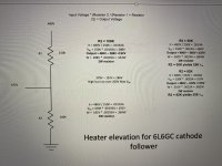
All the parts have come in for the refurbishment of my ShoBud Compactra, including a 6.3 VAC transformer for the 6L6GC cathode follower. The tube has 378 VDC on the cathode - way over the max heater to cathode voltage. Some say just leave the Vhk voltage alone as it has worked fine (as far as I know) for decades. The elevation voltage level would have to be quite high just to get the Vhk barely in spec. 90 VDC is about the highest elevation voltage I have ever heard of. Would almost 200 VDC be too high? My voltage divider math is attached. Thanks

Attachments

  • IMG_3230.jpeg
    IMG_3230.jpeg
    678.7 KB · Views: 126

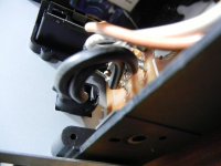
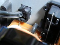
Need help with Sony ES disassembly

No access to the bottom of this unit, unlike many other Sony receivers, and I need to take out the main board to get to solder side connections.
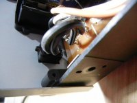
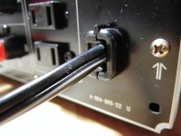
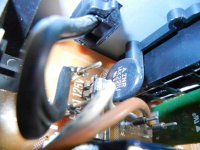
The only thing I can't figure out is the power cord situation. The leads appear to be both wire wrapped and soldered.

I was hoping to undo the strain relief and feed enough cord through to allow me to remove the board from the chassis.
Any idea how to remove it (since I have access from the inside)?

All suggestions - regarding any approach - are welcome.

EDIT: Upon closer examination, the two leads of the power cord do not appear to be wire wrapped. Instead they appear soldered to posts with two distinct upright protrusions (?) [see last three photos]
Anyone familiar with these?

Attachments

  • DSCN9180.JPG
    DSCN9180.JPG
    570.7 KB · Views: 91
  • DSCN9181.JPG
    DSCN9181.JPG
    528.2 KB · Views: 86
  • DSCN9186.JPG
    DSCN9186.JPG
    545.4 KB · Views: 91
  • DSCN9189.JPG
    DSCN9189.JPG
    572.8 KB · Views: 89
  • DSCN9195.JPG
    DSCN9195.JPG
    606.4 KB · Views: 55
  • DSCN9197.JPG
    DSCN9197.JPG
    567.1 KB · Views: 64
  • DSCN9198.JPG
    DSCN9198.JPG
    526.1 KB · Views: 56

Idea for grille cloth

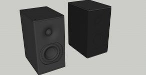
mini monitor II.jpg

Was messing around in Sketchup with a mini speaker, 4in mid and 1 1/8 tweet, and had recessed the tweet in a shalow waveguide. Then i thought about the possibility of grille cloth. Only for aesthetics.

Pantyhose?

I'd need to recess the mid just enough that the rubber half roll cleared the baffle face. The top and bottom are just caps that are screwed on to the body of the speaker. The grille cloth is one leg/thigh of a pair of 5X pantyhose. Cut the hose into a pair of tubes and slide over the speaker. Light coat of spray adhesive on top and bottom holds the ends in place. Replace the panels to finish it off.

If fabric is ever damaged, or you just want a different 'look', it's cheaply and easily replaced. Hosiery is available in a range of colors, patterns, and opacity, and probably 99.9 pecent acoustically transparent.

Attachments

  • mini monitor.jpg
    mini monitor.jpg
    107.2 KB · Views: 88

For Sale Dynaco PAT4 Preamp

Sold

This is a project unit, I see several things that need to be corrected:
1) The main filter cap is bad, the unit has a hum, and the voltages are way low.
2) The Stereo/Mono switches have been disconnected, see closeup picture.
3) The set screw for the Volume knob is frozen

It looks like several caps on the boards and front panel have been replaced at some point.

Cosmetically there is some lettering missing on the front panel (Selector Switch "Spare", Loudness Switch "Off") and there is a bit of corrosion on the tone control knobs.

Aside from powering it up, no other testing/checking was done.

Includes the manual with the foldouts & some additional sheets.

$75 plus shipping, Con US only.

Img_0988a.jpg

Img_0989a.jpg

Img_0990a.jpg

Img_0986a.jpg

Img_0987a.jpg

Simple Project for a laser cutter

Hi everyone guys, first of all thanks for this great forum!
I just received a new laser cutter/engraver, and i was planning to create, as my first project, a subwoofer for my audioengine a2+ a small 2.0 desktop kit.
I'm a complete noob in Audio DiY so i'm looking for something simple to cut, and with all the explanation needed on the parts to buy. I'm not confident to build the crossover by my self, so just planning to buy a kit for the elecronic parts.

Do you have some suggestions on where to find the project (with the cad files ) and the parts to buy?

checking interest: LADSPA plugin for generating euphonic or other distortion

I have written several LADSPA plugins to date. For the uninitiated, these are pieces of software that process audio under an audio "host" on computer hardware running a Linux OS. I use LADSPA plugins to implement DSP crossovers, and various other tasks.

Within certain DIY audio circles there seems to be an interest in adding a couple of percent of ear/brain-pleasing "euphonic" distortion, specifically 2nd order, to the playback chain. You know who you are. It's not really something I seek in my own equipment, but it might be fun and edumacational to experiment with the addition of distortion in a controlled way. Here is (potentially) one way to do that.

The idea is to define a transfer function that will be applied to the audio signal. The TF is just a "curve" that is the input-output voltage relationship. Samples come in, get multiplied by the transfer function, and then are spit out. The "curve" of the transfer function describes how the audio waveform will be altered. By defining the TF with various shapes you can create distortion with predominantly odd or even order harmonics and the extent to which the TF is curved away from the purely linear out=in sets the level of distortion that is added to the signal. The TF would be defined within the plugin as either a table of values to interpolate or an analytical function. The output signal from the plugin can be analyzed to determine the distortion level and harmonic distribution like any other signal. The TF data could then be shared with other users who want to implement it on their own systems. It might be possible to measure the TF of actual physical devices that have nice distortion signatures and them implement them in the plugin to get that "sound" out of your analytical equipment when you want that, and defeat it when you don't.

That's the basic gist of the nascent idea of a plan at least. Interest? Thoughts?

Some related info here:
https://www.ka-electronics.com/images/pdf/ThesoundofDistortion.pdf
http://www.till.com/articles/harmonicdistortion/index.html

Fulcrum Audio's PASSIVE, sub-cardioid subs.

Have you guys seen these yet? I think they've been around for a couple of years now.

David Gunness / Fulcrum Audio have a line PASSIVE cardioid speakers. The size / weight / dB output per watt is sort of amazing, considering how inefficient and large most active cardioid subs are. Gunness is obviously one of the really talented audio guys out there, but still the specs on these subs look WAY better than they should.

Specs below, but I'm wondering if there's any way a DIY guy (Not me, but a really knowledgable engineering type) could design something similar?
In addition, you'd need to figure out the DSP that's going on. Sounds daunting to put it mildly, but this might be a new bar to reach for, at least with BR subs.

Login to view embedded media -----------------------

Check out, for instance, the 2x12" Fulcrum Audio CS212L. (They also have similar subs with larger drivers)

The sensitivity is only 95 dB, with a power limit of 700w per driver at 8 ohms, yet they claim a max continuous SPL, @ half space of 132 dB.
I don't see how that's even possible.

They also claim 8 dB of rear-rejection across the entire usable bandwidth, with (from what I can see) no lobing on the sides. - which is also sorta' hard to believe.

Mind you the retail cost is over $2800 for a single 2x12", and I THINK you need to run them in pairs, plus you need a qualified processor to run his TQ dsp.

This is making me wonder if I should even bother building a new version of my current 2x12" boxes, or even try a small TH.
  • Like
Reactions: sonomanie

Another Crown Macrotech 1200

Greetings,
Trying to get this amp up and running after stupidly inserting one of the output ribbon connectors off by one pin (no locating mechanism on the header). This exploded the amp with energizing - D'OH!! (This was over 10 years ago).
I did this after a cream-puff fix for thermal distortion happening after warmup. The pre-drive transistors Qx17 and Qx19 were visually drifting off their heatsink (chassis, I believe). So, I removed them and re-fixtured the hold-down tabs for positive contact pressure - piece of cake, until plugging in said connector.
I've already replaced about a dozen parts, the +/- 15V bridge diodes bought it the worst, along with their traces. Only one of the HS NPN transistors was damaged (replaced).
Amazingly, the front-end opamps are working, and I can get the output to translate voltage to the speaker terminals, but as soon as a load is connected, the positive rail is truncated; does not seem (sound) to be drawing current. I've been pulling my hair out comparing it to the 'good' channel, but cannot locate a smoking gun (poor choice of analogy).
The worst part is having to work with ballpark schematics. The MA-600/1200 docs are quite a bit off in the Last Voltage Amp stage, as I found another closer to what I have: "MR MAIN". One part I cannot find, and is present on either schematic, are the LM339 comparators, and there are a handful of them, supposedly.
I've been reading other very helpful posts on bias voltages, and such, but still up against a wall.
Any help would be greatly appreciated. I'm a Design Eng Tech with 40yrs exp; 7 were at a music store selling Crown amps.

For Sale Douglas Self Preamp from Linear Audio 5 kit, Tested and ready to play

This preamp is built off of the DIY project described here:

Dself
Linearaudio

Features:
2 XLR and 3 RCA inputs, relay switched
Balanced and SE outputs
Active variable gain. 3x gain for XLR (10dB), 1.5x for SE (4dB)
Max output ~10V (XLR)
HF and LF tone controls (defeatable)
Balance controls
Excellent measurements

Build notes:

Opamps, Ribbon cables, Rotary Switch CK1059 Lorlin not included
Rotary switch PCB included
PR9372 Metal Film Resistors, Caps - Nichicon Muse (ES), Nichicon Fine Gold (FG), Wima MKP, RelCap Film & Foil Polystyrene
Binned the volume pot for best channel matching -- better than 0.2dB across the entire rotation

It ultimately cost me around €350 to build,
My asking price is €250 or best offer, shipping and PayPal fee (EU)


IMG_3789.jpg
IMG_3790.jpg
IMG_3791.jpg
IMG_3792.jpg
IMG_3793.jpg

For Sale LM4780 and 81 Diy 5.0 audio amplifier kit "with power supply pcb and connectors"

LM4780TA and LM4781TA Diy 5.0 audio amplifier kit including power supply PCB,
with Sanken rectifier bridges and connectors 68€ more shipment.
"Without the powersupply the price is 53€ includind amp connectors"
Here populated power shown as an example
Tracked shipment to European union
Skematics sended together with articles
Payment by paypal
1669475282158.jpg
1669475446841.jpg
1669475282143.jpg
1669475600955.jpg
1669475542060.jpg
1669475542073.jpg
1669475542069.jpg
Projects by fanatics, for fanatics
Get answers and advice for everyone wanting to learn the art of audio.
Join the Community
507,586
Members
7,878,410
Messages

Filter

Forum Statistics

Threads
405,784
Messages
7,878,410
Members
507,586
Latest member
kingburry