You are using an out of date browser. It may not display this or other websites correctly.
You should upgrade or use an alternative browser.
You should upgrade or use an alternative browser.
Filters
Show only:
Has anyone ever used miniDSP and Equalize apo at the same time?
I am using only Equalize APO.
If it is set based on a desktop, there is no limit to the number of tabs of the fir filter, so I always avoided purchasing minidsp's dsp.
But I became curious.
Usually, minidsp has a limit on the number of tabs of the fir filter and a limit on the number of IIREQ.
However,
PC --- Minidsp --- Speaker, Sub whatever
Does using additional FIR filters on Equalize APO apply to all when the basic crossover, delay-adjusted 3 channels (assuming 2 speakers, Sub) are played on the computer in Minidsp?
If that happens, I will buy it right away regardless of the tap limit of minidsp.
As a person who enjoys the process of optimizing the phase using the fir filter directly, I don't want to use the Dirac of minidsp, and I enjoy using the 65536 tab on my PC.
If anyone is using Minidsp, I'm looking for someone to test if what I'm worried about is actually possible.
Source of affordable 19” 2u chassis in USA
Greetings!
The title says it all.
Looking for recommendations on standard 19” rack mount chassis. 2u or 3u height.
Can order 3 at a time, but not 50!
Thanks
The title says it all.
Looking for recommendations on standard 19” rack mount chassis. 2u or 3u height.
Can order 3 at a time, but not 50!
Thanks
Pentode (triode connected) in a choke loaded cathode follower...where to connect G3?
- By toshiba_nz
- Tubes / Valves
- 6 Replies
Hello everybody 🙂
I have a pentode (triode connected) in a choke loaded cathode follower configuration ...where do I connect G3 (the suppressor grid)
1. Leave it / NC
2. Tie it to the plate/anode
3. Tie to the cathode
4. Zenner bootstrap it to somewhere (details?)
5. something else
I have a pentode (triode connected) in a choke loaded cathode follower configuration ...where do I connect G3 (the suppressor grid)
1. Leave it / NC
2. Tie it to the plate/anode
3. Tie to the cathode
4. Zenner bootstrap it to somewhere (details?)
5. something else
13.8V Power Supply
- By Grenny
- Power Supplies
- 14 Replies
I am wary of trying to build my own power supply for various chip amp and discrete amplifiers and I was naively wondering if I could use a fixed 13.8 volt linear power supply 10 A, such as:
https://www.velleman.eu/products/view/?id=420118
Would it give enough noise free power for various designs like the LM3886 or ESP 3A. Thank you for any help.
Grenny
https://www.velleman.eu/products/view/?id=420118
Would it give enough noise free power for various designs like the LM3886 or ESP 3A. Thank you for any help.
Grenny
For Sale Hashimoto A-305 interstage trans. pair-new
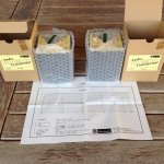
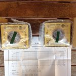
New unused pair of Hashimoto A-305 intertage transformers. In factory boxes with tags yet to be fixed to transformers. Brand new condition.
Transformers are in Australia from where the will be shipped very securely
Price for the pair (excluding shipping) is AUD$1250 (approx US$840)-excludes shipping. If you have a sensible offer, feel free to pm me and maybe we can agree on a figure.
Transformers are in Australia from where the will be shipped very securely
Price for the pair (excluding shipping) is AUD$1250 (approx US$840)-excludes shipping. If you have a sensible offer, feel free to pm me and maybe we can agree on a figure.
Attachments

High power, high sensitivity tweeter at 20Khz
- By guyst
- PA Systems
- 27 Replies
Hi to all,
Im looking for a high power (100W+) tweeter that has high sensitivity at ~20KHz. So far my best find is DS18 PRO TW120 which, according to the website graph, puts out 105db at 20KHz; but its a 60W driver so not very powerful. Other considerations are secondary (sound quality, impedance, size, etc). I simply need maximum SPL at ~20KHz.
Thanks
Nakamichi PA-1 Schematics
- By gto127
- Solid State
- 18 Replies
Does anyone have a link to Nakamichi PA-1 schematics or have one in a pdf file? I'm afraid to pay to download any nak manuals because I've got bitten a couple of times by companies that sent download Nak service manuals on items during that time period without schematics. I was unable to get a refund on both occasions. Thanks for any replies
Tweeter Wiring Positive and Negative?
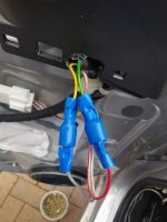
Hi All I've installed Audison AV 1.1 tweeters in my car and it has a striped red wire, is this positive or negative?
I wired it up as the red stripe being negative, however I've read conflicting reports online as to if a striped wire is a negative or positive.....
Please see attached photo of my wiring.
I wired it up as the red stripe being negative, however I've read conflicting reports online as to if a striped wire is a negative or positive.....
Please see attached photo of my wiring.
Attachments
Compact mixer sound differences?
- By MrKlinky
- PA Systems
- 12 Replies
I am still managing with a Behringer UB 1204 mixer - a throwback to my almost penniless days! I have now built a system which will easily reveal the difference in sound quality between a cheap class D and a good class AB amplifier. I have not tried any other mixer yet, but Allen and Heath come highly recommended to me, such as the ZED 12 or 14.
The question being is the modest investment to try to improve sound quality worth it (at the added cost of extra weight and larger footprint), the mixer being used solely for line level volume control of recorded music and overall output level, with no EQ or microphones used.
The question being is the modest investment to try to improve sound quality worth it (at the added cost of extra weight and larger footprint), the mixer being used solely for line level volume control of recorded music and overall output level, with no EQ or microphones used.
Greetings from a tech nerd, guitar player, and tinkerer
- By Koreth
- Introductions
- 2 Replies
Hello everyone,
I've been a nerd as long as I can remember, prone to tinkering and taking things apart to try to understand how they work and determine if they could tweaked to better suit my tastes. As this inclination has driven various project ideas over the years, this forum has come up more than once in search results when doing research for the various music electronics projects that have interested me. The information and discussion here has often been informative.
More recently, I have been lurking for a bit, reading a few threads as part of my research for a solid-state guitar amplifier idea, and figured I would eventually have questions for the various members with more knowledge and experience than myself.
I am still looking through the forum hierarchy to familiarize myself with it. Would my various questions, and discussion about my project and design ideas be better suited to Live Sound > Instruments and Amps, or Amplifiers > Solid State ? Or would perhaps a master project thread be better suited to one forum (Instruments and Amps?), and various sub-discussions about sub-sections of the project (power supply, preamp, output section) belong in threads in the various other sections of the forums?

What is wrong with a) my Jordan JX92s or b) my measuring technique?
- By cheesehead
- Full Range
- 14 Replies
A long, long time ago (I know, because I found my posts during construction) I built a pair of the 31 inch Jx92s transmission line speakers. I didn't have any measuring equipment.
They never excited me. No bass.
Fast forward nearly 20 years. Measurement is easier, and so are my finances. I just bought the Dayton Audio DATS v3, and measured the impedance of the speakers (free air).
Hello! Fs is almost twice what it's supposed to be? (95 Hz instead of 50 Hz). Pull out the second speaker... same thing. Other parameters are nowhere close to spec.

OK... I have a pair of Tang Band W3-881s hanging around. Listed Fs of about 100 Hz... and that's what I measure.

Other parameters are at least close to spec.
So - what have I got going here? Is my measurement technique off? (Yes, I calibrated the DATS.) Did I get a bad couple of Jordans? Any help would be appreciated.
Mike aka Cheesehead
They never excited me. No bass.
Fast forward nearly 20 years. Measurement is easier, and so are my finances. I just bought the Dayton Audio DATS v3, and measured the impedance of the speakers (free air).
Hello! Fs is almost twice what it's supposed to be? (95 Hz instead of 50 Hz). Pull out the second speaker... same thing. Other parameters are nowhere close to spec.
OK... I have a pair of Tang Band W3-881s hanging around. Listed Fs of about 100 Hz... and that's what I measure.
Other parameters are at least close to spec.
So - what have I got going here? Is my measurement technique off? (Yes, I calibrated the DATS.) Did I get a bad couple of Jordans? Any help would be appreciated.
Mike aka Cheesehead
'T'-bass drive for OB LF drivers.
- Full Range
- 428 Replies
The 'T' bass circuit is attached in open baffle form.
A first construction using the values shown will give an idea of its capabilities.
The 2x 470uF (low ESR electrolytic) capacitor tunes the choke to the baffle/rear reflection peak which can become obtrusive around 100-120Hz. This can allow an OB to be moved further back into a corner. Try different capacitor values to adjust the 'cut' frequency.
The cut runs from around/above driver Fs and becomes maximum at the baffle/room corner SPL peak frequency. The resistor in series with the capacitor controls the degree of cut at this frequency.
The choke controls the voltage step-up which arises below/around driver FS where the driver impedance becomes high, and often fails to return to nominal at low audio frequencies. The choke value can be increased to reduce the boost frequency, but this depends on baffle (U/H frame etc.) size. It is the slope with respect to roll-off which is most important, not just the boost frequency itself, for this circuit is acting in series with the driver(s), and it is the driver(s) which limit the 'boost' capabilities the step-up ratio can provide. Choosing 'too low' a choke value will produce a kinked boost resultant which no longer optimally matches the driver/baffle roll-off. The resistance of this choke should also be low to allow LF 'voicing' via resistor adjustment. If the choke does not have a low resistance, then the resistor in series with it may be omitted.
The resistor in series with the choke plus the resistor in series with the capacitor together control the degree of boost/cut arising to balance the first half cycle transduction losses against driver resonance derived SPL increase. There is an initial phase coherent series choke induced boost to counter driver subtraction of first half cycle energy, which becomes stored within the suspended cone and contributes towards resonance, followed by damping due to the series tuned C+L input circuit which limits continuing energy input into the loudspeaker system at its resonant frequency. Resistor values which are too low will provide a response with too much first half cycle emphasis - hence values should be individually selected to suit the driver cone mass, baffle form, Qes etc., also to suit personal preferences, because a slightly over emphasised boost might actually be preferred to compensate for some unavoidable loss at the very lowest of reproducable frequencies.
The line transformer may be between 250 and 500VA, between 2x 18V and 2x 40V depending on driver choice, and with its mains voltage primary left OC. The lower ratings would suit one or two Aplha-15As in parallel, the higher ratings larger Pro drivers. Of most importance is obtaining a transformer with low secondary winding resistance, which generally means toroidal types.
The series output choke should be chosen to suit the selected LF driver; 2mH being shown here as a mid value starting point. Its value may be lower with parallel drivers, higher for those having good MF sensitivity, or may even be omitted with drivers already having significant voice-coil inductance.
The 10uF in parallel with the output choke makes it act like a parallel tuned circuit to introduce roll-off in the typical 1-2kHz breakup region. The final series connected R+C components form a Zobel to counter driver impedance rise with frequency.
The driver is your choice. I have had feedback of the circuit working well with several different types.
The amplifier MUST be a SS NFB type with good damping figure. It should be 4 ohm continuous rated for use when this circuit drives an 8 ohm driver on an OB, and 2 ohm continuous rated when two 8 ohm drivers are driven in parallel. If of sufficient quality this same amplifier may also feed the wideband driver via a series capacitor, say 47 to 220uF, though with a damping resistor connected in parallel with the wideband driver voice coil, say 8.2 ohms accross an 8 ohm nominal driver. Once the wideband driver has this damping resistor connected it is easy to reduce its sensitivity by inserting a resistor in series with the capacitor, say 2.2, 4.7 ohms etc., maybe with a 470nF to 1uF in parallel with the series resistor to maintain overall balance if a supertweter is not being used.
The T-bass circuit may also be used for IB too - between amplifier and crossover though without the series output choke. The kind of energy balancing AF response this 'T'-bass circuit produces *cannot be matched by EQ*, because EQ does not act with the loudspeaker during waveform time.
Cheers ........ Graham.
Attachments

Help me save a subwoofer amp
- By SoaDMTGguy
- Class D
- 2 Replies
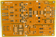
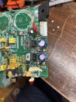
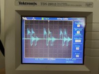
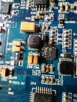
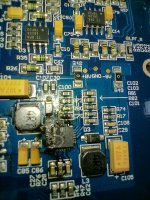
I acquired a Definitive Technology BP7002 speaker with a humming subwoofer. I observed a 120 Hz tone coming from the sub amp outputs when power was connected. I attempted a repair by replacing the two main power capacitors, as well as four small capacitors near the voltage regulators (see circled caps in picture). After replacing these caps, the amp buzzed loudly and the output signal was "all ****** up" (see scope picture).
Obviously, I screwed something up. But I'm not sure what kind of mistake would lead to this result. I'm about ready to abandon the repair and replace the amplifier, but I wanted to get some input from those more knowledgeable at least.
Obviously, I screwed something up. But I'm not sure what kind of mistake would lead to this result. I'm about ready to abandon the repair and replace the amplifier, but I wanted to get some input from those more knowledgeable at least.
Attachments
FS: PCM63K chips
Selling 4x K-grade PCM63 chips.
Pulled from a Parasound DAC-1600. They were socketed the whole time, so they haven't seen any soldering heat. The pullout was gentle, so pins are pristine.
They've been sitting on anti-static foam the whole time and will be delivered as such in an anti-static bag.
Asking - 40EUR/piece net to me + shipping from Latvia to the seller.
I can also sell a CS8412 in a DIP package pulled from the same DAC for 10EUR.
Sony PS-2250 Startup current draw issue
- By MegaHurts
- Solid State
- 5 Replies
Hi,
Looking for help/suggestions.
I've got a Sony PS-2250 that is blowing the 200ma fuse on startup. Running it through my multimeter, it is drawing about 320-340ma for half a second (both 33/45 startup) and then drops to about 100ma after and runs stable. I've replaced all caps and transistors on speed control board and one bad zener and checked all other resistors/diodes. All is good. The thermistor was pulled and seems in spec and working (120 Ohm @ 25C, rise/lower with temp change), but I will order a new one. The encapsulated component (120 Ohm/0.033uf) I think is good and my understanding is this just filters switch noise and not the cause.
I'd rather not just drop in a 400ma fuse and find a better fix.
Would anybody have an idea?
Bridged output triggering intermittent overcurrent shutdown only on certain frequencies mystery???
Hi all ... this is a 600W Class D Bass guitar amplifier with a strange intermittent problem. The amp behaves fine until certain notes are played, predominantly D3 (147Hz) ... which will trigger the amp module (IC4) shutdown for about 4 seconds.
This is the 2nd one of these that I have had here with the same complaint although I couldn't reproduce the fault on the 1st one so thought that it must be something else in his equipment cutting out. Anyway I can certainly reproduce it on this one. Gains etc. are set well within normal playing parameters & I can reproduce this with different Bass guitars.
So I have traced the problem to the over current detection, when the trigger note plays the window comparator IC15 (LM393) triggers the shutdown on IC4.
All voltage rails are fine, happens with 8 or 4 Ohm loads, IC4 is a 600W Class D module with proprietary in house serial numbers that the manufacturers will not decode here's a link to data sheet for what it's worth: https://docs.rs-online.com/fa4e/0900766b80b0985e.pdf
Speaker (8 or 4 Ohm) connects directly to OUT1 & OUT2 ... normally I'd just immediately replace IC15 (LM393) & IC9 (TS512ID) before carrying on with testing but these are soic packages buried deep in between other components and would require a major disassembly to get to.
So before I do that I'm here to see if anyone can shed more light on how this bridged output works through the current sense resistors and IC9?, this is the 1st bridged Class D amp I've looked at ... also not sure how to go about testing any further to troubleshoot this strange problem ... all suggestions welcome.
INVITE to participate in audio system/streaming service survey...
- By Archimago
- Everything Else
- 1 Replies
Hey guys and gals, I've read many of the discussions over the years although due to time constraints not been able to hang out much unfortunately.
I want to "capture" those of us who partake in the high quality audio hobby to get a sense of who we are and these days whether we stream and how we access music...
The survey will take <5 minutes. Hope you can add to the survey!
Best,
Arch
SURVEY: What audio playback system and/or streaming music service are you using in 2023?
6K13P tube spice models?
- By rafafredd
- Tubes / Valves
- 1 Replies
Hi. I am looking for useable 6K13P russian remote cutoff pentode 9-pin tubes spice models.
Would anyone happen to have it?
Would anyone happen to have it?
Sound insulation and acoustic panels from rock wool or fiberglass wool?
- By nas3000
- Room Acoustics & Mods
- 18 Replies
Hello,
I try to insulate kind of a wardrobe, where is heat recovery unit is hidden. Heat recovery unit is a mechanical air ventilation device built from steel with rotational heat exchanger, which has 3 electric motors inside: 2 for moving the air and one for rotating the heat exchanger itself. That last motor is connected with gearbox and both of them are VERY noisy. Think as a half of washing machine noise or more. That motor was changed by the seller of the device couple of times during warranty, the new ones were silent just for couple of weeks, then again: weird noises. The type of noise is vibrational-mechanical type, like a small drill or slow washing or drying machine.
What I did to lessen the sound:
I have no measures before and after.
Photos:


Sound profile 1m form wardrobe with doors closed and open:


Wardrobe is not air tight and there is no way I can make it.
There is still too much noise coming out, and if we think machine is a noise source, then we also can think that inside of a wardrobe is like a small room.
What I want to do is to glue some additional automotive soundproofing material, of felt type but... specialized is both expensive and supply chain issues also present.
Plan B is to glue some homemade rockwool acoustic panel on the front of machine as sound blocker and there is also a room for 1 another acoustic panel type absorber on 1 of the inside walls of closet. Around 10-12cm thickness is most space in front for noise blocker and 5-6cm on the side wall absorber
Questions:
My doubts about the rockwool got stronger after seeing this video:
Login to view embedded media
Whyyyy???? How????
Because glassfibers are longer than rockwool? Because of flufyness? Because fibers are thinner? Will dense glassfiber work too?
It is a sound of 1000Hz, and not much science behind it, but... the result is way too good for glassfibers.
Both materials are sold in bulk, and I do not want to waste money and material which will be not used after, so if someone already tried both, please share your findings.
The most I want to block 160-220Hz spectrum.
I try to insulate kind of a wardrobe, where is heat recovery unit is hidden. Heat recovery unit is a mechanical air ventilation device built from steel with rotational heat exchanger, which has 3 electric motors inside: 2 for moving the air and one for rotating the heat exchanger itself. That last motor is connected with gearbox and both of them are VERY noisy. Think as a half of washing machine noise or more. That motor was changed by the seller of the device couple of times during warranty, the new ones were silent just for couple of weeks, then again: weird noises. The type of noise is vibrational-mechanical type, like a small drill or slow washing or drying machine.
What I did to lessen the sound:
- I built a wardrobe type box for it. Result: now there is definitely less sound amount, but some resonances are more pronounced. Overall still a positive thing
- 5+% of total surface of machine including near that noisy motor, glued with antivibrational butyl rubber sound and vibration deadening material from automotive soundproofing industry. Maybe will glue some more, as only small amount had at hand from last project. Possitive impact, but expected more. I have a feeling, that it dampened the lowest freq sounds, or raised main
- 50+% of total surface glued with some 6mm rubbery foam, also from automotive industry. Not much impact
- Front panel on the inside glued 2 layers of dense synthetic 2mm felt, so 4mm total. Not much impact.
- Inside panels and doors of the wardrobe near the machine glued with pyramid shaped foam. A lot of impact, did not expected much, but it worked well!
I have no measures before and after.
Photos:
Sound profile 1m form wardrobe with doors closed and open:
Wardrobe is not air tight and there is no way I can make it.
There is still too much noise coming out, and if we think machine is a noise source, then we also can think that inside of a wardrobe is like a small room.
What I want to do is to glue some additional automotive soundproofing material, of felt type but... specialized is both expensive and supply chain issues also present.
Plan B is to glue some homemade rockwool acoustic panel on the front of machine as sound blocker and there is also a room for 1 another acoustic panel type absorber on 1 of the inside walls of closet. Around 10-12cm thickness is most space in front for noise blocker and 5-6cm on the side wall absorber
Questions:
- Can they be built the same?
- Is dense stiff rockwool the right material?
My doubts about the rockwool got stronger after seeing this video:
Login to view embedded media
Whyyyy???? How????
Because glassfibers are longer than rockwool? Because of flufyness? Because fibers are thinner? Will dense glassfiber work too?
It is a sound of 1000Hz, and not much science behind it, but... the result is way too good for glassfibers.
Both materials are sold in bulk, and I do not want to waste money and material which will be not used after, so if someone already tried both, please share your findings.
The most I want to block 160-220Hz spectrum.
Batteries for tubes
- By kodabmx
- The Lounge
- 22 Replies
Found this today - thought it was interesting from the perspective that the author has no clue LOL
"Each of these electrodes received power from separate vacuum tube batteries. We can’t say why this was the case, although it does suggest vacuum tubes were energy hungry. The engineers designated the batteries ‘A’ and ‘B’ too, presumably to avoid confusion."
I can bloody well tell you why, and nobody was confused LMAO
https://www.upsbatterycenter.com/blog/vacuum-tube-batteries-remind-us/
One of a kind TQWT
- By Zene
- Subwoofers
- 16 Replies
Hi ... this Voigt is going to be a <200hz sub.
Vas 107 l so box will be big at 3.8 cu ft. Length 72" should be sufficient. Fs 42hz, Qts 0.19.
Main concerns are port size and stuffing. I'm not looking for earthquake bass as apartment living is not good to rattle the neighbors.
Any suggestions will be appreciated.
Zene
Vas 107 l so box will be big at 3.8 cu ft. Length 72" should be sufficient. Fs 42hz, Qts 0.19.
Main concerns are port size and stuffing. I'm not looking for earthquake bass as apartment living is not good to rattle the neighbors.
Any suggestions will be appreciated.
Zene
Rockford Fosgate T2000 problem
good afternoon everyone, I have a problem with a rockfor fosgate T2000 amplifier, little sound and distorted, the operational ICs u300, 301,302, 303 etc have -8.24 volts and 3.45 volts, any suggestions? Thanks in advance
Hello world from a noob
- By afaaone
- Introductions
- 3 Replies
Recently got into tubes. Got me decent 300b SET amp(s). My search for tube friendly speakers landed me here. Specifically I'm very interested in the Mark Audio full range builds. Been reading many threads on the FR builds. So here I am.
I hope to build my own speakers soon. Looking forward to the vast knowledge here for help in the future.
Thanks.
afaaone from Seattle
I hope to build my own speakers soon. Looking forward to the vast knowledge here for help in the future.
Thanks.
afaaone from Seattle
Amber Model 4550 Audio Frequency Analyzer?
- By scotty-o
- Equipment & Tools
- 0 Replies
Hello! I stumbled onto this forum searching for a manual and schematic for an Amber Model 4550. I have one at the studio where I work and would love to get it working again. I can find info on the 3501 distortion analyzer (which we use daily) and other Amber models but the 4550 has been elusive.
Great to see folks here talking about Amber stuff!
With that said, does anyone have a line on the Amber Model 4550 Audio Frequency Analyzer service and user manuals? It would be a great help in getting this piece back in action.
Thank you so very much 🙂
Great to see folks here talking about Amber stuff!
With that said, does anyone have a line on the Amber Model 4550 Audio Frequency Analyzer service and user manuals? It would be a great help in getting this piece back in action.
Thank you so very much 🙂
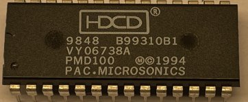
PMD100 HDCD chip
2 x Pacific Microsonics PMD100 for sale. $100 + pp at cost.
Regards
RMalmin
Regards
RMalmin
Attachments
Late intro from San Luis
- By Enochrome
- Introductions
- 2 Replies
Greetings everyone. I have actually been on this sight for a number of years, designing some Nelson and Wayne’s kits, yet I never introduced myself. I have recently moved from Los Angeles to San Luis Obispo two month’s ago. I’m taking a work break for a little bit and wanted to get back into learning electronics. I wanted to thank all the members who have helped me in the past and say a formal Hello!
P3A PCB wanted
I had the good (or bad) idea of reading Sakis' thread on the P3A comparison and now I'm taken, so I'm looking for a pair of PCBs to build a P3A, so if anyone has it in stock, thank you to let me know.
PS: I have neither the time nor the inclination to make my own PCBs ; ) .
PS: I have neither the time nor the inclination to make my own PCBs ; ) .
Inductor (?) with Center Taps
- By bedrock602
- Multi-Way
- 34 Replies
I would like to clone a pair of crossovers for my JBL L55 speakers. The current crossovers have what appears to be inductors with two center taps. I would like to replicate them with discrete components. I suppose I could measure the inductors to determine the values of the taps but my LCR meter for some reason does not do L or C. The x-over in question is the LX15 which only gives one value for the inductor. The LX4-1 controls the same drivers but in a smaller enclosure, the schematic for it has a little more info on the center taps ( -3 and -6) but I'm unsure of its meaning. Help please.

FS: HypnoTised AD797 MC phono stage
- By Thomas Giz
- Swap Meet
- 3 Replies
Up for sale HypnoTised AD797 MC phono stage; fully populated and working board + power supply + transformer. What you see is what you get 🙂
Asking SOLD ! shipped to lower states.


Asking SOLD ! shipped to lower states.
DIY audio interface and MIDI?
- PC Based
- 2 Replies
I had a bit of a look online and there were some previous attempts that I came across, but nothing solid. I am looking for something a bit different too. Is anyone aware of a means of making a DIY setup? A setup or parts of something like this may be of interest to others? For me, it's about family fun. The three and soon to be four of us 🙂 love jamming along to old songs with instruments and mics, and we want to try making our own versions in reggae and recording the instrumentals for karaoke. More live type things than the regular production style use of these gear
Scenario is:
DAW
https://www.akaipro.com/akai-fire
https://www.akaipro.com/mpk-mini-mk3
PC FL Studio with Akai FIRE plus Akai MPK Mini Mk3 for complete FL Studio control side by side. The FIRE for sequencer, transport and menu with the way that matches the FL screen with its pads and four encoders and the Mini for the way that matches the individual VST keys and controls with its keys, eight playing pads and eight encoders. Both have been criticised for being short on controls, but for my use they come together very well on the desk. I have the FIRE already, but yet to order the Mini. It also comes with a FL license and FL Mobile as VST plugin. Pretty much a comprehensive FL home studio setup that can also sync a portable setup, which is next
VST instrument
https://www.akaipro.com/mpk-mini-play
iPad 9 gen with FL Mobile and Akai MPK Mini Play Mk3 as controller. We have this already and is the new student level studio that I just set up for my daughter as well as a sister and her little son in Fiji. My daughter is looking forward to being the teacher 😀. Can her digital iOS Instrument feed into the DAW over USB MIDI?
Plus
Bass guitar, flute, vintage keyboard and three mics
This is all standard stuff and can be done with something like this from Ali or a brand name one from the music shop
https://www.aliexpress.com/item/1005005062825028.html?spm=a2g0o.cart.0.0.570638daNdzeH5&mp=1
The difficulty is with how we use it. We already have tube based pres for our bass and mics, as well as tube based headphone amps. There are duplicate functions in the pre stages of a regular interface and our pres too
Aims
Bass player - a mono audio line into DAW for bass and one for his mic. MIDI foot control of live effects for the snare on the sequencer pads. MIDI foot control of a VST synth arp in the DAW. MIDI foot control of the effects for other channels. A personal headphone channel from the DAW
Flute player - a mic line for her into the DAW and a stereo line for her vintage keyboard. A personal headphone channel from the DAW
iOS synth player - a mic line for her into the DAW. A personal headphone channel from the DAW
To save some money and to avoid duplicating all the pre stages, I am inclined to try a high quality external HT sound card that has three pairs of audio out RCAs to feed the three headphone amps. Use the analog out on the PC internal sound card for the master monitor and the analog input pair for each mic. An ADC for the vintage keyboard on the optical in of the internal sound card
This leaves one mic short, but maybe a USB mic can be used here?
I have been able to previously use asio4all to run headphone outs and monitor and master outs on a PC with virtual DJ before, so FL should be more configurable
I need a plan for the foot controls. That's echo and delay effects for the snare, effects and control of an arp, effects for the other channels. Maybe four rows of expression controls on a custom board? I am thinking that a rocker style foot control will allow the amount dialled to stay there like a knob. Rotary encoders on their sides, for delay, echo and levels, plus foot buttons for arp switching?
I look forward to hearing thoughts on the audio routing and MIDI setup
How to test this transformer
- By Chrisr3521
- Power Supplies
- 4 Replies
With just a circuit board containing these connections lighting a dim bulb tester hard on I need to test just the main transformer, to separate this would I connect 230v live to AC5 and neutral to AC3?

Topping D50 salvage
- By Stairfly
- Digital Line Level
- 2 Replies
Hi All. I've got a Topping D50 with a burnt out DC/DC converter. I think I can replace the converter chip TPS65130, but more concerned with putting in new resistors, which is going to be very fiddly, and what damage has been done to the circuit board. Rather than the replacement and repair route is there a way of bypassing the whole DC/DC convertor with a separate unit?
I'm a novice but happy to try a bit of soldering/ desoldering for the learning experience.
The unit still powers on ok, but no sound output. What do you think? Seem to be a lot of valuable components here, is there any way to salvage something, or is this just a coffee mat?
I'm a novice but happy to try a bit of soldering/ desoldering for the learning experience.
The unit still powers on ok, but no sound output. What do you think? Seem to be a lot of valuable components here, is there any way to salvage something, or is this just a coffee mat?
Attachments
Can anyone explain this crossover to me please?
This is the wiring diagram for a pair of Sony SS-H3500 (supposedly a 3-way) speakers, but I don’t get it at all. They’re 6 ohms.

For Sale Audiotechnology 18H52-17-06-SD several pairs
Hello. I have some Audiotechnology 18H52-17-06-SD midwoofer pairs (up to 5 pairs) in the shelf that will be for sale for another DIYER to use them. Please, read the whole thread.
18H52-17-06-SD with trimmed frame (made in AT factory). Intended to be used in D'apollito arrangement, I have up to 3 pairs for sale. Original packaging. Very good condition.
2 units: 330€
4 units: 625€
6 units: 900€


18H52-17-06-SD standard frame. I have 2 pairs: one of them is 4 Ohm VC and one another is 8 ohm VC. Very good condition both. Original packaging
2 units (4 or 8 ohms): 350€

All the drivers had been tested and used. There are some screw marks in the mounting holes but nothing visible after screw
Prices doesn't include PP feed not shipping.
18H52-17-06-SD with trimmed frame (made in AT factory). Intended to be used in D'apollito arrangement, I have up to 3 pairs for sale. Original packaging. Very good condition.
2 units: 330€
4 units: 625€
6 units: 900€
18H52-17-06-SD standard frame. I have 2 pairs: one of them is 4 Ohm VC and one another is 8 ohm VC. Very good condition both. Original packaging
2 units (4 or 8 ohms): 350€
All the drivers had been tested and used. There are some screw marks in the mounting holes but nothing visible after screw
Prices doesn't include PP feed not shipping.
For Sale Satori TexTreme MW16TX-8
For sale a pair of Satori TexTreme MW16TX-8 in very very good condition. Only some marks in the inner holes from being screwed
Just measured and tested for 20 hours maximun.
Retail price is 290€ each, 580 the pair.
Asking 350€+ shipping + PP fees


Just measured and tested for 20 hours maximun.
Retail price is 290€ each, 580 the pair.
Asking 350€+ shipping + PP fees
Bryston 3B-ST and 2B, need help with bias and offset
- By noviygera
- Solid State
- 5 Replies
Greetings!
I had no luck getting help from Bryston, not sure why they are not responding. I am preparing these Bryston amps for an install at a venue and I need to make sure they are running properly. So, I am reaching out for help here.
I have a working 3B-ST and need some help with the following: where and how do I check and set the "bias" and "offset"?
Also, I have a used 2B-LP and need to confirm the proper "bias" voltage, as it seems to be running hot.
Also, I have a used 3B (non ST), need to confirm the "bias" voltage.
Thanks!
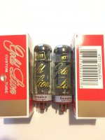
For Sale Tubes KT77 x 2 Genalex (Gold Lion) for sale
I will sell KT77 x 2 Genalex (Gold Lion) matched pair. Played about 50 hours. More info PM.
Price: 100 Eur
Price: 100 Eur
Attachments

Looking For a Good Function Generator to Produce Square waves
- By Mikerodrig27
- Equipment & Tools
- 62 Replies
I have been reading but haven't been able to wrap my brain around what to get. I would like a piece of equipment to test square waves at 1khz and 10khz for testing amplifiers for oscillation etc.
Looking for something in the $100-$200 range. I was hoping some of you may have some good suggestions. Maybe something I can order on Amazon. Sorry for the newb request. This will be my first Function generator and I feel like I am running around in circles trying to get something to produce a nice square wave to test with.
Thank you!
G. Rankin 45 DCCCS amp mods
- By EZ80
- Tubes / Valves
- 3 Replies
I build this amp years ago and it was excellent! I want to have another go at it with a few changes, like doing away with the ECL82, this question is about the pentode section forming the CCS, other than a socket change and filament current, can I swop in a 6v6g, with no other changes. want to use a ST tube the same size as a 45, so there may be other options. Thanks John
Attachments
Bottom plate for tube build?
- By ChrisM91
- Construction Tips
- 10 Replies
I am building a tube power amp and I am doing the classic aluminum top plate and wood sides.
On these builds do people usually also add a bottom plate to enclose the electronics and seal up the amp, or is the bottom left “open”?
I can see pros and cons of both. If I added a bottom plate I’d have to perform the extra work and have it cut out so there is ventilation.
On these builds do people usually also add a bottom plate to enclose the electronics and seal up the amp, or is the bottom left “open”?
I can see pros and cons of both. If I added a bottom plate I’d have to perform the extra work and have it cut out so there is ventilation.
SMPS powered small cl. A amp
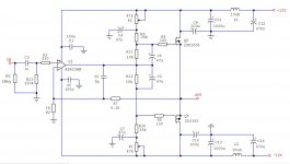
Couple of months ago I got two nice SMPSs (12V/6A) originating from discarded computer network equipment and since they are nice, clean and quiet (less than 1mV of 55kHz noise after output filter, at full load) I thought I could use them as a power supply for a small class A power amp (I never used SMPS in a power amp before).
Just to test it I chose the composite topology - OpAmp at input and source follower with Lateral MOSFETs at output. AD823 was my choice because it swings rail to rail. Also it has JFET input (low offset, high Zin) and later I discovered that it sounds really nice in this combination.
To extend the voltage swing of the output stage I bootstrapped the MOSFETs' Gates with C2, C6 so the amp clips at 23Vpp with 24.4V power voltage (the rails are actually 12,2V) which translates into 8W @ 8R i.e. 16W @ 4R.
Output MOSFETs are biased through voltage dividers (P1+R10)/R12 and (P2+R9)/R11.
Biasing starts with max. value of pots (lowest bias). Pots are turned slowly and alternatively (like described in F5 manual) until we reach (depending on your heatsinks and speakers) Id of about 0.5 - 0.7A and DC offset at the output of 0mV (put 0R1 serially in one of the power rails and measure 50-70mV accross it. Remove it after biasing). We use Laterals without source resistors so we can exploit their square law transfer characteristic and the exact bias current value is not that important but you can play with it.
DC offset is very stable, thanks to OpAmp's feedback loop which includes MOSFETs (meaning very low Zout i.e. high damping factor too). The pic shows MOSFETs and voltage dividers as point to point build on the heatsink and the chip is on the perfboard by the PSU so I adjusted the bias and the DC offset before I powered the chip and it stayed stable after inclusion into feedback loop. C5 (SMD) is soldered directly between the chip socket's pins. All electrolytic caps are 16V Japan made NIC (NRSG series - very low impedance): NRSG Series Page
The amp is very stable and fast and sounds much better than I expected. Most of all, it's an easy build. Have fun with it...
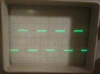
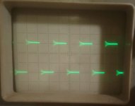
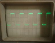
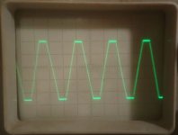
Pics show:
- Square wave 15V_pp 20 kHz @ 5R load (5V/div, 20uS/div)
- Square wave 15V_pp 20 kHz with 100nF pure capacitive load (5V/div, 20uS/div)
- Square wave 15V_pp 90 kHz @ 5R load (5V/div, 5uS/div)
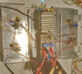
- Prototype build (when put together the amp measures 22cm x 22cm x 10cm - heatsinks are 22cm x 10cm x 4 cm and they go to about 20 degrees C. above the ambient temp.)
- Schematic diagram (every channel has its own power rails filter)
- Hard clipping of 20 kHz triangle wave (5V/div, 20uS/div)
P.S. Dobrivoje, thank you for the heatsinks !
Just to test it I chose the composite topology - OpAmp at input and source follower with Lateral MOSFETs at output. AD823 was my choice because it swings rail to rail. Also it has JFET input (low offset, high Zin) and later I discovered that it sounds really nice in this combination.
To extend the voltage swing of the output stage I bootstrapped the MOSFETs' Gates with C2, C6 so the amp clips at 23Vpp with 24.4V power voltage (the rails are actually 12,2V) which translates into 8W @ 8R i.e. 16W @ 4R.
Output MOSFETs are biased through voltage dividers (P1+R10)/R12 and (P2+R9)/R11.
Biasing starts with max. value of pots (lowest bias). Pots are turned slowly and alternatively (like described in F5 manual) until we reach (depending on your heatsinks and speakers) Id of about 0.5 - 0.7A and DC offset at the output of 0mV (put 0R1 serially in one of the power rails and measure 50-70mV accross it. Remove it after biasing). We use Laterals without source resistors so we can exploit their square law transfer characteristic and the exact bias current value is not that important but you can play with it.
DC offset is very stable, thanks to OpAmp's feedback loop which includes MOSFETs (meaning very low Zout i.e. high damping factor too). The pic shows MOSFETs and voltage dividers as point to point build on the heatsink and the chip is on the perfboard by the PSU so I adjusted the bias and the DC offset before I powered the chip and it stayed stable after inclusion into feedback loop. C5 (SMD) is soldered directly between the chip socket's pins. All electrolytic caps are 16V Japan made NIC (NRSG series - very low impedance): NRSG Series Page
The amp is very stable and fast and sounds much better than I expected. Most of all, it's an easy build. Have fun with it...
Pics show:
- Square wave 15V_pp 20 kHz @ 5R load (5V/div, 20uS/div)
- Square wave 15V_pp 20 kHz with 100nF pure capacitive load (5V/div, 20uS/div)
- Square wave 15V_pp 90 kHz @ 5R load (5V/div, 5uS/div)
- Prototype build (when put together the amp measures 22cm x 22cm x 10cm - heatsinks are 22cm x 10cm x 4 cm and they go to about 20 degrees C. above the ambient temp.)
- Schematic diagram (every channel has its own power rails filter)
- Hard clipping of 20 kHz triangle wave (5V/div, 20uS/div)
P.S. Dobrivoje, thank you for the heatsinks !
Attachments
WTB: Balanced MiniDSP Flex
Hey All,
Working on a birthday present to myself and the Flex would really make things fun.
Might anyone have one they are looking to unload?
Cheers!
Working on a birthday present to myself and the Flex would really make things fun.
Might anyone have one they are looking to unload?
Cheers!
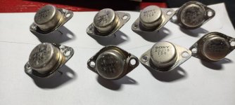
FS Sony Vfet set from TA-5650
I dismantle these from a broken amp many years ago. Not intend to do anything on it.
I would like to sell USD250 include ship. Paypal family with no fee.
Im not very familiar on these, so i only did a rough measurement on the 2 legs. 7 pieces of them measure a legs with chasis have 1 to 100 ohm random. one of them both leg measure have 1 ohms n 20 ohms.
Please evaluate on these before buying and i provide no return and warranty. thanks
Attachments
Sony VFET Round 3
Using the VFET Round 3 output Stage, I have built the two Bulwark boards. Two P-VFET OS2 and two P-VFET OS2. these boards are for revision 2.
When I check the 'as build's' and wiring diagrams I only see one of the N and P board used. What am I missing?
When I check the 'as build's' and wiring diagrams I only see one of the N and P board used. What am I missing?
Capacitance meter
- By Jcris
- Equipment & Tools
- 16 Replies
Hey,
I’m looking for a recommendation for a capacitance meter. Something accurate and not too expensive, if those aren’t mutually exclusive. This will be used only occasionally for diy work. Initially it will be used to accurately measure capacitors used in an electronic crossover. Less than $100 would be ideal
Thanks
Zip cord for speaker test
- By Pano
- Everything Else
- 421 Replies
This thread will document a test of speaker cable stored energy using four bundled pairs of zip cord, also known as lamp cord. In this case it's 18 AWG SP-1, which is the thin insulation version.
The test was proposed here by jneutron:
https://www.diyaudio.com/forums/everything-else/193100-speaker-cable-myths-post6617073.html
The test was proposed here by jneutron:
https://www.diyaudio.com/forums/everything-else/193100-speaker-cable-myths-post6617073.html
Big dip between active and passive filter around crossingpoint?
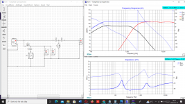
Hello folks
Have build a DIY MTM with 2 x Audax HM210Z10 and a Mundorf AMT29CM1.1.
Woofer is 3 X Peerlees XXLS 12 inch per side vented in 102 liter netto, tuned at 22 hz
Xoverpoints are 340 and 1850 Hz, and i use a Active filter for both high and low feeding 2 stereoamps.
So woofers get all under 340 hz direct from active filter/amp, and midrange/top get everething over 340 hz from active filter/amp, but have a highpass filter.
Audax midrange have a 2 order filter and Mundorf AMT have a 3 order filter (from 1850 hz).
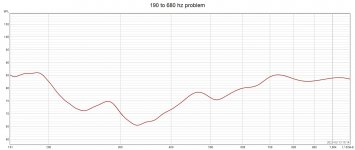
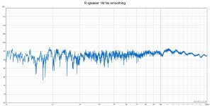
The measurements over 1K looks quite good, but i have a terrible deep long 19 dB dip from about 180-680 hz?
Don´t know where to start trubbleshooting?
Can´t do much under 340 hz sinse the active filter does "everything" for the woofers, and don´t understand why midrange curve is "so bad" from 340-680 hz, but same time is good from 1K ?
Anyone have some suggestions?
This is ihow it looks in XSIM, and yesterdays measurements.
Best regards John
Have build a DIY MTM with 2 x Audax HM210Z10 and a Mundorf AMT29CM1.1.
Woofer is 3 X Peerlees XXLS 12 inch per side vented in 102 liter netto, tuned at 22 hz
Xoverpoints are 340 and 1850 Hz, and i use a Active filter for both high and low feeding 2 stereoamps.
So woofers get all under 340 hz direct from active filter/amp, and midrange/top get everething over 340 hz from active filter/amp, but have a highpass filter.
Audax midrange have a 2 order filter and Mundorf AMT have a 3 order filter (from 1850 hz).
The measurements over 1K looks quite good, but i have a terrible deep long 19 dB dip from about 180-680 hz?
Don´t know where to start trubbleshooting?
Can´t do much under 340 hz sinse the active filter does "everything" for the woofers, and don´t understand why midrange curve is "so bad" from 340-680 hz, but same time is good from 1K ?
Anyone have some suggestions?
This is ihow it looks in XSIM, and yesterdays measurements.
Best regards John
Attachments
"The Wire AMP" Class A/AB Power Amplifier based on the LME49830 with Lateral Mosfets
- By opc
- Solid State
- 2642 Replies
"The Wire AMP" Class A/AB Power Amplifier based on the LME49830 with Lateral Mosfets
A new run of these boards is now available! Please see the following thread for details:
http://www.diyaudio.com/forums/soli...ble-here-bal-bal-se-se-lpuhp.html#post3516741
Hi Guys,
There's a new addition to "The Wire" series of projects I've been working on lately.
It's push-pull amplifier based on the LME49830 front end which drives a pair of ACD101NDD and ACD103PDD lateral mosfets. It's immensely versatile in that you can run essentially any rail voltage from about +/- 10V up to about +/-90V on the mosfets and get anywhere from 1W to 400W of output depending on the load and the rails. This is an amp that can be tailored to any situation.
You can also run the amp in class A, class AB, or class B if that's your thing.
For the input, you can run either fully balance, or with just one 0R jumper it can be configured for SE input. You can run the amplifier AC or DC coupled. There are separate supply options for running the LME49830 on higher rails than the mosfets which improves efficiency and allows for a good regulated supply for the front end. Alternatively, with a pair of 0R jumpers, you can run just a single +/- supply for both the LME and the mosfets.
The board is small enough to fit pretty much anywhere, and all you need to provide is the power supply and the heatsink! I've even got an optional regulated supply board for the LME section.
I've attached the schematic, the Excel worksheet to calculate power outputs and rails, along with the layout and a BOM.
The PCB will be a 3 layer design with a ground plane in the middle and signal routing on either side. The LME has its own heatsink and the two mosfets are mounted on a user supplied sink off the end of the board. The board measures 2.45" by 1.6" and has all the required mounting points.
I will also be running a kit with this that includes all of the parts required to build a complete amplifier. All the user will need to supply is the main heatsink and the power supply.
PCB's are going to be $12 per channel, and a full kit including all 0.1% thin film resistors, and the best caps available for this application will be $78 per channel. I've attached the price list for the amplifier kit which contains all the details.
There will be 50 boards made available, and it will be first come first serve. Please post here if you're interested in a just a board, or a board and a kit, along with how many of each. Any technical question are welcome as well!
Measurements to follow!
EDIT - 27/05/2012
The schematic and layout below are incorrect. For the updated information, along with the assembly guide, please see this post:
http://www.diyaudio.com/forums/soli...-lme49830-lateral-mosfets-75.html#post2920157
Cheers,
Owen
Attachments
Individual PCB sockets
I want to be able to compare some different component values without having to solder / desolder each time. Can someone point me to some good quality individual PCB sockets?
Easier Calculation of some LC Resonant Circuits
- By jhstewart9
- Tubes / Valves
- 6 Replies
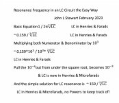
Easier Calculation of some LC Resonant Circuits John L Stewart Feb 2023
Keeping track of all the zeroes can be confusing when calculating resonant frequency of LC circuits. Here is a simplification of the basic equation that can help.
This version is setup to cover capacitors from One nanofarad to several microfarads. And chokes from one mH to several Henries.
The basic resonance equation is 1 / 2*PI*root LC.
To an accuracy of better than one percent 1 / 2*PI is simply 0.159. The equation becomes 0.159 / root LC
Multiplying top & bottom of this by 10^3 (1000) results in the numerator (top) is now 159.
On the bottom (denominator), taking the root of the 10^-6 in the cap micro farad gets a 10^-3 (0.001).
That cancels the multiplier of 10^3 (1000) in the denominator. And the equation for resonance becomes simply 159 / root LC, where L is in Henries & C is in microF.
As a typical example a power supply filter might consist of a 5H choke & 40 microF cap. What is the resonant frequency?
Calc the root of 5*40, By eyeball looks like ~14. 14 squared is 196. Close enough. 14 fits into 159 a bit more than 14 times.
15 Hz is the resonant frequency, in this case all done without a calculator.
Attachments
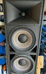
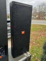
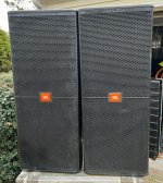
For Sale JBL SRX 722 dual 12" passive biampable speakers- pair of TWO with covers
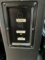
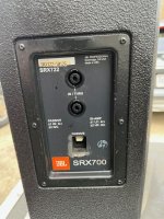
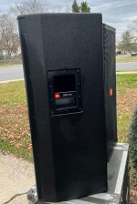
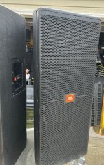
Item for sale is a nice used pair of JBL SRX 722 passive two way dual 12" speakers - Excellent clean sounding cabinets- all drivers are correct JBL - previous owner touched up / resprayed the cabinets in duratex, looks very nice, grills are good but not mint. Owned by professional sound company on BSS processing and Macrotech power. Price is for the pair of TWO. I have another identical pair available as well. On one of these cabinets the label on the input plate or the input plate itself has been replaced, it is the correct original JBL part, I pulled it to check. Both come with very nice covers in great condition. These are ready to go. I would prefer local pickup from woodbridge va 22192/ I do not have original box or packing to ship.
price:899$
free shipping
Brand: jbl
Model: jbl srx 722
price:899$
free shipping
Brand: jbl
Model: jbl srx 722
Attachments
-
 s-l1600 - 2022-12-27T173125.752.jpg340.2 KB · Views: 395
 -
 s-l1600 - 2022-12-27T173120.893.jpg365.1 KB · Views: 431
 -
 s-l1600 - 2022-12-27T173115.528.jpg386.9 KB · Views: 348
 -
 s-l1600 - 2022-12-27T173111.196.jpg430.1 KB · Views: 365
 -
 s-l1600 - 2022-12-27T173107.082.jpg377.7 KB · Views: 732
 -
 s-l1600 - 2022-12-27T173102.938.jpg533.6 KB · Views: 619
 -
 s-l1600 - 2022-12-27T173057.077.jpg734.8 KB · Views: 255
Replacing fuse bulbs in vintage speakers? Modern alternatives?
- By JimBanville
- Multi-Way
- 53 Replies
I've got a pair of Ohm Acoustics speakers from the 80's that have two fuse bulbs in the crossovers. One bulb is blown in each crossover. Ohm is notoriously tight lipped about giving out info on diy repairs of their speakers. They want you to send them to them for big repair bills. Not interested. Anyway, I need to find a replacement or simply a modern alternative to the blown bulbs. I've only taken one crossover apart. The impedance of the good bulb is 2 ohms. I've found several other fuse protection blubs online that look identical to mine, but with varying ratings, and none list impedance. The only markings on mine are "C 9" stamped in the glass end, and an "S" stamped into the other side of the same end. I would assume that a speaker engineer would factor in the impedance of the bulb when designing the crossover, yes? Although it is my understanding that the impedance of these bulbs does increase as the wattage they receives increases. The bulbs are in the fabric insulation.

MM74HC mystery project -- what is it?
- Digital Line Level
- 10 Replies
I built this many years ago, on a small proto board (both photos, same device from different angles). All smd components, based on the MM74HC quad 2-input NAND gate.
Some kind of digital audio tweak (reclocker, etc???).
Anyone have a guess on what it may be?
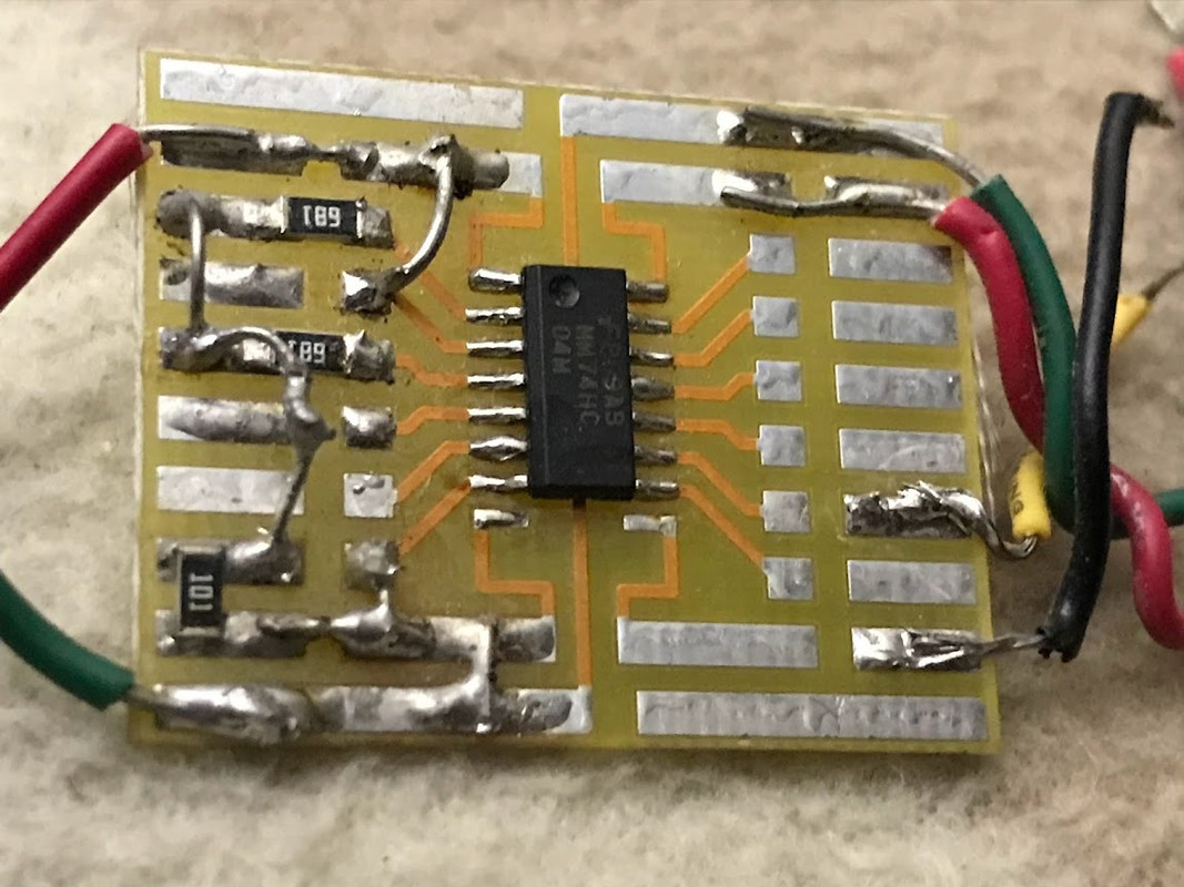
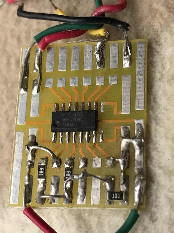
Some kind of digital audio tweak (reclocker, etc???).
Anyone have a guess on what it may be?
B&W AS6 subwoofer..amp topology questions
- By ants2au
- Solid State
- 8 Replies
I have this sub, that has blown output fets and fuse..
I have replaced both fets, and to be on the safe side, I also replaced both opamps and Q610
I hooked up an amp meter on the fuse holder, and slowly brought up the voltage on a variac.
no sooner there is about +-6v dc on the rails, the current being drawn is through the roof..
There is still something not right.
‘I must confess, I have not seen this amp topology before, so I don’t know what to start looking for at the moment.
I really do need some guidance, maybe how it should work as a start.. it could give clues as to what is else is wrong.
- Does it need a load connected to work?
- What does Q605 actually do here? In conjunction with IC602.
- There are two BC601 marked on the circuit..one of them has a link
- And if I remove pin6 of IC601, no current is drawn..cool.. but obviously no output either
.")
Attached is a schematic, but can also be found on hifiengine.
Playing at Discrete Op-Amp Design
- By kevinkr
- Analog Line Level
- 52 Replies
The OP and at least one participant of this cool thread asked for details on some of my discrete op-amp designs.
That thread is here: Purple Gain:a discrete opamp
So a little context, these were designed for my tape amplifier project. There are 4 variants; one is yet untested, and I will share the one I am currently using in the front end in this post.
They have LSK389 dual jfets in the front end, but are otherwise pretty traditional.
The version I have shared is the high gain iteration that is used in the first stage of the tape amplifier which needs a lot of gain at low frequencies.
I've attached the .asc file.
Attachments
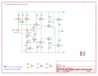
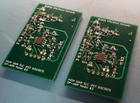
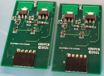

iFi Audio NOS 6922 Wanted
- By bigskyaudio
- Swap Meet
- 15 Replies
Looking for a new pair of iFi Audio NOS 6922 tubes (GE 5670 with adapters). Please pm me.
For Sale Tubes 2A3 x 2 Sovtek for sale
I will sell 2A3 x 2 Sovtek matched pair. Played about 100 hours. More info PM.
Price: 200 Eur
Price: 200 Eur
Attachments
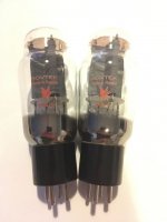
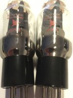
PCM56 +Raspberri Pi?
- By ZoltanChivay
- Digital Line Level
- 2 Replies
Hi
A friend gave me some old CD players. Inside I found some nice DAC chips like TDA1541A , 2* PCM56 , 2* PCM1702.
I don't use CDs anymore. My source of music is Raspberry Pi + Kali reclocker + DAC (I have 3 of them) System is Moode.
I'm not familiar with digital technology, so I have a question about PCM 56
. Is it possible to apply this DAC to work with the I2S signal from Rpi+Kali? On the internet I found solutions for TDA1541 and PCM1702.
I am able to design a pcb and solder it. Unfortunately, the DAC design is beyond my skills.
Thank you and greetings from France
Sonic Frontiers SFCD1 Player Issue
- By Champ
- Digital Source
- 12 Replies
Dear community, I have come for some sound advice.
I have a Sonic Frontiers CD1 with the left channel creating a wooshing noise heard mostly through the tweeter because of the higher frequency. The noise only happens when music is playing and is volume dependent, gets louder as the volume is increased/decreased. The music is playing flawlessly, with overlaying sound rushing or whooshing, only way I can describe it. Several months ago I did a clean and lube of the infamous Philips CDM12.4 tray/pickup as the grease was dried up. Has been working flawlessly since and this issue just happened out of nowhere. I thought it could be a dirty connection in the left channel output relay. I replaced this and still have the issue. Could this be the DAC. If it is I am kinda screwed as that is DAC is no longer available. Any help troubleshooting this stunning sounding player and keeping it out of landfill would be much appreciated.
I have a Sonic Frontiers CD1 with the left channel creating a wooshing noise heard mostly through the tweeter because of the higher frequency. The noise only happens when music is playing and is volume dependent, gets louder as the volume is increased/decreased. The music is playing flawlessly, with overlaying sound rushing or whooshing, only way I can describe it. Several months ago I did a clean and lube of the infamous Philips CDM12.4 tray/pickup as the grease was dried up. Has been working flawlessly since and this issue just happened out of nowhere. I thought it could be a dirty connection in the left channel output relay. I replaced this and still have the issue. Could this be the DAC. If it is I am kinda screwed as that is DAC is no longer available. Any help troubleshooting this stunning sounding player and keeping it out of landfill would be much appreciated.
Wharfedale RS10 subwoofer is restarting at high volume
- By drakejest
- Subwoofers
- 0 Replies
So i have a Wharfedale RS10 5 in 1 taken out from storage (for about a year). The subwoofer has been misbehaving lately. So the subwoofer is an active subwoofer that needs to be connected to the wall and takes in a subwoofer signal from an amp.
So at 50 (out of 99) volume, i could not feel the subwoofer, very quiet it might as well been off. At 75 volume is where i like it, the base is strong, but here comes the problem. With songs that have a lot of base in them, after a while the display will start to flicker (the base is still there) like its not provided enough power. At 85 volume is a bit more crazier, again the base feels strong and when the heavy continuous base of the song comes the subwoofer flat out shutdowns and restart. It will not play anymore, unless it is restarted by turning off the wall power switch and turning it on again.
Given that i suspect a blown capacitor or the transistors are failing. It also does not sound like a blown speaker though it can kick, but not for long, like its not being fed with enough power. That is just my opinion though. I would like to attempt to repair it, i have experience in electronics and comfortable soldering/de-soldering stuff, but this will be my first time repairing audio electronics. Glancing at the circuit there doesn't seem to have a component that catastrophically failed.
Has anybody experienced this before? What could it possibly be? Before i begin dismantling the stuff i would to hear your guys opinion first 🙂
Build a crystal oscillator from schematic thru prototype construction and testing - DIY
- Digital Line Level
- 2 Replies
Interesting test board.
Login to view embedded mediaThis video takes you through the process of building a circuit from a schematic, including circuit board preparation, soldering components using Manhattan style construction and then testing it. It uses a buffered Colpitts Crystal oscillator as the example.
nA CCS mystery
- By Elvee
- Equipment & Tools
- 90 Replies
I am currently building a cheap and dirty gigaohmeter.
The principle is pretty simple and basic: a precision CCS feeding the R.U.T. followed by a unity gain buffer.
No rocket science involved, but for 100G full scale with a 10V output, a current of 0.1nA is required as a stimulus.
Everything works as expected for lower ranges, but for 100G, the CCS fails.
Obviously, there are numbers of potential issues regarding leakage, etc., and I did my homework accordingly: I carefully selected an tested all the components involved: the BSP92 was chosen for its sub pA leakages between all electrodes, the TLC272 sample was selected for the same reason, etc.
I used guarding for the output, but it doesn't seem to be an issue: the main problem is the CCS. It should deliver 0.1nA, but it delivers nothing.
I measured the current through Rx and R2, they were identical and zero. When R2 is reduced to 250Meg, a current of 0.2nA flows through it and the Rx, and the indication is consistent.
With the total 1G of reference, no current flows, and the output of the TLC272 goes high, trying to reduce it even further.
At 1nA, its output is ~0.7V below the +12V rail. The 3V difference between the 15 and 12V rails allows the opamp to work comfortably.
There must be a leakage unaccounted for somewhere, but I am unable to locate it.
I have measured the actual gate current of the BSP92, an it's below 1pA, as is the -input current of the TLC272.
The reed relay has been screened too, and anyway in the 100G condition, all its electrodes are +referenced, meaning it could only increase the current, not diminish it.
The problem is clearly the CCS, but I don't see where it stems from.
Could be the board: it is an epoxy perfboard, but it doesn't seem to have issues: nothing measurable, and I milled it to isolate the critical nodes, and I isolated the -input of the opamp to connect it directly to the source of the BSP.
Celestion HF1300 assembly
Hi all,
I am about to replace the voice coils of a pair of burntout Celestion HF1300 from the seventies.
I will probably be successful in the coil replacement, but I realise I have made a bad mistake in the disassembly.
I forgot to write down / take an image of the order of the stack of paper / phenolic rings holding the membrane.
I have:
1 thick phenolic resin composite ring
1 thick cardboard ring
2 thin cardboard rings
1 phenolic diaphragm w. voice coils
1 metal grille
1 magnet assembly
1 plastic housing
What is the order of assembly of the rings?
I hope there is someone still alive that has serviced such archaic parts.
Regards,
BN
Attachments
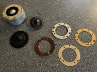
Unlink doesn't work
- By kodabmx
- Forum Problems & Feedback
- 13 Replies
I posted text without formatting, but the forum software parsed the content and included links.
I edited the post, hit the unlink button for each link. I hit save. It did nothing - the links are still there.
Maybe it doesn't work because they are inside a "quote"
https://www.diyaudio.com/community/threads/fake-paypal-scam.395730/post-7270161
I edited the post, hit the unlink button for each link. I hit save. It did nothing - the links are still there.
Maybe it doesn't work because they are inside a "quote"
https://www.diyaudio.com/community/threads/fake-paypal-scam.395730/post-7270161
For Sale Tubes KT77 x 2 JJ for sale
I will sell KT77 x 2 JJ matched pair. Played about 30 hours. More info PM.
Price: 40 Eur
Price: 40 Eur
Attachments
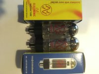
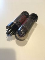
Thoughts on this PSU design?
- By nzoomed
- Power Supplies
- 2 Replies
Been modelling in PSU designer a power supply for an 807 stereo amplifier using a pair of 807s in each channel class AB1 ultralinear.
Im allowing an idle current of 60mA and a max current of 200mA as seen on the screenshots below.
I am aiming for a voltage of 450V, my PT supplies 690V (345-0-345) Im actually beginning to wonder if i might need a slightly higher voltage PT, but overall the models seem to provide enough voltage at low power, you can tweak all the variables all night with this software, but its hard to get the right balance between voltage under full load and when idle or a lower load, lets face it, I guess its nothing to worry about under max power as its not like you run it on full power, but its good to have it provide the most stable voltages across the range.
My main concern was the datasheet for the 866 specifies the primary filter cap at 4uF max, but I find that increasing this value actually helps somewhat.
I get 460V on low load and it drops to about 430V or so under max load.
I can tweak this to provide a lower voltage when idle, but it drops off even more when under load.
Any tweaks anyone could suggest are appreciated, would an RC choke work better with these perhaps?
Idle current:

Max current (im also not entirely sure about the warning message either):

Im allowing an idle current of 60mA and a max current of 200mA as seen on the screenshots below.
I am aiming for a voltage of 450V, my PT supplies 690V (345-0-345) Im actually beginning to wonder if i might need a slightly higher voltage PT, but overall the models seem to provide enough voltage at low power, you can tweak all the variables all night with this software, but its hard to get the right balance between voltage under full load and when idle or a lower load, lets face it, I guess its nothing to worry about under max power as its not like you run it on full power, but its good to have it provide the most stable voltages across the range.
My main concern was the datasheet for the 866 specifies the primary filter cap at 4uF max, but I find that increasing this value actually helps somewhat.
I get 460V on low load and it drops to about 430V or so under max load.
I can tweak this to provide a lower voltage when idle, but it drops off even more when under load.
Any tweaks anyone could suggest are appreciated, would an RC choke work better with these perhaps?
Idle current:
Max current (im also not entirely sure about the warning message either):
Beyma 12B100DB musings
- By geoturbo
- Subwoofers
- 2 Replies
Hello all,
a bit of a newbie here, I would like to exhume from the garage my 12" Beyma 12b100 DB (DB for double bobbin) and would use it with a 45 (net) liter sealed box I have ready to get me going fast, using it as the main subwoofer with my Pawel monitors for 2.1 listening.
I am having already a Behringer dcx2496 to process the preamp analog output and one channel 130W/8ohm class AB amp.
Is anyone having the specifications of this driver maybe? I seem to find the 12b100 specs quite easily but the double bobbin does not seem to be available.
I might try to apply/learn Arta/Limp/Hornresp in the process later on to simulate/optimize the Beyma..
Cheers and beers!
Improve operational preamps
Good afternoon, I introduce myself from Spain, and I would like to ask a question.
I bought a Fosi Audio Box X2 phono preamplifier a month ago, and I have changed the vacuum tubes for better quality ones, noticing a clear improvement in sound quality. I also bought some LM4562 preamps, but the result is not as expected, since it gives the music more clarity but the mids and bass are lost, almost completely.
The standard preamplifiers are the 2068DD, which together are more balanced, but I would like to know if I could improve the result with any other preamplifier model and if so, which one do you recommend?
Thanks and regards.
Amplifier Market Changing
- By Adriel
- Tubes / Valves
- 129 Replies
I am going to build BIB speakers (waiting on help modeling a pair of speakers), got into active versus passive crossovers, then into amplification (searching this forum is dangerous...).
What I keep finding over and over is great performing kits that were under $750USD, especially under $500USD have been discontinued, sometimes with kits four times the cost (ex. Bottlehead Paramour I and II, now there least expensive option is about twice the price).
Why is this?
More interesting is there are a plethora of inexpensive per amplifier kits like the S4. Odd because of the severe difference and without an amplifier, a pre is useless (sometimes a pre isn't even needed apparently).
Thought this be an interesting discussion.
+15v / -15v supply - how to
- By szegedin
- Power Supplies
- 45 Replies
Very basic question, in the spirit of DIY:
I need a supply of +15v / -15v for a preamp.
Is there a way to modify a wall-wart type of 15v power supply to get leads of both +15v and -15v, or is it basically two power supplies? Is this a simple circuit to put together, possibly from raiding the bins of broken electronics in the house?
Or should I just order one of these from ebay?
I have an old solid state guitar amp I was fond of and the power section blew. I would like to keep the preamp section. I've tested it with the +15/-15 supply from another amp and it works. I suppose it draws very little current (?)
Simple DIY horns?
Looking at building a Yuichi A-290 horn I soon realized that’s beyond my woodworking abilities.
I could however manage a conical horn along the likes of this:

And maybe add a slight roundover to the throat and mouth.
Have anyone tried something like this?
I could however manage a conical horn along the likes of this:
And maybe add a slight roundover to the throat and mouth.
Have anyone tried something like this?
Selecting an OPT
- By Adriel
- Tubes / Valves
- 26 Replies
There are so many OPTs to select from and as I understand, if I get it slightly wrong, the feedback loop will oscillate and do severe damage. I was also told one can't select a transformer solely based on the value of zed, though not what other parameters to use. So, I handed up a few transformers to select from:
"U082 PP output for EL84 UL
8000 ohms Rla-a. 40 W at 20 Hz. 200 mA per side. Also suitable for KT66, 6CA7 etc. Very high bandwidth. Only available in single 6 or single 8 ohms. 10 Hz to 80 kHz. Size P"
"U064 PP output for EL84 UL
8000 ohms Rla-a. 10W at 30 Hz. 80 mA per side. Choice of 43% or 20% UL taps. 25 Hz to 30 kHz. Size F" (Orange text I am concerned about, notice the schematic doesn't specify.)
I think based on a PDF I was provided this is the original: https://www.hificollective.co.uk/catalog/TX-OP-200-1-IE-PP-F.html though has not been confirmed.
"Audio Note push-pull output transformer (as featured in the Old Audio Note Oto amplifier)
Suggested valves - EL84/ECL86/6V6
Max Cl. A Power: 15 w
Primary / Secondary Impedances: 8K / 4 and 8 Ohms
Primary / Secondary wire: copper / copper
Core material - IE"
Huggygood used a Z=6.000kΩ with the specified values being Z=8.000kΩ (vintage OPTs).
Not sure how to copy specifications for these two:
https://www.lundahltransformers.com/wp-content/uploads/datasheets/1620_3_7_9202.pdf
https://www.lundahltransformers.com/wp-content/uploads/datasheets/1691.pdf

Thanks in advance. 🙂
Of to read more of Jones's Building Valve Amplifiers.
"U082 PP output for EL84 UL
8000 ohms Rla-a. 40 W at 20 Hz. 200 mA per side. Also suitable for KT66, 6CA7 etc. Very high bandwidth. Only available in single 6 or single 8 ohms. 10 Hz to 80 kHz. Size P"
"U064 PP output for EL84 UL
8000 ohms Rla-a. 10W at 30 Hz. 80 mA per side. Choice of 43% or 20% UL taps. 25 Hz to 30 kHz. Size F" (Orange text I am concerned about, notice the schematic doesn't specify.)
I think based on a PDF I was provided this is the original: https://www.hificollective.co.uk/catalog/TX-OP-200-1-IE-PP-F.html though has not been confirmed.
"Audio Note push-pull output transformer (as featured in the Old Audio Note Oto amplifier)
Suggested valves - EL84/ECL86/6V6
Max Cl. A Power: 15 w
Primary / Secondary Impedances: 8K / 4 and 8 Ohms
Primary / Secondary wire: copper / copper
Core material - IE"
Huggygood used a Z=6.000kΩ with the specified values being Z=8.000kΩ (vintage OPTs).
Not sure how to copy specifications for these two:
https://www.lundahltransformers.com/wp-content/uploads/datasheets/1620_3_7_9202.pdf
https://www.lundahltransformers.com/wp-content/uploads/datasheets/1691.pdf
Thanks in advance. 🙂
Of to read more of Jones's Building Valve Amplifiers.
Speaker DC Protection... Triac Crowbar? Relay? SSR? MOSFET with DC detector?
- By 777funk
- Solid State
- 4 Replies
I have one of the ebay China speaker protection relay boards on my Class D amp currently. I've read of contacts welding when using relays to protect from DC. I guess I could test this by running one of the plus or minus 70 volt rails into a 2-4 ohm load and cycling the relay several times to see if welding will happen. I've read mixed opinions on the reality and likelihood of this.
I have seen a triac crowbar work exactly as designed (Peavey CS series power amps) to cut power to the speaker. This tends to take out additional power transistors (unfortunately sometimes rare obsolete ones at that). I do trust that it'd save the speakers, but I see the triac crowbar complained about since it does destroy yet more transistors when one or more have failed.
Is there a better way that's "more reliable" than a relay and less damaging than a crowbar?
A QOBUZ playlist with some off the beaten path tracks for subjective evaluation of loudspeakers and drivers
- Music
- 0 Replies
Here's the URL:
https://play.qobuz.com/playlist/13499996
The theme is "Voices," meaning Male, Female, and Group.
all comments welcome.
john
https://play.qobuz.com/playlist/13499996
The theme is "Voices," meaning Male, Female, and Group.
all comments welcome.
john
Attachments

2 new Hammond 1650H transformers $250/pr
New, unused pair of Hammond 1650H 40W/ch output transformers. Purchased 6 months ago. Changed amp design and no longer need these.
$125 each + $25 Fedex ship to lower 48 states. Will consider other shipping locations & advise if cost difference.
Thanks,
Jim
$125 each + $25 Fedex ship to lower 48 states. Will consider other shipping locations & advise if cost difference.
Thanks,
Jim
Attachments
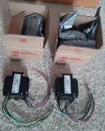
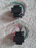


-
Locked
Built Elsinore MFC MK6 Crossovers..Upgraded.
SOLD
I had plans to build the Elsinore MK6 MFC speakers (See the mega thread here). Plans changed. I had an upgraded parts crossover set sourced by ScottG and built by MTG90. They are the easy button if you're thinking about building a set of the Elsinores. I can detail the parts list if someone is interested. Almost every part was upgraded IIRC (its been a few years). Over $700 invested 2 years ago so I'm sure it would be more to built today.
. Asking $OLD shipped.
Load more
Projects by fanatics, for fanatics
Get answers and advice for everyone wanting to learn the art of audio.
Join the Community
507,624
Members
7,880,747
Messages