Service (Maintenance, Troubleshooting) on PWM Class-D (Class-T) Power Amplifier Stages - which Papers, Documents and Books ?

Troubleshooting on PWM/Class-D Power Amplifier Stages - which Publications are released ?

concerning not digital amplifiers like tube and solid state single ended and push pull class A/AB there are a lot of publications available - e. g.:
https://sound-au.com/troubleshooting.htm
https://www.allaboutcircuits.com/worksheets/bjt-amplifier-troubleshooting/
https://www.google.de/books/edition...ier+Repair+service&pg=PA1&printsec=frontcover
https://www.google.de/books/edition..._Guitar_and_Amp_Mai/FCaskxpGLooC?hl=de&gbpv=0

Concerning Class-D resp. PWM power amplifier stages I just found only publications regarding the basic operation and special circuitry features, but not regarding service and maintenance/troubleshooting - go to this URL's:
https://www.soundandvision.com/content/bruno-putzeys-head-class-d
https://books.google.de/books?id=sF...=gbs_selected_pages&cad=2#v=onepage&q&f=false
https://ieeexplore.ieee.org/document/954289
https://www.allaboutcircuits.com/projects/how-to-build-a-class-d-power-amplifier/
https://www.semanticscholar.org/pap...g-Ge/e5adc785ac9fdfbd546e7bad725a6cb5fcadc341
https://www.semanticscholar.org/pap...-Wei/1b37a348f7a5418b7fe62394ce9bf28c22685b13
https://www.analog.com/en/analog-dialogue/articles/class-d-audio-amplifiers.html (go for an overview to last page)
https://forum.visaton.de/forum/mess...uben-ein-korrekturprogramm-würde-alles-regeln
https://web.archive.org/web/2020112...ion-bruno-putzeys-purifi-hypex-kii-mola-mola/
https://www.audiosciencereview.com/forum/index.php?threads/interview-with-bruno-putzey.14970/
https://www.diyaudio.com/community/...n-a-decent-book-on-class-d-amp-design.196068/ (closed thread)

what is the reason therefore ?
Maybe confidential details (B&O, Hypex and most other manufacturers always explain the same: ""No User Serviceable Parts Inside") ?

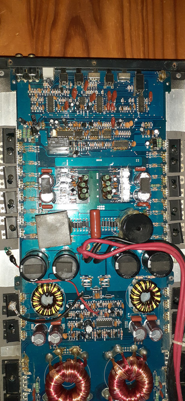
For this reason the complete class D main board resp. module is in general to replace on power amplifier devices in case if occur any failures/issues.

P.S.: why is this thread closed resp. inactive ?
https://www.diyaudio.com/community/...amplifier-books-overview-google-books.153311/

DC coupled long tail pair with CCS, need some guidance please

Hi guys,

I am trying to improve an amp I have here and using this nice chassis/amp as a learning platform. It's a combination of topologies I am vaguely familiar with but don't want to start smoking parts by just diving in. I have been reading about CCS in LTP, no problem by itself with AC coupling to the grids, but this amp has an SRPP (or maybe it's a CCS loaded triode) which is DC coupled to the 6SN7 grids. I have made all the required voltage/current measurements and put them on the schematic. I am planning on an LM334 for the CCS but am open to other suggestions. My main concern is the 93 volts on the tail of the cathodes and the voltage limit of 40 for the LM334. Could I put the LM334 on top of the cathode resistor, maybe drop it to 10K so the 334 has about 10V across it? I am also open to changing the input configuration to something else, maybe another LTP and AC couple it. The 2 input tubes are on a PCB so changing topologies would be a challenge, but not undoable.

Looking forward to learning more about this type of circuit.

Thanks for any help you may be able to offer.

Cheers

PS current in input stage 1.6mA, LTP ~3.5mA per leg

M99.jpg

Kind of Ironic and Kind of Sad

Coming up soon on March 5th 2023, the 60th anniversary of The tragic death of the Legendary singer Patsy Cline.
She'd be 90 years old today had she lived, passing away at 30 in that plane crash in Camden Tennesee.
What's kind of ironic is, her one popular love song, "I Fall To Pieces" struck me oddly.
Her remains were mostly intact at the crash site, except that half her face was ripped off, her body was jammed under a down tree (a result of the crash) and her one missing foot was found dangling up in a tree.
The investigators knew it was hers, it had painted toenails.
So... in a sad, tragic way, she finally did "fall to pieces".

I had the pleasure of meeting her husband Charlie, and her daughter Julie at a dedication ceremony in Winchester Va back in 2005.
Charlie is now up there with Patsy since then, and Julie is handling the Patsy Cline museum there.
RIP Patsy, you'll always have a special place in people's hearts.

patsy_framed.jpg

PCBs: JLH Class A amp; Elvee Denoiser (single and dual rail)

Hi

I do not think I will ever make JLH Class A amp. I have some other amp on my wish list..
The PCBs are from siliconray £12 + shipping (you need two for a stereo pair, the price is for the stereo set)

Also I have some surplus Elvee's diegomj1973 denoisers single (£3) and dual rail (£4) plus shipping.

Attachments

  • IMG_1258.jpg
    IMG_1258.jpg
    417.6 KB · Views: 238
  • IMG_1257.jpg
    IMG_1257.jpg
    599.3 KB · Views: 236
  • IMG_1256.jpg
    IMG_1256.jpg
    391.4 KB · Views: 223

Altec Model 14 2K crossover designed by Richard C.

I am ready to order parts for the above but am not sure of the DCR values for the inductors. They are not specified on the schematic. I plan to use quality air cores.
The internal wiring for the drivers is 20 gauge, rather thin I believe. These speakers are used at relatively low volume settings sometimes with my 8 wpc SET amp and sometimes with my Hegel 250 wpc ss amp.
I will use 10w wire-wound resistors because that's what is in my OEM crossover. I am considering upgrading the internal cabinet wiring to either 18 gauge or 16 gauge. My inclination would be to pick inductors with the same AWG. Of course that alters the DCR value which is why I'm asking for advice here.
Note: the OEM inductors are iron core and the wire leads look to be 20 gauge.
Opinions and suggestions please!
Many thanks, Fred

FS: filament transformer AAE Transformers, finest quality

FS:

hi all, selling for a friend:

1 power transformer 28VA for different 6,3V filaments, manufacturer: AAE Transformers ( NL)​

-EI Core, grain oriented core laminations and vacuum impregnated.

PRI: 0-230V-240V ,1x screenwinding acts as a shield ( SCH)
-SEC: 6,3V 0,75A, 6,3V 1,2A, 6,3V 2,4A

finest quality, unused and never mounted.

49€


pse ask for shipping costs ( depending your country)

Attachments

  • 1.JPG
    1.JPG
    412.8 KB · Views: 110
  • IMG-1546.JPG
    IMG-1546.JPG
    351.8 KB · Views: 107
  • IMG-1547.JPG
    IMG-1547.JPG
    421.2 KB · Views: 84
  • IMG-1548.JPG
    IMG-1548.JPG
    476.1 KB · Views: 93
  • IMG-1549.JPG
    IMG-1549.JPG
    514.7 KB · Views: 102

Orion HCCA 5000.1Dv1 Power Supply Switching

So i have 2 of these amps, Orion HCCA 5000.1D v1, each amp only had damaged FETs, 1st is repaired and running perfectly all new FETs, changed out all the FETs on 2nd but this amp’s Power Supply section is acting “weird” and not like my 1st. I couldn’t upload the 3 videos to here so here’s link to Imgur. My apologizes.

Login to view embedded media
3rd video shows following:
top wave chan-1: Rectifier switching
Bottom wave Chan-2: PS FET gate switching
Switching starts normally, but soon as the waves build to full the switching “degrades” into what is on video, if I remove rectifiers the Power Supply will build as in video but will stay a square wave/not degrade. My other amp does not do this, it switches correctly. But amp does reproduce input signal at speaker output terminals (when output is switching; see 2nd/3rd video)

Maybe the 2 problems are related???

1st & 2nd videos show the output switching problem possibly related to gain knob? Output section will not start switching most of the time unless gain is at/near half. I’m going to try a replacing with a 3rd gain knob, as 2nd is doing same as 1st. When amp boots with output switching proper it idles at 6.25a and reproduces input signal at subwoofer, when amp is below half or less gain output section does not start switching and will not reproduce input signal at subwoofer

As it is now the only time the amp will not work is when output section will not switch, which seems to be gain knob related, but about to try a 3rd potentiometer.

I’ve never seen a power supply switch like this and I’ve never seen a gain knob do this to output section. Really throwing me for a loop.

Humming WAD Phono Series II Clone Question

I scratch built a WAD Series II phono stage ages ago. I modified it with a ccs on top of the first stage and a ccs below the CF out. I really love it.

But when I turn it up, it does like to make some hum. Attached is a picture of of my iPhone showing hum at 47db when the volume is turn way up. This is very noticeable between tracks or during quiet passages, but hey I've lived with it for years. But mostly not noticeable over my wife's screams of "turn it down!"

Well, I tried something new. I unplugged the turntable leads and replaced them with RCA with 100k ohm resistor grounded as in the picture.

The hum dropped very noticeably. See the next picture at 35db.

Does this mean I'm getting noise in from my turntable?

I can't find any obviously wrong grounding practice in the preamp. (And both the phono and pre are in one box, the pre-amp stage is nice and quiet.)

Any comments would be most appreciated.

Thanks,
Dan
IMG_2461.JPG
IMG_2463.JPG
IMG_2462.JPG

Planar Horn/waveguide design (Help needed)

I've heard a number of good things about horn designs, like increasing low-frequency response on HF drivers, improvements in directivity, better efficiency, etc. But it seems to be difficult to find documentation on how to control these various parameters and how to design a waveguide with specific goals in mind.
I am planning on building a speaker with some planar drivers from parts express, but all of them seem to have a sloping FR; lower in lows, and higher in highs. Thus I am hoping waveguides would be the solution to make them flatter and easier to crossover.

I planned on just making horns using trial and error to determine some of the variables that can be used to tweak a driver's response, but there has to be someone out there who's already done that science.
Does anyone know of any design methodologies or readings to point me in the correct direction?

Modifying my Neve 8801 Channelstrip (for more Attack options on Compressor)

HI, its my first post, im a noob to the point that i am not even sure i chose the right subforum. i think the 8801 is a solid state channel strip so i hope thats fine.

I bought it used, and i love it.
but there is 1 thing i'd like to modify: you can chose 4 attack times, however for 2 of them you have to open up the unit and switch some jumpers around.
(as a sidenote im baffled that they did this in such a price range)

2023-02-25 20_36_58-2023-02-25 17_19_13-8801_User_Manual_Iss6.png ‎- Fotos.png

the Jumpers are marked in red.
So i want to switch these position without opening up the unit.
A friend who knows nothing about audio but a little bit about electronics & soldering told me i can do this easily with these 2 components:
2023-02-25 20_37_47-SCI R13-29B Kippschalter 250 V_AC 10 A 2 x Ein_Ein rastend 1 St. kaufen.png


The frontplate of the 8801 looks pretty filled up, so without looking inside the unit im pretty sure there is not enough room to somehow make this "pretty" and add it on the front.
Since its my only rack unit, and i dont even have a rack, i would be perfectly fine with having the switch hang out at the side of the panel or maybe drilling a tiny hole on top.
2023-02-25 17_34_52-Neve 8801 Channel Strip – Thomann Österreich.png


Im making this post in hopes that 1st of all if this is somehow a horrible idea, maybe u guys can let me know, and secondly, if it works,
there is a few questions that came to mind.

nr 1, could it be, that with jumper configurations, there is a possibility of getting 2 MORE attack times (6 total) ?
nr 2. furthermore, is there like a supereasy way to somehow add even more attack times?
dare i say a potentiometer that fluent from 0.5 ms (current lowest attack possible) up to something like 30, 50 ms ? (current max is 8ms)


im assuming the 2nd idea is way too complicated and not realistic, im just asking since it would be epic if possible.

thats it, any tips/thoughts are appreciated
thank you

Audio Pro Stereo One speaker question

I know my chances are less than hitting a state lottery jackpot, but....
I have a pair of those cutie boxes that came with that system, but not hte rest. The problem: tohose boxes work (properly) exclusively with the matching amplifier, since they are response corrected in the low frequencies (Ace Bass system, kind of current feedback system). Without the amp the sound is very thin, not much below 70 Hz (Qts: 0.22, Fs: 75 Hz)
I reworked the woofer (removed the extra magnet, plus softened the suspension) so now they can be used with other amps too. But the crossover now is not matching, and it is potted in an epoxy box, so I can't rework that part. The sound is very good even this way, the Focal Polyglass woofer is a rather decent piece so I'd like to improve on it anyway. Does anyone has any info regarding the crossover of those boxes?

Attachments

  • audio-pro-stereo-one-micro-anlagen-1846.jpg
    audio-pro-stereo-one-micro-anlagen-1846.jpg
    100.1 KB · Views: 639
  • basschassis250.jpg
    basschassis250.jpg
    12.8 KB · Views: 366

Help a NOOB in the middle of some desert in Africa

Hello good people,
Need some advice, insight, suggestions and criticism from you. I recently got onto the diy bandwagon after years of being a consumer. Two months ago I successfully built a tda 2030 amplifier 😂, and now I feel that i should join the bigger boys with a discrete AB amp.

The below is a design 'stolen' from some chinese manufacturer, it's based on c5200 A1943 outputs.
I've tested it using a 20-0-20v transformer and it was kinda working with some problems. I don't have an oscilloscope. Here in Kenya the price of an oscilloscope can feed two villages for a month. (I'm okay with that though)
So, I'm diving blindly into it with just a multimeter ,soldering iron and some poor speaker whose life is on the line.

kindly check out the attached schematics and help answer the following questions.

1. What's the best (maximum and safe) transformer voltage and amps to run it?
2. How many parallel outputs are recommend to get more power and handle 4ohm loads well? And what can be done on the drivers to make them handle more output transistors?
4. Are the biasing resistors values and diodes done well?
5. What are the improvements, corrections, that can be done to make it a better sounding yet powerful amplifier?

I'm very, veeeery new to electronics. Y'all's answers, advice and support is highly requested and appreciated

Best regards

Attachments

  • IMG_20221026_222319_291~3.jpg
    IMG_20221026_222319_291~3.jpg
    137.5 KB · Views: 303

How to build an inductor

I want to build an inductor to make a first-order low-pass filter.

rescutoffinductoravailableactualpowercurrent
41200.005305164775.00E-031.27E+0260012.24744871
21200.0026525823852.70E-031.18E+0260017.32050808

I basically have to build a 5mH and two 2.7mH inductors based on which amplifier I'm going to use, but I don't know how to determine:
  1. The wire length
  2. The wire size (because it depends on the RMS current and the wire length)
  3. Diameter and number of windings
  4. Which material should I use for the core
For the high-pass filter, it was easier, from the power and resistance of the speaker I determined the maximum voltage (~35V) hence I bought 50V capacitors, but the inductor is a bit more tricky because the current is now involved and I don't know which equations I should use. Even if I did study electronic engineering, I'm able to prove the formula to determine the auto inductance, unfortunately, I have zero ideas on how to build a real inductor🤣. I would also guess that those theoretical formulas wouldn't apply here and that for sure there's some sort of simulator that can do a better job than me.

6-10 inch subwoofer build

Hello everyone,
I am an undergraduate student, not related to audio. I am planning to build a sub with 2 passive radiators, I am on the look for recommendations on the subwoofer driver, as mentioned being a student, my budget for the driver is 120 dollars average. I currently have Boreas BR02's as my speakers which reach approx. 51Hz as low. I would like also recommendations, considering the driver recommended, in the box size (I don't want another bed-side table). Also considering the driver recommended, I would gladly take other ideas for ported or other, in the case it is thought to be better.
Thank you for reading.

LM3886: Troubleshooting Enlightened Audio Designs Amp

First, I'm pretty green when it comes to chip amps, so expert help appreciated.

The amp in question is a Enlightened Audio Designs PowerMaster 500. The company is defunct, and I've not been able to locate a schematic or really much of any info about this amp, other than that it's 5 channel and uses two LM3886's per channel.

Four channels work fine, but when an 8 ohm dummy load is connected to channel five (no input signal), the current being drawn from the line goes from 800mA to about 2.5A and hangs there. Here are the voltages I can read from one of the two LM3886's for the bad channel (need to get a better needle point probe to safely reach the back pins):

Pin 1: +42.9V
Pin 2:
Pin 3: -42.8V
Pin 4:
Pin 5: +43.1V
Pin 6:
Pin 7: 0V
Pin 8:
Pin 9: -42.7V
Pin 10: -0.344V
Pin 11: -11.7V

For folks smarter than me- How did this work out?

As some here may know, I've been doing measurements on acoustic guitar bodies. My preferred way is with pink noise as excitation, though I can and have done it with Swept Sine. I'm using a Dayton DAEX25FHE exciter, weighing in at about 3.5 oz. I simply rest the exciter output on the guitar's bridge/saddle and use a rubber band and clip to keep it from "walking". It doesnt take much amplitude to get a clear response spectrum; the amp I use (for the pink noise anyway) runs off a +5V USB port, with its volume setting nowhere near full.

I presented this in another forum, with spectrums before and after the application of a "Tornavoz"- guitar speak for a ducted port - invented in the late 17th century. In the spectrums, both the cavity / port and first mode of the top of the guitar resonance was evident. One astute reader challenged the validity, saying the exciter mass weighing down the top - as now part of the system - would change its resonant frequency appreciably.

Made sense to me.

Of course, the going from a plain hole to a ducted port only changes the air cavity resonance. Adding a weight to the bridge area wont change that. So the effect of the Tornavoz was valid frequency wise (it brought resonance down, as expected)

So I tried an experiment; one, where the 3.5 oz weight of the exciter was applied as a downward force; held by clip and band, the other, the guitar was held vertically as if played, with the exciter held by hand, pressed against the saddle / bridge by hand. So the exciter weight was hand held, versus guitar held.

No difference in top resonance, in fact it went slightly down being held by hand - the opposite of what one would think. How can this be?

Something to do with the compliance of the exciter at resonance makes its virtual weight go to zero - I just cant wrap my head around it. Any help with thinking this through would be appreciated! Thanks.

6L6 Voltage Regulator

Hello, I have a concern over the 6L6 voltage regulator used to stabilize the output tube screen grids shown in the attached schematic. Seems like the Vhk is very excessive and, I'm not sure of the extent I can go with heater elevation. The first thing I am considering is a separate 6.3 VAC transformer for the 6L6 (I don't have a 5VAC tap on the power transformer and it is my understanding that the 6L6 CF should be run off of a separate PT winding). Should I also do the heater elevation? Any other specific recommendations? Can't say how long or how hard it was run like this. I have not run the amp much as it needs to be refurbished, but it sounds pretty good considering. I have seen one other very similar amp that Mr. Evans built that did have a separate winding for the 6L6, but this one has all the tube heaters running off the same winding. Any advice is appreciated. Cheers
Screen Shot 2022-07-28 at 1.23.14 PM.jpeg

DMV (MD, VA, DC) USA Cabinet Builders?

Hi all, long time lurker first time poster!

After enjoying my s2000 MTMs for 4 years I am looking to build Troel Gravesen's CNO-Grande, but am having trouble sourcing a cabinet maker. I have chosen this route after difficulty sourcing quality grade plywood and also not having access to a shop this time around. I am looking for at least CNC services but also open to complete construction. I know this is not truly DIY, but I would very much appreciate any and all help 😀

thank you!

Inconsistent speed: JVC JL-B31

2023 - okay, I really want to go through turntable circuit of my JVC (actually Victor) JL-B31 and fix the speed problem. This is something I posted about on and off last year on another forum, but I seem to have stalled with responses there. I'm hoping that someone has the patience to tell me what to test, and in some cases exactly how, right down to "put the -ve probe on A and the +ve probe on B"...Yep; I'm afraid there are many parts of the circuit/schematic I don't properly understand. I can post photos of anything that might help to clarify things.

I have the service manual, and have spent a lot of time gazing at the schematic and the components on the boards, without much in the way of enlightenment occurring. I've done some measurements but it clearly hasn't been enough to identify the problem. A quick summary:

Powered on, the platter rotates very slowly at first, picks up speed over about half a minute, and drifts back and forth between too fast and too slow. Top panel variable resistors don't stabilize it.

The switches, power cap and rectifier diodes all seemed to check okay, though I replaced a power cap anyway. I do need to measure the TO3 transistor, and I'm unsure/nervous about what to do there: it should be 75V, measuring the collector (metal case) and...where does the other probe go?

The replaced power cap is C822, which I've circled on the schematic (along with X814, the TO3 transistor I will need to measure). The other caps in the power supply I left alone. In the end, out of a faint hope that it might make some difference, I replaced the electrolytics, as there are only about a dozen. But much as I expected, that's not where the problem is.

Any suggestions about what to look for start with this? The motor is clean and lubed and there are no obvious signs of issues originating there.

Attachments

  • JL-B31 schematic.png
    JL-B31 schematic.png
    688.6 KB · Views: 406

KABD-4100 amplifier noise floor

Hey everyone! First time posting in the amp forum!

I have a Dayton KABD-4100 and the thing just hisses, I don't know how to measure it exactly but its very evident and more than I have heard in the past from other amps. I have this powered by a Meanwell Power Supply and when I unplug the input and the control board it just hisses. I have it running on a PC right now and that itself induces additional noise but just sitting there wondering what its doing with its life it just hisses.

Any recommendations on how to effectively lower the hissing on this thing?

Mysterious "Toshiba" 2SK389 SOIC devices found on Ebay. Not LSK389, different pin-out.

I found some "Toshiba" 2SK389 SOIC packaged dual transistors on Ebay. They do NOT have the same pin-out as the Linear Systems LSK389.
They are marked K389BL OF
I soldered them onto some DIP adapters to test them. (I checked the adapters for correct pin translations)
The pin-out appears (and works) as:
pin2 S1 or D1
pin 3 gate 1
pin 4 D1 or S1

pin 5 S2 or D2
pin 6 gate 2
pin 7 D2 or S2

No apparent connections to pin 1 or pin 8.

The FETs trace on the curve tracer just like a 2SK170 and are well matched for gm. However the current offset ( Idss ? ) can be mis-matched by up to 25mV gate V.
(half a step division offset with 15 traces and 50 mV steps, so 25mV mis-match) One device did trace perfectly matched.
I would think that adjacent dies would be better matched on Idss. Could these be matched 2SK170 dies in an SOIC package?

Looks like these SOIC parts have surfaced before:
https://www.diyaudio.com/community/threads/help-2sk389-soic-packaged.100856/
but no resolution. No Toshiba SOIC 2SK389 apparently made.

Any way to tell which pin is Source versus Drain. They (and 2SK170) trace exactly the same way by swapping S and D around. Does it matter?

And a small detail: The SOIC to DIP adapters have a foil plane on the back side below the chip, and a big plated thru hole to a smaller foil plane just below the chip package.
I assume this is intended for some heatsinkng effect. To get good thermal contact with the chip package should this plate thru hole be solder filled or maybe just some glue fill to avoid over heating the chip. Since these surface mount things get wave soldered, it would seem that momentary solder heating should be tolerable.

I was planning to try out the 2SK389 for a Mimesis type board in place of the 2N5565 that Goldmund used. Also planning to try an Analog Devices MAT02. Those MAT02 devices DO match perfectly on the curve tracer. (TEK576) I even adjusted the beam focus to try and see any difference. Perfect match.

Basics

Greetings, I want to build a decent amplifier to drive my front main speakers. I have a multi channel 7.2 AVR that's adequate for the home theater speakers but I don't think it pushes my newest pair of speakers to anywhere near their potential and even then, it's an AVR! I was looking around online for an integrated amp for them but the cost for even mediocre quality, vintage or modern/new is just out of proportion so I have decided that I would like to take a shot at building one. All I need is a 2 channel analog stereo amplifier that I can feed with the pre-outs from the AVR and will drive a pair of speakers with the following specs; Frequency Response = 34hz to 21khz, Sensitivity = 98db, up to 150 watts RMS, 8ohms, dual 8" thermoformed crystalline polymer woofers and 1" linear travel suspension titanium diaphragm tweeter. R-800F
I have some things to possibly work with but I would greatly appreciate a list of the most basic components necessary to build a suitable amplifier for these speakers. It doesn't have to be anything fancy or even good looking, I only need it to provide decent amplification from the AVR pre-outs to the 2 speakers. I have some parts already such as a large transformer from an old Harman Kardon receiver and the base to the case it was in. I have some parts taken from different receivers and car audio mono amps and various other things around but I am not sure what will work with what or what else I will need or won't need out of what I have. So a basic list will be a good starting point for me I think and then I can go from there once I can gather what I need.

Pacific Microsonics oversampling (with and without HDCD)

The original pmd100 and pmd200 chips are complicated beasts! I've heard that the non-HDCD filter PMD designed was superior to others at the time (say, Philips or NPC)
Anyone know whether the oversampling filters found inside the OEM pmd100 and pmd200 chips are different from HDCD filter by itself?
That is, in rare devices like the Burr-Brown PCM1732 delta-sigma 96k dac chip, that feature HDCD filtering, is the non-HDCD interpolating filter (that PMD supposedly designed (for use with non-HDCDs) also being used?
When Microsoft software plays back HDCD, does it use the full oversampler?
Bottom line: I'm not interested in HDCD; but just how different companies approach interpolation for common Red Book digital.

JBL A6000GTI rebuild

Shout out to Dr Zeus for extending me the chance to own one of these, it’s a holy grail piece for sure even though it’s not totally complete. Good news: all the important bits are there, the board with the status LED’s is missing but I can probably make one since it’s just some lights on a PCB. Bad news: still need a lot of work- the chassis has corrosion, one of the large silver aluminum pieces that goes across the top is broken, and the middle part and plexiglass window is absent as well.

I will electronically restore this, and if all goes well I’ll see about having the missing stuff recast. But it’s gonna take time...

Attachments

  • FF47A70E-579E-421D-BF44-0E674CF7BF5D.jpg
    FF47A70E-579E-421D-BF44-0E674CF7BF5D.jpg
    649.2 KB · Views: 296

Guitar preamp output stage

Hi all. First time posting on this forum, I have gotten alot of help over at el34world but I am looking for any more advice where I might find it. I am almost done designing a standalone preamp based on ceriatone chupacabra 50 for my friend. I currently am using valvewizard universal effects loop circuit as the effects loop/output but I am told that this will have significant distortion and impedance issues. I need V3B to output line level to an unbalanced input of a power amp (Like peavey classic 50/50). I have been reading the cathode follower sections at valvewizard but I am really struggling with the theory. I have built a few JCM800s but designing tube stages from scratch is a skill I am trying to learn.

Does anyone perhaps have a circuit I can use for an effects loop and output driver for this application? I do not mind adding more tubes or stages. Any advice really on how I can go about calculating component values? I really appreciate ANY advice, please let me know if I did not post enough information.

Attachments

  • Schematic_Chupacabra preamp_fixed.png
    Schematic_Chupacabra preamp_fixed.png
    38.9 KB · Views: 204

Iancanada Digital and Well Tempered Master Clock (Andrea Mori)

Iancanada FIFO Q3 and Reclock Pi (Retail of the Q3 was $125 and ReclockPi is still $75) - used $125

Well Tempered Master Clock Driscoll 5.6448MHz ($250 new plus $80 for the crystal) - SOLD

Iancanada Oven Kit for the SC-Cut crystal listed above ($39 retail) - SOLD

Iancanada UcPure ($87 retail) - new $75

Eaton 3000F/3.0VDC SuperCaps (retail $80 each) - SOLD

All together or separate. If you buy it all, I'll pay shipping in the US.

IMG_0408.jpeg
IMG_0405.jpeg

MA speakers and an ACA

I'm retiring (for the second time) on May 12th. I'll have time on my hands to build more speakers and other equipment, so I'm kicking around the idea of building the ACA Redux. Would this be a good match for a MA A10-2, MA A7.3, MA CHP-70, MA CHR 70?As far as the CHP-70 and CHR-70, I have more than one pair, so I wouldn't mind putting two in an enclosure. Maybe a set of microTowers?
Thanks,
Mike

Suddenly takes forever to log on

This evening (2/24/2023) both my computers take forever to bring up the site.
Sometimes I can't even get on.... just shows a blank screen and no loading activity.
If I use the one computer (Win XP) which requires logging in each time, eventually I can bring up the site.
But on this the Win 10 computer, it takes forever. - the "scrolling" bar just keeps repeating.
I've checked my logon saved info, it seems ok.
other sites online are fine and load in a flash.
Any changes made recently?

Questions related to XH-M56

Hello everyone, this is my first post. I am novice wrt. amps however I am enthusiastic about music and building speakers and DIY in general, just that the electronics side of things is not my strong point, however I am willing to learn.

I have this board: TPA3116d2 XH-M568 (or a clone of it). It's in no way 2x100W, other websites list it as 2x50W, identical layout.
My plan is to use it for a sound generator in a car, so it will be driven only at 13.8-14.4V when the alternator is running. For now, I am only using one output channel(L) with a 4ohm speaker, the other is open. I also am feeding a mono signal, on the input channel (L) that has a speaker(L), the other input(R) is open as well. I do understand that it's not a good idea to leave the other output channel open and this may fry the board. For input I am using one of the 3 inputs ports, present on the board, yet this does not matter, the board is apparently meant to be used with switchable inputs, I have just one source anyway, so I've selected Input1. So far, so good, it has decent power, probably not more than 10-15W on the 4ohm speaker. The sound is coming from an ESP32. The amplifier board has a stabilized 5V output which is very handy to drive the ESP32 without an additional stepdown regulator.

I have a couple of questions:
1) Should I connect the other output channel to the same 4ohm speaker? Is this possible with this board? I know that TPA3116 can be pBTL-ed, but I do not know the layout of this board. If so, how should the wiring be done, speaker connected to both + outputs, ore one output to be grounded?
2) In order to have more output power, I would need higher voltage. Is it safe to use a step-up buck converter in an automotive environment? Everything is fused and proper cable awg is used and the boards and ESP32 will be enclosed in an aluminum case, so if there is magic smoke at least there is some protection to it.

I know I could swap to a mono amp, yet I like the 5V output for the reasons mentioned above and I might want to run at some point a second speaker. Thank you in advance.

PS: I can post a link to the board if I am allowed to. This board is present on all big commercial sites.

For Sale RMI-FC100

Good day, gentlemen
due to lack of time to realize this project i offer it for sale.
I bought it a few years ago from a fellow forum member who wrote the following:
I have 2 packages of the GB offerred by Rudi Ratlos in 2016. I received them in 2017 and only opened up to see what was sent. One set is with the shunt regulation pcbs and the other is with the LT3062, as I thought I would like both. I also purchased an extra set of RC-100 and shunt boards from Rudy in 2019, as he wanted to get rid of them.
I can guarantee that you will not pay more than what I paid in 2016-17.` Let me know if any interest.
i don't want to make a profit either and would like the price of 190€ plus shipping that i paid at the time.

See attached pictures. Best regards
1676465225033.jpg
o Sale
1676465225039.jpg
1676465255900.jpg
1676465255906.jpg

I2soverusb - popping noise at startup

I've recently assembled a USB DAC with JLSOUNDS I2soverusb board with an I2S implementation of an AD1865 DAC.

The sound is perfect but when the DAC is 'engaged' by the PC/USB device there is a loud thump.

I have checked a few tests now - MOODE, VOLUMIO and USB AUDIO PLAYER PRO.

I can confirm each time the popping noise only happens when the player is 're-set'. For example, if the USB AUDIO PLAYER PRO app is closed and then re-opened, and the connection to the DAC is refreshed, there is a large pop. Or if I restart Volumio or Moode, it will give the loud popping noise. This happens whether using AC power or on battery of the computer.

I don't have a USB isolation device to break the ground to test, but I don't think it relates to a grounding issue.

Would adding a mute circuit assist in this case, or is there another work-around (apart from leaving the PC and DAC on 24/7!)?

AP8064 Chip

Please forgive if this is a noob question.
So I picked up this blue tooth module. By team pie called the TDM157. It uses a AP8064 chip I will try and include the data sheet for this.

My issues. The chip seems to have many functions that have not been used by the guy who developed the PCB.
The other issue is that the response is not flat. I don't think this is a bad thing. But if I connect via blue tooth and send it a freq sweep. And I connect my scope to the output I see that the voltage change with freq.
How hard would it be for me to make a custom firmware. Where I can use all the special functions of the chip and maybe develop a custom eq.
Visited the site of the company who makes this chip. Did not see any SDK.
Lets assume this chip does not support a SDK for custom firmware what chip is there out there with the best SDK and support.

Attachments

FS: B1k NuTube board populated

Sell the populated tested and working b1k board kit. Will build a second One with different components hence i sell this with prp resistors +4 100 ohm zfoil resistors that you see in the picture.sell for 160 Eur shipped to Europe. Price only for the board populated. If interested can sell the alps Blue with Pete board as well

Attachments

  • IMG_20230210_144104.jpg
    IMG_20230210_144104.jpg
    442.8 KB · Views: 186
  • Like
Reactions: Bas Horneman

Transistor Amp Testing Problem Help

Building a 30 watt class A amplifier using the attached LTSpice schematic and pcb layout. I have the prototype board set up on the test bench with a GW Instek GPE3323 regulated power supply, an OWON HDS242S for the scope and signal, and an OWON XDM1041 bench multi-meter.

First I tested without the output transistors installed. Power supply set to +/- 32 volts DC. The ground reference for signal and power are connected floating to the common of the power supply. All voltages at every node match the simulation results of the LTSpice run. With a 2Vpp signal I adjusted the bias to correspond with the voltage gain shown in the LTSpice run. All input signal voltage changes from 0.5Vpp to 2.6Vpp (clipping) thereafter matched and followed the corresponding LTSpice runs for signal gain. So far so good.

Connecting the output transistors (heat sinked plus fan), I adjusted the bias to 1.3 amps and the board ran at idle without issue over two hours, maintaining the bias current exactly at 1.3 amps. However, when I went to do a signal test and attached the signal generator lead to the pcb input, the power supply tripped at the cutoff current I set at 1.5 amps. Setting the current limit to the 3 amp max, the power supply still tripped and ran at constant voltage (about 5 volts).

No matter what I touch to the input node -- probe, rca cable, even a piece of wire -- the current draw increases (seems like it's shorting out somewhere). I even hooked up an rca cable from a cd player. Same thing, tripping the power supply.

I tried installing a 100K resistor between the signal input and ground upstream of the capacitor and removing the input capacitors. I tried tying the ground from the power supply common to the earth ground. Nothing changed.

I built another type of transistor amplifier using the same power supply and it works just fine. Never had the above issue while testing that one.

Appreciate any suggestions,
thank you

thanksCapture001.PNGCLASS_A_Sziklak.jpg

Audio Precision: AP 2.24 Horizontal Scroll Menu Issue!

Hey All!

I recently completely reinstalled my AP 2.24 software and now I seem to be having a weird menu window scroll issue. After the install, the bottom of each of my tool windows has a horizontal side scroll that partial blocks some features from being used (Like Append or Single-Point on the Sweep Menu). I cannot manually resize any of the windows by clicking and dragging. I don't see anything related to this in the Utilities/Config or anywhere online. I'm sure it's probably something simple I'm overlooking, but can someone shed some light on this please. Thanks!

ap224 issue.jpg

Balanced to unbalanced converter

Hello everybody,
I'm now working on another power amplifier and I want it to have balanced inputs along with unbalanced ones. I did several balanced input preamps and amps with the "classic" one op-amp and three op-amps designs but I was looking for a higher performance solution (if there is one). After reading several articles and the chapters dedicated to this subject from D. Self's books, I decided to try and build the schematic below. From several sources on the net, this seems to be a very low noise solution. I do not need level control but I would implement a gain switch to be able to switch from high to low gain and I will add an unbalanced input as well (from the IN+ and GND connections).
If any of you have experience with these and maybe built something like this, I would like to hear your input. I'm open to other ideas as well. The only real downside I see on the schematic below, is that it uses 4x opamps per channel. For me, this is not a real concern as the LM4562 opamp that I use extensively is not that expensive and its performance is very good (ignore the LME49720 MPN from the schematic). From D. Self's book, there is a lower noise solution that uses 6x LM4562 but the noise difference from the schematic below is not that big (2dBu) and the one below is more tan enough for what I need.

1676829207291.png

SE trans + chokes

For sale a oair if SE trans with 2,5 Kohm primary and 8 and 16 ohm secondary pkus 2 chokes 2H and 150mA.the transformers were taken from some old Copland amplifier. Iv used this for about 2 years now in my 2a3 amps. Working perfectly. This are abot 10x10x8cm big and weight about 3kg each. Plese look at pictures. Price for all four parts would be 90 euro plus shipping. Payment by paypal for friends.

Attachments

  • IMG_20230223_092603.jpg
    IMG_20230223_092603.jpg
    508 KB · Views: 158
  • IMG_20230223_092613.jpg
    IMG_20230223_092613.jpg
    611.3 KB · Views: 160
  • IMG_20230223_092624.jpg
    IMG_20230223_092624.jpg
    543.8 KB · Views: 158

Replacing Chinese Condensors in Tube Amp

I have a SUBZERO 20R (BluesJR clone) and I recently started to take interest in "bettering it".
I just did a small lead dress for starters and it really helped get rid of a lot of noise!
I am now considering changing the cheap trashy condensors for some more suitable substitute.

Would this help give the tone some more sweetness and lower the noise even more?
I'm thinking of replacing all of the Black Changx but am not sure about the rest of the red ones...

Very greatful for any insight because im just getting into all this mod stuff 🙂)


Pictures:

20230223_214405.jpg20230223_221355.jpg20230223_221359.jpg20230224_130836.jpg

QUAD 303 Faulty Right Chan

Hi

I have a Quad 303 amplifier, the right channel first went silent, then started to roar. I switched it off immediately. I ran it for short periods with nothing connected to it to measure voltages etc. Not one transistor reads the same as the working chan. Point A reads near the supply voltage with no control from the relevant pot.
Reading on the internet, it tells you to short out the base of tr101 then tr 102 to test the circuits but I am a bit reluctant to do so in case I damage anything with the voltage being so far off. Not sure how this circuit works in respect of balancing Point A to half the supply rail.
On You Tube the guy called Old git used equvalent (or better) transistors, so I replaced all (recomended) Transistors apart from Tr 105 and Tr106 on the board. Have checked around for S/Cs but didn't find any.

Not sure on how to proceed apart from keeping replacing components. I have no workshop facilities and only a multimeter, soldering iron and some odd componemts.

12AX7/12AU7 Classic China Pre-Amplifier Build

12AX7+12AU7 Classic China Amplifier "Marantz 7" style circuit?

Recently a friend donated me some NOS 6189W tubes they are basically 12AU7 mil-type. I wanted a simple easy circuit to plug them into. I decided to buy one of these kit preamps from Aliexpress. This one is from DIYBox store but there are a few others that sell this kit and some say "Marantz 7" style.
classic-amp.jpg


Just wondering if anyone has experience with them and can suggest tuning and mods for it. It probably needs some tuning or adjustments to optimize the circuit for the 6189W so i'm all ears. The PCB quality is very good.

The kit is basically:
  • 115VAC 30VA 0-220 / 0-16V R-CORE Transformer
  • 12AX7+12AU7 Classic Circuit Tube Preamplifier Board
  • 12V and HV Regulator Board

image0.jpeg
image0(2).jpeg

Attachments

  • classic-amp.jpg
    classic-amp.jpg
    160.8 KB · Views: 744

Monacor SP-200X TQWT

Hi all guys, I'm reading a lot on this interesting site, and I'd like to understand from you how I can go about finding the right design to make a tqwt with this full range. Obviously then, if necessary, a tweeter or supertweeter will be implemented (suggestions are accepted). The whole thing will be driven by a single ended el84. For now I have seen two interesting simulations, but with somewhat different parameters. One from the abmade site and one from the mh-audio.nl site

How to proceed?

1tqwt.jpg


FROM MH-AUDIO.NL


4tqwt.jpg

3tqwt.jpg

CheapoModo: a very cheap PCB that optimizes transformer snubbers

SOLD OUT . . . . SOLD OUT . . . . SOLD OUT . . . . I HAVE NO MORE KITS TO SELL

I've got quite a few kits of all parts + two sided PCBs to sell, for rev.3 of CheapoModo. The design is discussed in some detail, in another thread. Here in "Vendor's Bazaar" I am offering the kits for sale.

A full bill of materials is attached, showing my costs. I am selling each kit ("free" shipping is included), for
Code:
USD 10.00  if pay by check     and ship to USA
USD 13.00  if pay by PayPal    and ship to USA
USD 21.00  if pay by USD check and ship outside USA
USD 24.00  if pay by PayPal    and ship outside USA
Please feel free to compare my costs (in the BOM) versus the prices above, to decide whether it's a good deal.

For those who wish to build CheapoModo Rev.3 themselves, I've included the CAD "Gerber files" that you can send to your favorite Chinese PCB fab, and get your own boards made. Then you can use the BOM to order parts yourself, from DigiKey or another supplier. PCB size is 35mm by 45mm. The Gerbers are in a zip archive attached to this post, named "cmodo_r3.zip". You can have them for free, I hereby place them in the Public Domain.

If you'd like to purchase a kit, please send me a Private Message indicating whether you'll pay by check (USD denominated checks drawn on USA banks only, please) or by PayPal. Then I'll send you my mailing address or my PayPal userId.

Rev.3 includes a new 33pF speedup capacitor, which slightly improves the risetime on the crucial FETGATE node. The waveform shows the textbook classic "Miller Effect" when the gate of a MOSFET is trying to rise, at the same time its drain is falling quickly. Schematic is below.

edit- US Postal Service just changed their fees and policies for shipping outside the USA. This increases shipping costs by $6.00 per CheapoModo kit, and I have adjusted the price list above to include these new, increased, postage fees. I apologize for the shocking and embarrassing high cost of shipping internationally.

_
SOLD OUT . . . . SOLD OUT . . . . SOLD OUT . . . . I HAVE NO MORE KITS TO SELL

Attachments

  • CheapoModo_rev3_schematic.png
    CheapoModo_rev3_schematic.png
    27.1 KB · Views: 2,265
  • PCB_photo.jpg
    PCB_photo.jpg
    453.4 KB · Views: 2,231
  • Bill_Of_Materials.zip
    Bill_Of_Materials.zip
    6.4 KB · Views: 547
  • FETGATE_risetime.png
    FETGATE_risetime.png
    23.2 KB · Views: 2,129
  • Begin.png
    Begin.png
    30.4 KB · Views: 2,010
  • Almost.png
    Almost.png
    27.8 KB · Views: 1,992
  • Done_Zeta_equals_1p00.png
    Done_Zeta_equals_1p00.png
    24.3 KB · Views: 837
  • DONT_DO_THIS.png
    DONT_DO_THIS.png
    24.2 KB · Views: 915
  • cmodo_r3.zip
    cmodo_r3.zip
    19.4 KB · Views: 417

How to seal between the mounting plate and waveguide?

How do you seal between the mounting plate and waveguide? PLA plastic.

I would like it to have it zero thickness but still be detatchable for driver removal. A very thin rubber/foam gasket or some paste sealant? What product if so? Or is it just to over-do it? Will it be air-tight enough if 4-8 bolts are used to screw it together? (4 are shown below). The waveguide will boxed and woofers will be atatched later on, so I don't want the waveguide to become leaky.

Mount plate assy 1.png


Mount plate assy 2.png


Mount plate assy 3.png


Thanks/
Petter

VituixCAD - How to align woofer/tweeter measurements via delay?

Hi,

I've taken woofer and tweeter measurements on different axises and imported them to VituixCAD. I also took a measurement with the woofer and tweeter in parallel, with the mic centered between them.

My question is how do I get the VituixCAD measurement / starting point to be close to / equal to the parallel measurement? I want to make sure the software's starting point agrees with reality in terms of Z axis of the drivers, alternatively by adding a delay to one of them. This will be for a digital crossover.

Thank you

edit: Here's the REW response of drivers in parallel (therefore perfectly aligned time wise from a physical install perspective - not from a "is this the correct Z depth alignment for perfect sound" perspective):

Tweeter and woofer par okt 6.png


How do I get VituixCAD to match the above so the starting point is the same? Is it just switching back and forth between REW and VituixCAD while changing the Z depth of the tweeter until it matches somewhat? Because I can't get a good result doing that...

VituixCAD start.png

Designing my own PA

There is a long story here which you can skip, but I am the TD for a non-profit theater. The space is a black box with modular seating and ultimately flexible design. My current audio is 4 Yamaha 12" and an old Peavey M7000 amp. Remember those big brown anchors? The array is a cluster in the middle of the room hanging on swivels so I can point them wherever the audience is. Two of the speakers have blown horns and one has a 12" driver that was replaced with a paper cone/paper surround thing that looks like it came out of a Magnavox Phono from 1973. The phasing as you walk around the room causes dizziness for anyone with a good ear.

The theater obviously operates on a tiny budget. I was quoted $28k for a new audio setup that would be great, but that's more grant money than we can solicit in 5 years. So I thought, "hey, I've built dozens of speakers from someone else's plans, I should learn how to design one myself."

So here I am. I have a small truckload of MDF and particle board, a soldering iron, and $2500 in the budget. I'm hoping to whip up 6-8 small active wedges (think kind of like some full range center-fills) that I can hang from the grid over the audience pointing down a bit. Kind of like speakers in a car headrest instead of in the doors. For each show configuration, I can hang and point them, then send to a digital snake and XLR to each one. Low frequencies can be handled by a Yorkville sub someone donated.

Something that I can build with Dayton drivers for fifty bucks, slap on a $35 plate amp, and make it happen... instead of $750 each like these passive VTC Inceptions

1676326008886.png


TL;DR.... Looking for some plans for a 5.25-6.5" bookshelf-sized speakers on steroids that I can slap a plate amp on and use as a PA in my theater until the grant fairy leaves me a big check.

The space in question: (wide angle shot) 50 x 60 black box.

1676327426689.png

Firstwatt F1 makes temporary static noise on power up

I have a Firstwatt F1 amplifier that I bought at an estate sale not too long ago. It has mostly sounded great on a pair of full range speakers, but there is an behavior that I've noticed repeatedly that may need some attention. When I first power-on the amp for a listening session, I hear scratchy static noise on only one channel which lasts for 20-30 seconds. The noise is similar to what you might hear with loose speaker wires. (It's not the speaker wires... I've triple checked for bad external connections.) It doesn't seem to happen again as long as the amp remains powered up. If I perform a quick power cycle after the amp has been on for a while (and warm) the noise does not reoccur. It appears that the amp needs to be off for some time before I can reproduce the issue. (Perhaps providing enough time for the heatsinks to cool down and/or capacitors to discharge...?)

Could this point to aging capacitors that need replacement? Would anyone have any suggestions for how to track down the source of this noise?

Tall Skinny Sealed Box problems?

Hi Folks,
I've got some Pluvia 7.2HDs that I need to make some surround sound satellites from.
I, unfortunately, have a very small footprint I can give these due to WAF.

My total volume I can fill is 210mm x 160mm x 790mm.

I tried to find a nice little TL that might work, but all the ones I have ready access to: TABAQ & plans on the Mark Audio website, all seem to be about 830mm tall.

On the MA website, there is a sealed stand mount that is a 15.23L total internal volume that has a perfectly adequate tuning for satellites, but I need to morph the dimensions to fit my footprint. So the crux of the matter:

If I take a 160 x 238 x 400mm internal sealed box and morph it to be 136 x 180 x 622mm (15.22L) will I likely run into issues with resonances and half wave formation?

I might be drastically overthinking this.

What tonearm for AT Art-9 MC

Hello
Some time ago, I was able to snatch a AT Art-9 MC, which is said to be very good…
I haven't mounted it yet, and I’m not even sure if I got a suitable tonearm for it…
Vynilengjne has a very good database and calculator for compabilities, but it seems this cartridge (with its 8.5 grm mass and acompliance of 18 x 10-6 cm) is a bit a special one…

Right now, I have the choice between a FR-24 mk2, SME 3009 improved or a RB300…

What tonearm would you recommend? (Model or by specs)?

TI TPA3255EVM delayed fault

I have a TPA3255 that I've been using perfectly well for almost 5 years now. A couple weeks ago I decided to upgrade the enclosure and the power supply. Now whenever I try to use the amp (I've tried with multiple power supplies, including the old one and a 3rd one), it plays fine for about 30 seconds at which point the fault light goes on, and about 5 seconds later the clip light comes on and then both lights immediately turn off for a second or two until the Fault light comes on and the cycle starts again. The 3.3v LED also flashes in time with the clip light. I've tested multiple different speakers, line in sources, and volumes, but invariably the board stops functioning after about 30sec of working perfectly.

I've done a thorough inspection of the board, including under the heat sink, and everything looks pristine. I'm currently at a loss for where to go next on troubleshooting/repairing the issue. If I need to replace any components I have the tools (including if I need to replace the TPA chip).

something that may (or may not) be related is that my minidsp 2x4hd that I've been using for the last 5 years also stopped working tonight. I had everything wired identically to how it was before. I'm less concerned with repairing that minidsp since I can easily source an ADAU1701 DSP for $25, but replacing the amp is a much pricier prospect.

Edit: some details I forgot to include: The amp is setup in 2 SE + 1 BTL mode for 2.1 output. The issue occurs on all 3 channels.

Reverse-engineering GK bass EQ 5-string switch

I read this interesting interview with Bob Gallien and he talking about the "5-string" switch on newer amps that alters the longstanding GK EQ tone stack to lower the roll-off frequency of the bass from 40-ish to 30-ish Hz.

Cliff Engel _ Interviews - Gallien-Krueger - Brave 2_14_2023 2_30_40 PM (2).jpg


Do any of you have any ideas how this might have been accomplished in changing a resistor/capacitor or two in the GK tone stack, found in the attached schematic? Would love to mod mine to this effect if I can. Does anyone know of an online tone stack calculator that I could punch this into ? The TSC online works for Fender / Marshall amps, but how about this type? Any feedback welcome.

GK_200RB Preamp.pdf - Adobe Acrobat Reader (64-bit) 2_14_2023 2_38_02 PM (2).jpg

Attachments

The tale of two subs - solid state Consumer puffery (rant and solution).

OK , I bought a larger XT 12" polk(35$). (below pix). Nice box and woofer, but what a joke of an amp !! I still have the second Harbringer AP12
along with Panasonic/Rubicon for caps and trannies. The Polk woofer is "almost" a Dayton HO !! Below .... 7CM voice coil and 20CM magnet !
I will continue this thread with the "decked out" Habringer and my own phase/filter/level. I DON'T like the ebay kits ... he he...


(original thread)
Oh , how the unclean public is now raked over the coals with utter solid state garbage.
My beloved POLK 10" sub failed after 2 years. (below 1) is the AMP. I laughed (and cursed)
when I saw IT (below 1). What a POS !!!~ 100W amp my ar$e !! No wonder it failed.
Design seems to be an op-amp driving a high beta to-220 EF2 , how nice of POLK to outsource
to cost cutting cheap manufacturers.


Rant # 2 - I bought a dayton sub 100 (10") for 20$ , which I knew was at least slightly defective.
It worked for 2 hours. (below 2) is it's amp. It is 2010 , at least they used TIP35/36 and REAL class
AB (simple complimentary IPS). This subs flaws were the "good cheers" 50VA trafo and leaky unknown
electolytics , "jacek"?? Why have a decent amp with a sub par power supply ??


Both subs have things in common.

- Bare minimum power supply with dubious capacitors.

- Using the amp plate as the heat sink and designing a integrated electronic
thermal shutdown into the control circuitry. I suppose it is easier to
use a few chips instead of a pound of aluminum for a proper heatsink.

- Ratings and use factoring are in the realm of "puffery". The units
can not handle normal use - let alone abuse !! They are definitly designed
to hit the local landfill in 2-3 years. AS IS most of what you buy these
days. I understand this , buy a sub every 3 years ... as you do your PC.


This is why I DIY. I found AMPS for 14$ on EBAY - Harbinger AP12's and 15's
have nice a "blameless" layout , simple/compact onboard amps.

(below 3) is what I got (link) Harbinger APS15 200W Power Amplifier PCB Board, NEW | eBay

Not a bad deal. I reverse engineered the Harbinger circuit.
The last two attachments are the amp and it's 20- 150hz response.

There are so many blown 10 -12" OEM subs out there , why not design
a simple blameless type circuit to be a drop-in replacement. The Harbinger
circuit , by the reviews of the other buyers of this (replacement) amp .... seems to last
20-25 years with road musicians .
I would prefer this to the "puffery" of the 3 year OEM SCAM!!!

An IRATE OS....

Attachments

  • AP-12.jpg
    AP-12.jpg
    112.9 KB · Views: 634
  • ap-12.asc
    ap-12.asc
    10.7 KB · Views: 86
  • KT-Cordell models.txt
    KT-Cordell models.txt
    58.2 KB · Views: 81
  • IMG_20230211_183421418.jpg
    IMG_20230211_183421418.jpg
    411.1 KB · Views: 165
  • IMG_20230113_234518493.jpg
    IMG_20230113_234518493.jpg
    403.8 KB · Views: 162

Rockford 1500bd (old design) PC-3417-D

This amp came to me missing many components.
U18, U21, U11, U13, RCA inputs, all switches and pots, and the protect led were all missing.
Someone also replaced all the out put FET's.
Someone also replaced all power supply FET's with FQP 85N06 with 10 ohm gates (not sure about this sub) and all rectifiers were replaced as well.

All power supply FET's test good and the power supply has good drive signal.
The amp is making regulated and rail voltage.
I replaced all missing components.
All output FET's and power supply FET's test OK.

The amp powers up but the protect LED does not light up on initial start then shut off, and U11 is getting extremely hot
The class D section is not turning on like its in protect but the protect LED is not lit.

Does U18 carrier signal latch to U21? I can't seem to figure out why the class D section is not turning on. Any suggestions?

Hello from The Netherlands

Hello everybody!

I'm Johan from the Netherlands. I have always been interested in electronics and Hifi equipment. I recently found (or actually rediscovered) this forum on the internet and figured it would be nice to finally join!

Although I work in the construction business, I've been repairing stuff since I was a little kid. I do occasionally have some hobby electronics projects or audio equipment restoration going on. Furthermore, I work as a volunteer in a local repair café as I love to keep ancient devices and equipment up and running and away from the waste bins and landfills. The stuff people bring in is just crazy! 😊.

Cheers!
Projects by fanatics, for fanatics
Get answers and advice for everyone wanting to learn the art of audio.
Join the Community
507,637
Members
7,881,832
Messages

Filter

Forum Statistics

Threads
405,933
Messages
7,881,832
Members
507,637
Latest member
noname203