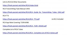
Help with power transformer wiring 115/230 etc. hope I didn't blow it up.

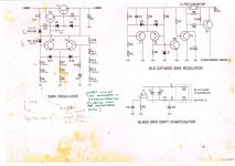
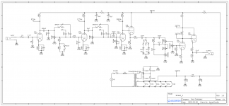
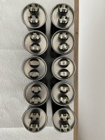
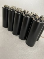
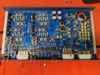
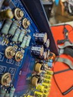
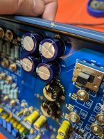
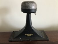
Well there's nothing like having a fuse blow instantly upon turn on to dampen your spirits. I have been working on this Opera M99 power amp for a week now tuning the feedback loop among other things and was getting ready to make the final adjustments today and when I turned it on the main fuse blew instantly. I have spent the afternoon working my way thru the problem and to me, it has to be the transformer, or the way I wired it 10 years ago when I replaced the original which had burned to the core (I got it this way) along with one of the output xfmrs. I managed to get the original xfmrs from Opera and went to my favorite Chinese restaurant to help me translate the wire colors on the label. It ran fine up until now, I pulled the cover off it, it's a nice heavy torroid and there is no indication of burn or failure, no shorts between windings and no shorted windings, as far as I can tell. So with all tubes out and HV and bias wires pulled from the rectifier board my 200W light bulb tester still comes on full brightness, I measure about 10VAC on the input to the xfmr and get about .5VAC on the heaters, 12V on the bias and about 20VAC on the HV windings.

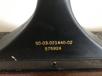
So I am now thinking I may have wired the primary incorrectly back in the day and something finally let go, I don't know I'm just taking a stab at it. Anyway, I have attached the label from the xfmr with a web based translation, as well as the original in case anyone here can translate it better. The measured R between primary windings seems normal, about 2.3-2.5 depending on voltage tap. There is one yellow wire, 2 reds, 2 blacks and one green on the primary side. One of the blacks is, or seems to be, directly connected to the yellow. Not sure if that is a short or is by design.

In your opinion, how should the primary windings be connected for 115VAC?

Thanks!

PS I am not sure "fuse" is the correct translation for the yellow wire, I got several interpretations each time I reloaded the image.

IMG_4233.jpeg copy.translated.jpg


power transformer label.JPG


IMG_4242.JPG

Question about power supply rectifiers heating

I have a Preamp based on the Doug Self Elektor "2012 preamp". I've built it according to his articles and it is functioning properly for a couple years with an occasional problem. I've had one of the diodes fail. On a separate occasion it blew the fuse but I detected no internal cause. It uses 4 MBR1045 diodes to form the full wave rectifier. AC is provided by a
Farnell (Multicomp) toroid transformer with dual 18 v secondaries, rated at 50VA. I have just noticed that the MBR1045 diodes are operating at about 80 C and wonder if that's too hot. The PSU uses LM317/LM337 to produce the +/-17V and a separate LM7815 for 15v to the relays. Heatsink on the ICs stay below 50 C. The MBR1045 diodes do not have a heatsink but I can probably find a way to add one if it's advisable.

I'm attaching a picture of the schematic and the board as built.

P3200020.JPG
P3200019.JPG
Your thoughts appreciated. Thanks.

Can anybody ID these tweeters?

Hi all, can anybody ID this tweeter which is one of two that came out of a pair of Wharfedale Diamond 2 speakers? I don't think it is the original tweeter which was a 20mm Audax plastic dome. It looks similar and is the same size but the back is different from images of originals that I have seen. The small print on the back at bottom reads K63TNM. If this is the part number I am not having any luck finding it on the internet. The red writing is the measured resistance across the terminals and they both measure about the same. The mounting disc is obviously cracking apart on both and will have to be replaced if I reuse these units. Any help greatly appreciated. Glenn

Attachments

  • 20230207_165639.jpg
    20230207_165639.jpg
    372.6 KB · Views: 233
  • 20230207_165736.jpg
    20230207_165736.jpg
    387.9 KB · Views: 199

Project "Artemis" - A complete stereo integrated amp with custom DAC

Hi!

Presenting a finished (they say developers job is never done...) project.
Since we all love videos and images:

Video:
Login to view embedded media
Hardware:


Android app:


You can check for more info here:
https://mladenbozic.com/project-artemis/

Desc:
Idea was to create something I will use, so making my own case by hand was out of the option (suck at it). So was buying some odd metal looking case I will later keep in some shed. Case should have high WAF factor! Always! 🙂 I've opted for a Pioneer A-10, it's a very low cost device which you can buy used for under 100$. And since this is a DIY project, you can do with it whatever you want.

Some shematics from different service manuals (Pioneer, Onkyo, Yamaha...) were used, power amp is similar to Hifisonix's KX-2/Pavel Macura's CFA amp but modified, all the PCBs were done from scrach and that was very hard to do as I had to adjust them all to the case at hand.

You can read much more on the link I've provided, here is the summary of what it can do:
  • Input selection based on relays
  • Custom developed DAC (PCM9211, WM8742) with power off function when not in use
  • Readout of frequency and bitrate from PCM9211 to mobile app
  • Digital filter selection for WM8742 in mobile app
  • Mute (relay based)
  • Speakers On/Off
  • Motorized volume control (4 channel ALPS pot) with ADC readings
  • Motorized tone control (6 channel ALPS pots) with ADC readings
  • Tone bypass (relay based)
  • Discrete bass boost based on Onkyo schematics (on/off relay based)
  • Discrete CFA pre-amplifier based on Marantz schematics
  • Discrete CFA power amplifier based on sources from the net (Hifisonix, Pavel Macura...) and own thinkering in LTspice
  • Bluetooth Low Energy connection to Android device for control and monitoring based on nRF52 module (Laird BL652-SA)
  • Custom developed Android application
  • Full IR remote control support
  • Standby circuitry
  • Dual power transformers connected in parallel after the rectifier for double current
  • Separate power circuitry for pre-amp, DAC, relays and digital circuitry
  • Protection circuitry for DC on outputs and power supply voltage asymmetry
  • Temperature monitoring based on Texas Instruments TMP100 IC and protection from overheating (work in progress)
  • LED PWM dimming ability
  • LED on volume knob (on/off option)

Today it's a fully working prototype, code is ok, some baby bugs I'm addressing but in overal it works. There are also links for code, which I provide for free, on the link above.

Comments and questions welcomed. 🙂

Rega Mira Integrated mk1-Gain Settings?

Hi all.
I was given a first generation "Rega Mira" integrated amp, in 'mostly' good working order (front and back face plates have some cracks/damage).
The owner mentioned thinking he had changed the "gain settings" of the amp, but couldn't remember how he did it, or what he had changed it to?
Would anyone know how to do this?
I looked inside the amp, and the only switches are for the "power amp/pre-amp" on/off dip switches.

Possible issue:
I confirmed the amp works but it sounded as though the right channel is a little quieter than the other.
While shifting the amp to better check the speaker inputs, I lifted the right front corner and heard that channel get a little louder/clearer, and then a loud POP.
I instantly let go of the amp, and it all returned to normal sound level and function.
No fuses blown, no smells, speaker is fine (Epos ES14).
Would anyone know what happened?
Did I discover a short or create one?

Many thanks!!!

Attachments

  • 401regamira40528.jpg
    401regamira40528.jpg
    9.8 KB · Views: 70

Purveyor; a dynamite small 3-way with concussive tendencies....

Now that InDIYana 2022 is post-op, I figured I post the details to this little marvel that impressed quite a few last weekend.
The name is appropriate, as Purveyor means to "provide what is required or necessary".

Goals:

  • Use a 0.23ft^3 knock down cab with a 3-way. This meant very careful driver selection, and a W-T/M orientation.
  • Make it easy to assemble for those with fewer tools. All but tweeters are surface mount.
  • Make it more affordable compared to most 3-way designs.
  • Yield great performance for the modest cost. All drivers have a magnetic shorting turn via a cap or ring.
  • Make a simplistic 3-way xover that is easy to assemble and would fit in the box with all of the drivers.
Drivers:

  • Peerless SLS 5" P830945; This is working in a 6 ltr net volume to produce F3/10 of 52/38. It also has higher sensitivity than ANY other 5.25" that can accomplish this bass extension feat. Being that, it has a lower Zmin above tuning at 150Hz of 2.3 ohms. This means the woofer lowpass coil has to be an air-core, and I was able to yield a Zmin of 2.6 ohms without speaker wires. This means it should be of a roughly stable 3 ohms by the amplifier sight, and a fairly stable 4 ohm load over all. It's a very minute area, and approaching 0 in terms of phase. Aluminum shorting ring, and long Xmax.
  • To accomplish this response in a small box such as this, there is no way you can use a port and tune low enough. It is just not possible. I was able to fit the SB Acoustics SB15SFCR-00 5x8" PR on the back of the cab. This involved using a midrange chamber of specific orientation to allow the PR to fit, albeit offset in one direction horizontally. 2x 0.5" x 1/8" thick washers and a stainless steel Allen-head M6x1 bolt were used to tune the PR to roughly 20Hz.
  • The Dayton Audio PC83-4 was used as the midrange. Being this is a 4 ohm driver, the xover landed at 650Hz to meld with the woofer to both keep impedance and xmax in check. Being the woofer is a 5.25", the off-axis response is really not impacted heavily. The tweeter and it landed at 5kHz, and the 83 has good enough off-axis response to make this just fine and keep the vocal range centered in the mid driver. The 83 also has a very benign breakup, likely due to its coated woven fiber cone, and it sounds fantastic. A decent xmax and copper cap keep it clean. 1 ltr sealed is all it needed, and this is a benefit here to give the woofer all the volume I could. (I used this midbass in the OSFA blue tooth speaker, and really liked its qualities. I also paired it with the following tweeter as a 2-way. I liked the results.)
  • The Dayton DSN25F-4 Designer Series 1" was chosen to finish off the top 2 octaves, 5k+. Paired with the PC83-4, the acoustic offset seems to be really similar, the CTC is small, and the frame is tiny. Sensitivity is 95dB, so it is heavily padded -13dB, and is loafing with a very easy living. On axis, there is a small rise at 12kHz of about 3dB, but most won't notice it. Just above the tweeter axis about 15* or +4", the rise disappears and the response is really smooth and flat. A copper cap keeps it clean. FF damps the Fs. Possible bonus? These tweeters have been known to be slightly leaky. If yes- then the midrange is in a slightly aperiodic box. If not- it does not impact the performance. Of note; I had a bad unit and PE replaced it. They are on back-order until July currently.
Place all into blender and pulse 3 times....

Xover points were 650/5k, not as pictured in the last sim-snap. I did not measure impedance and save it yet, so this should be close.
Xover board is 6" x 6.25". I ended up upgrading to the Cebo caps on the tweeters after the photo was taken. Much better, IMO.
Current prices:
P830945 = 36.98
PC83-4 = 12.98
DSN25F-4 = 18.98
SB15SFCR-00 = 35.70
Denovo 0.23ft^3 knock-down box = 26.98

Xovers as built: ~$115.20 each. I used the $4.00 75uF caps from ApexJr, and est a $1/resistor. The rest of the amounts are from Meniscus' website.

Total/cab comes to $247.14 including the cabinet, or $494.98; not bad for a compact 3-way! (My cost was $300 from discounts, salvaged upwound coils, used and free drivers, FWIW.) Most of the time, by the time you have xovers factored in with drivers on a 3-way, you're already in the $500+ category without even thinking about cabinets.

Attachments

  • IMG_4778.JPG
    IMG_4778.JPG
    579.6 KB · Views: 947
  • PurveryorSim2Final&VoicedXover.jpg
    PurveryorSim2Final&VoicedXover.jpg
    62 KB · Views: 823
  • PurveyorBox.jpg
    PurveyorBox.jpg
    207.3 KB · Views: 885
  • PurveyorCab.png
    PurveyorCab.png
    58.8 KB · Views: 792
  • Purveyor-RightHD+15degV_or4inches.jpg
    Purveyor-RightHD+15degV_or4inches.jpg
    134.2 KB · Views: 798
  • PurveyorSim2_AllMeasurements.jpg
    PurveyorSim2_AllMeasurements.jpg
    351.3 KB · Views: 667
  • PurveyorSim2_TweeterAxis_+15DegVRight_12thoctaveSmoothed.jpg
    PurveyorSim2_TweeterAxis_+15DegVRight_12thoctaveSmoothed.jpg
    67.8 KB · Views: 1,170
  • PurveyorSmallZoomFronts.jpg
    PurveyorSmallZoomFronts.jpg
    47.2 KB · Views: 1,245
  • SubtletySim1.jpg
    SubtletySim1.jpg
    246.8 KB · Views: 1,242

Technics SP10 stuff not mentioned yet

I haven't seen any mention of one of the SP-10's nicest features--the capability of lowering arm, sitting down in the sweet spot, and using the remote (wired) control to start the music. Mine's a MKII and I also have MKIIA. Anyone else doing that? Not sure if this feature is on MKIII or SP10R.
I made a video I can't find, but it's the bottom plate of my sp10 MKII hanging literally off a string. When struck with a knuckle, it rings like a bell. If anyone else removes theirs, listen for any changes in sound and report your findings. I'll see if I can redo the video Thanks.

--Al

Alpair 12 break-in question: 2mm?

Okay, tomorrow we build the Solstice cabinets and install the Alpair 12s. My next dumb question (hey, I gotta learn somehow!) concerns the break-in period. Mark suggests 2mm for 20 hours, and 4mm for 200 hours. Okay, I have no idea what that means! Is 2mm the volume of a normal conversation at a dinner table? Is 4mm the volume of your TV? Any help would be wonderful, because I really want these Solstice to shine!

Alnico-CA80 15 inch fullrange speaker

Never built a full-range speaker before. But I have to say that this sounds really good. Deep bass and particularly detailed highs for this speaker size. Very satisfied with the result!

Greetzzz Hondasnl

Attachments

  • PDFtoJPG.me-1 (1).jpg
    PDFtoJPG.me-1 (1).jpg
    838.4 KB · Views: 554
  • PDFtoJPG.me-2 (1).jpg
    PDFtoJPG.me-2 (1).jpg
    459.8 KB · Views: 524
  • DSC_0180.JPG
    DSC_0180.JPG
    508.3 KB · Views: 485
  • DSC_0182.jpg
    DSC_0182.jpg
    430.6 KB · Views: 450
  • DSC_0186.jpg
    DSC_0186.jpg
    308.6 KB · Views: 459
  • DSC_0192.jpg
    DSC_0192.jpg
    271.7 KB · Views: 329
  • DSC_0065.JPG
    DSC_0065.JPG
    466.4 KB · Views: 347
  • DSC_0229.JPG
    DSC_0229.JPG
    392.9 KB · Views: 348
  • DSC_0261.JPG
    DSC_0261.JPG
    495 KB · Views: 439
  • DSC_0231.JPG
    DSC_0231.JPG
    246.1 KB · Views: 438

What should i use as Ql, Qa and Qp values.

I recently build a subwoofer I used the parameters
Ql: 15
Qa: 30
Qp: 30

1677706775710.png


I should have gotten this frequenty response from a 6,5 inch dd506d2 in a double tuned bass reflex

But for my ears and my phone (using the app spectroid) it sounds more like this:
Screenshot_2023-03-01-22-44-10-353_org.intoorbit.spectrum.jpg

It has a huge peak around 20hz (at low volumes (such as the volume i took these measurements with) it makes port noise here so that could be a factor. The port has a diameter of 68mm so 2.677 inches with a length of 80 cm so 31.5 inches for a 6.5 inch driver.

When I use these parameters
Ql: 100
Qa: 100
Qp: 100
I get this response:
1677707591682.png

Which looks more like the actual response then the ones with "normal" Ql. Qa and Qp parameters. So now I don't know what parameters to use for my next build. Suggestions would be appreciated 🙂

Sb12pfc25-4 with pods(housing)

For sale a pair of wonderfull sb12pfcr25-4ohm drivers by sb acoustics, never used, just out of the box for the photoshooting.
The plan was to used as midrange at the pods, but the plans have changed.

Together I will ship a pair of 3d printed pods, very good and steady construction. They can be sanded and painted to any color you like, and can be used at car as midrange.

100 euros plus shipping
Pods can be sold separately at 50 euros for the pair. Also I can print pods for tweeters if you want to pair them.

Attachments

  • received_717459412918424.jpeg
    received_717459412918424.jpeg
    130.4 KB · Views: 98
  • received_682204823602258.jpeg
    received_682204823602258.jpeg
    169.4 KB · Views: 99
  • received_598779742254122.jpeg
    received_598779742254122.jpeg
    121 KB · Views: 94
  • received_2509585269182717.jpeg
    received_2509585269182717.jpeg
    138.7 KB · Views: 102
  • received_678097493861494.jpeg
    received_678097493861494.jpeg
    164.3 KB · Views: 97
  • received_1360839814656913.jpeg
    received_1360839814656913.jpeg
    138.6 KB · Views: 106
  • received_881314299724880.jpeg
    received_881314299724880.jpeg
    111.1 KB · Views: 99
  • received_5676117592435348.jpeg
    received_5676117592435348.jpeg
    129.2 KB · Views: 93
  • received_893810861746064.jpeg
    received_893810861746064.jpeg
    130.1 KB · Views: 93

Small 2-Way with Ciare 6.5" and 1,4"compression driver (Unibox sim)

Hi!

Im trying to build a small 2-way with high efficency. My plan is to use the Ciare HWG 160 for the Low/mid and a 1,4" driver for mid/high
Crossover freq at 1200.

This is my first simulation in Unibox so feel free to comment.

Attachments

  • grund.jpg
    grund.jpg
    138.5 KB · Views: 191
  • Exec.jpg
    Exec.jpg
    100.3 KB · Views: 170
  • freq.jpg
    freq.jpg
    102 KB · Views: 148
  • Port.jpg
    Port.jpg
    87.8 KB · Views: 141
  • step resp.jpg
    step resp.jpg
    107.2 KB · Views: 171

For Sale Hypex Nilai Kits or assembled amps (Monoblock and Stereo)

I have some spare Hypex Nilai Kits here (unused / new):


2 pc. of Hypex Nilai500DIY 1CH 500W Monoblock
(as seen here: https://www.diyclassd.com/product/nilai500diy-500w-mono-kit/184)

  • Kit: 980€ / each
  • assembled amp: 1080€ / each


1 pc. of Hypex Nilai500DIY 2CH 2x250W Stereo
(as seen here: https://www.diyclassd.com/product/nilai500diy-250w-stereo-kit/185)

  • Kit: 1480€
  • assembled amp: 1580€


I ship to addresses within the EU only.
(Shipping cost DHL w/ insurance comes on top)


Paypal fees are still added if you don't want to use 'payment to friends and family (“Sending to a friend”)'
bank transfer is also possible.


if you are interested you have to contact me via PM please

pictures will follow ...


SOLD ...

Why Does New Macbook Sound So Good?

apple-macbook-pro-1.jpg


Is anyone aware of how/why the speakers on the new Macbook Pro sound so good?

I normally listen to a set of Infinity ILS speakers in my office, connected to a pretty decent single ended solid state amplifier.

Tonight I was too lazy to get up and change tracks using my audio player, so I used my Macbook Pro instead. No additional speakers, no additional amplification, no external DAC. Just the speakers that come with the Mac.

And I was kinda astounded by how good they sound. In particular:

With natural recordings, there is honest-to-God soundstaging... from a laptop that's 36cm wide. With good recordings, the stage is significantly wider than the laptop itself. I'd estimate about 54-72cm wide.

I have a big project due tomorrow, so I don't have time to sift through Apple patents. I'm just going to make a few educated guesses:

1) I really enjoy 3D printing, but because of that, I've never invested a great deal of effort into making enclosures that are incredibly inert. The Macbooks are cut out of aluminum with a waterjet and they are STURDY. My Windows laptop feels like a toy by comparison. Is it possible that the solidity of the laptop's enclosure makes it sound dramatically better?

2) Apple is using force canceling midbasses in the Macbook, a la Kef

3) The soundstage is so surprisingly wide, I wonder if there's some kind of DSP processing going on, a la Opsodis or Ambiophonics?

4) I can't stand the Mac keyboard, so I keep the laptop quite far away, about three feet from my ears. (So I have room for a nice keyboard in front of the laptop.) So the sheer distance is probably improving soundstaging.

Anyways, if you have one of the new 16" Macbook M1 Pros, put some music on and let me know what you think. I'm not going to pretend that this can get loud, but if you're listening at a polite level at your desk, it's surprisingly good.

Citation II monoblock noise

I have a HK Citation II that has been converted to monoblocks. Over a period of time, one channel starts popping, like a plate pop, after the unit warms up. We switched tubes, replaced resistors that were getting hot to no avail. Any help would be appreciated.
There are photos of both here:
https://www.usaudiomart.com/details...kardan-citation-ii-mono-blocks-sell-or-trade/

Balanced to unbalanced solution

Hello,

I need a solution to go from a balanced DAC to unbalanced (RCA) inputs on one of my amplifiers and for subwoofer input.

I'm aware of 3 options
  1. Cable based - lifting or ground shields / pins as appropriate
  2. Transformer based - passive solution
  3. OPamp based - active solution

My searches aren't really finding some good "off the shelf" solutions. Bad terms, or something not really used / recommended. I don't know.

In anycase, I've found this, but being aliexpress - I don't know quality of the opamps in question and whether they are even genuine.
https://www.aliexpress.com/item/1005003718000938.html

Claimed to use a TI I believe INA137PA. Again.. whether genuine or not and whether this device is any good for the task.

powered by a suitable 15v AC supply.

If the above is suitable - dumb question. Can a single AC supply be wired to multiple boards? I assume if the current demands are less than the supply is capable of, no problem?

Thanks,
David.

6L6 Power Amplifier - A grandmasters unfinished dream

6L6 Power Amplifier - A grandmasters unfinished dream

I have been approached by the son of a local electronics engineer who passed away last year. He was still working on his ultimate valve power amplifier system.

All the parts and schematics were collected and I am now trying to make sense of it all. It is a difficult task to take on since the man who designed it is not available anymore for any comments.

The amplifier is quite elaborate. 100 watt per channel, servo bias control, overload protection as well as grid drift compensation and cathode windings in the output transformer.

In the notes the man stated that he battled with the overload that reset itself after a short while - he wanted it to stay latched when it tripped. Also, there is a spike pulse on the 500 vdc regulator.

If any member here is keen to cast an eye on the schematics, I would be very grateful.

Attachments

  • 20230114115144362_0001.jpg
    20230114115144362_0001.jpg
    309.7 KB · Views: 561
  • 20230114115316388_0001.jpg
    20230114115316388_0001.jpg
    331.6 KB · Views: 561
  • 20230114115356915_0001.jpg
    20230114115356915_0001.jpg
    181.6 KB · Views: 571

guitar preamp simulation

Hi all, I am trying to finalize my schematic for a standalone guitar preamp based off ceriaton chupacabra. I have implemented the output cathode follower from a soldano X88R and I can't seem to get it to look right in the simulation.
I need the output to be line level (1Vrms) and I do not know what values I should be using for the B+ drop resistors (R1, R2, R3 in the schematic, R11, R30, R32 in the sim) as just messing around with them I cannot get the dc voltages to match what the voltages should be (per ceriatones voltage chart and what I have found in a thread discussing an x88r clone for the output stage)

If anyone could give me some help figuring out where to go from here I would greatly appreciate it.

Attachments

  • Schematic_Chupacabra preamp_2023-02-25.png
    Schematic_Chupacabra preamp_2023-02-25.png
    35.2 KB · Views: 158
  • hamburger.asc
    hamburger.asc
    9.5 KB · Views: 87
  • Screenshot (33).png
    Screenshot (33).png
    31.9 KB · Views: 154

Down4sound JP23 Schematic

On my bench is a Down4sound JP23 amplifier. It uses 3205’s in the power supply circuit, and 640N’s in the output circuit. It came in with some swollen capacitors, short power supply fets, and short output fets.

I’ve removed all the fets including the rectifiers. I’ve disabled the protection circuit and when I power it up without any fets, I get proper drive on all the gate pads in the power supply.

The problem I’m getting, is when I fit the amp with two fets per side, the fets are heating up. The drive looks ok on the gate, but the drain looks like it’s not being pulled all the way down.

There are no rectifiers in the circuit so what could be pulling enough current to make these babies hot? Also, does anyone have a schematic for it or an equivalent?

Thanks!
9D94CE62-88E7-47D6-996A-D9D7AE6B9A74.jpeg

CDM 4/19 Standard / Composite Compatibility?

Great place here, have not posted for ages but I've had lots of useful info as I'm getting into CD players.

The Marantz CD65 II SE is said to use the 4/19 composite mechanism (metal and plastic I believe), whereas the CD65 II (and many others) use the standard 4/19, plastic only.
Can these be swapped? If I get a SE model I'd like to be able to fit the more common standard plastic one if necessary, even if there is a slight drop in performance.

I have searched but can't find the answer; it may be a silly question but better to ask!

I am considering having a CD65 II SE modded and converted to NOS, then I'd lampizate it myself.

FS 10x ASC X386S capacitors black coloured 30µF / 400VAC/800VDC

FS for a friend:
10x ASC X386S capacitors black coloured 30µF / 400VAC/800VDC from Vinylsavor

all caps are unused and located in germany.

blow out sale 250€ for all 10 together . Pse ask for dhl shipping costs.

Attachments

  • IMG-1864.JPG
    IMG-1864.JPG
    459.8 KB · Views: 144
  • IMG-1865.JPG
    IMG-1865.JPG
    453.7 KB · Views: 151
  • IMG-1866.JPG
    IMG-1866.JPG
    506.6 KB · Views: 124
  • IMG-1867.JPG
    IMG-1867.JPG
    388.9 KB · Views: 131

Mission 778 power amp adjustment

Hi. I have an early 80s mission 778 integrated amp (pre-Cyrus One, mosfet output devices) which I have just repaired (vol control needed replacement). It's sounding rather good but it does run hot, even at low volume levels. I've no idea if this is normal.

The power amp circuit diagram is here - Mission 778 - Manual - Stereo Integrated Amplifier - HiFi Engine - page 2 of the "schematic" link.

And you can see there is a trim pot in each output channel, with voltage measurements given. Looks like these measurements are close but not identical for the + and - rails. I've not yet measured the channels of my amp, but in general should I be looking for the + and - measurement points shown (marked as 14.6v and 15v respectively on the diagram) to be the same?

If these measurements are not the same / near the values given, would this cause the amp to run hot, or is it nothing to do with that?

I'm fairly handy with a multimeter and soldering iron but I do not understand the finer points of MOSFET power amp design.

The output devices are fairly substantial T03 can devices fitted to a substantial finned heatsink. However after nearly 40 years I guess the thermal grease may be past its best?

Any advice appreciated.

Paul

Eton seems to be on the rocks, at least in North America

I visited www.solen.ca (Solen Montréal) website and I was hit with an "EVERYTHING MUST GO!" style banner, closeout pricing on all their Eton inventory.

Well, that's a shame--the more I hear the 5-312 Kevlar woofer-mid, the more I love it.

The Jungle Telegraph tells me that Madisound is dropping the line also, just perhaps with less fanfare.

Too bad.

john

Need recommendations on 1000uF 50VDC power caps <18mm tall for Soundstream Refrence 604

Hi all, new to the forum here. I am currently getting everything together/setup for installing a sound system in my old W123 Mercedes. I have a McIntosh MX406 HU, Soundstream Reference 604 Amp, and have a variety some old-school MB Quart premium speakers and crossovers incoming. I'm am refurbing everything before install.

Everything works on the Soundstream amp and it is clean inside (except for some discolration around the power chokes, but amp has been bench-tested). However, I am going to be re-capping it. I am having trouble finding replacement caps for the 4 big power caps that are rated at 1000uF and 50VDC. They are currently Nichicon VS-series (cannot find datasheet regarding these anywhere) and 20mm diameter x 15mm height. The big issue is the height! I can go a little taller than 15mm, but not much as there is no clearance beyond ~19mm. I cannot find any caps to fit these specs - all seem to be 20mm, 25mm, or 31.5mm tall which will be too tall. Does anyone know of a current cap that will fit these physical restraints for this purpose?

Thanks,
Allen

Attachments

  • PXL_20230223_022017763.jpg
    PXL_20230223_022017763.jpg
    667 KB · Views: 98
  • PXL_20230222_231152900.jpg
    PXL_20230222_231152900.jpg
    366.3 KB · Views: 99
  • PXL_20230228_010058672.jpg
    PXL_20230228_010058672.jpg
    398.6 KB · Views: 105

Cathode Feedback from Output Transformer Secondary Free for All

A thread devoted to the subject of CFB from OPT secondary side to output tube cathode.

I've moved the 811 SE amp over here for a start. Looking at the operating conditions the claim of 24W audio doesn't make sense.
Running 80 mA plate current from a 600V supply looks like 48W plate dissipation, about the limit given in the RCA TT4 Transmitting Tube Manual.
In Class A Triode efficiency max's out at 25W. That can be pushed somewhat farther but it is no longer Class A & distortion increases.

I tried plotting the Tango 5K loadline on a poorly copied image of 811 plate curves. Trying to flatten the RCA TT4 manual
to stuff into the scanner was a real problem, By using an olde formula found in many RCA tube manuals the loadline never got more than 12W.

I've included some very interesting links, some for the fans of transmitting toobz.

No Sim to measure DF yet, I'll stuff that into the thread later. Time to get outta here for a few hours, 👍

Attachments

  • 811A 24W SE Amplifier.jpg
    811A 24W SE Amplifier.jpg
    85.3 KB · Views: 900
  • 811A SE Amplifier PS.jpg
    811A SE Amplifier PS.jpg
    106.7 KB · Views: 636
  • 811A Plate Curves.jpg
    811A Plate Curves.jpg
    57.1 KB · Views: 428
  • Tango SE OPTs.jpg
    Tango SE OPTs.jpg
    72.6 KB · Views: 331
  • 811A Plate Curves & Power Limits A w Captions.jpg
    811A Plate Curves & Power Limits A w Captions.jpg
    22.4 KB · Views: 310
  • Links to RCA & Other Documents.jpg
    Links to RCA & Other Documents.jpg
    93.6 KB · Views: 545

For Sale New pair of Dayton RS225-8 and pair of Wavecor SW182BD01

Have a new pair of Dayton RS225-8 woofers $100pr plus shipping and new unused pair of Wavecor SW182BD01 small subs $150pr plus shipping. Both from projects that went in another direction. Both pairs still in original packaging and never used.

Attachments

  • dayton RS225-8.jpg
    dayton RS225-8.jpg
    89.2 KB · Views: 120
  • Wavecor SW182BD01.jpg
    Wavecor SW182BD01.jpg
    98.2 KB · Views: 130

KEF 104/2 reference - which ferro fluid?

Hi there,

besides the donut repair and some cosmetic workover (I'll plan to put some new walnut veneer on the cabinets), I want to replace the ferro fluid in the drivers. Now I read somewhere, that there are different ferro fluids available and each one might have a different impact. I have no clue about regarding that topic. Does anybody know what KEF used in the 104/2 and what I have to look for? Or do you guys think it doesn't matter and any ferro fluid will do?

Thanks
Boris

For Sale Antek AS-3218 300VA transformer + DIYAudio PSU board with Pana 22000uF caps

Antek Transformer and mounting kit + PSU for sale in the UK.

18V duel secondary leads have spade crimps on them, but otherwise transformer as new/ unmarked.

PSU board is populated with 4 large 22000uF, 50V panasonic caps, snubbers, posts, bleed resistors etc. Will also be supplied with 2 rectifier bridges.

Everything you need to build a First Watt +/-24V supply

£150+£10 postage in the UK

Thanks

Help me cook something up with 6S4S

Hi,

It seems I've been spending too much time on Ebay again, this time resulting in a quad of NOS 6S4S (soviet 6B4G equivalents) being on their way from Hungary.
As I have a slight case of PTSD after chasing hum in a 6B4G SET that I built twenty years I also ordered a pair of Coleman filament regulators.
My speakers have a near zero tolerance for hum...:
anl1.jpg

At first I reckoned my James JS-6112 HS OPTs (2,5k/3,5k:4/8R) would be a perfect match, then I got some indications that people seem to prefer a less steep loadline for the 6S4S.
That made me think of my old, unused LL1688s that I bought fifteen years ago for a transmitter tube amp project that never happened. According to the datasheet they can be connected as 5K:8R. Absurdly oversized, but wouldn't it be fun...?:

opts.jpg

It also seems that 6S4S can appreciate a bit of grid flogging, a.k.a. class A2 operation. This rules out the basic "input triode RC-coupled to output triode"-topology, leaving us with either some form of direct coupled follower or interstage transformer coupling as the only realistic options. I succesfully used high gm cathode followers to push some triode wired 807s into deep class A2 in a recent project, so it would be interesting to try interstage transformers this time. Some digging in my storage room rewarded me with this:

its.jpg

The LL1660 seems to have a bit of a shady reputation as an interstage transformer (but supposedly excellent as line output wired as 4,5:1) and the DCR is a bit on the high side for pushing any real grid current. Those LL1671s seem like a better choice here, although the 50mA airgaps calls for some rather meaty driver tubes.
Speaking of driver tubes, here's a short list of some candidates from the shelf behind me:

  • Sylvania 6AV5GA, the (in)famous 6B4G replacement that has been discussed thoroughly on this forum.
  • 4P1L. Adding another DH tube would complicate things quite a bit, and my gut feeling tells me they would prefer ITs with a bit more primary inductance (21H estimated)
  • 12B4A. Also a bit of a stretch considering the 50mA airgaps
  • 6EW7. Dual triode with one low mu/low Rp section, though I only have 3 and they are rare in Europe.
  • 6S19P. Got plenty, not sure how good they are as drivers.
  • 807. Not the most linear as triodes, but at least they look quite cool.
  • PL36 (25E5). Nice triode curves, slightly inconvenient 25V heaters.

As for input tubes, I have a small batch of 2C22 / 7193s that would probably do just fine here, being ~equivalent to 1/2 6SN7 with dual top caps.

My mind gravitates towards something like 2C22 - LL1660 - 6AV5 - LL1671 - 6S4S - LL1688.
Surely an ambitious idea and I would very much like to hear any opinions you might have have about it.

Best regards
Daniel

CTS 450 and 450S series pots needed, uncommon values

Does anybody have a source for CTS series 450 and 450S pots in uncommon values? I can get 250K and 500K, no problem, but I also need 180K, 1 meg, 100K, and 10K.
Ideally these would be 450S pots with built-in switches but if I can just get the 450 type I can do element swaps.

Yes, I could go to the newer CTS push-pulls with 6 solder terminals but if I do that then I'll have to rebuild the whole front panel wiring/grounding scheme and I'm looking to keep it as original as possible.

Setting up a Chromecast query

We need to set up again as the device isn't working well.
It has been pointed up that plugging the Chromecast device directly into the HT amplifier isn't the best idea due to the large number of audio, power and HT cables behind the cabinet and all of the very solid speaker boxes between the device and the Wi-Fi extender.
I just went out and bought a new 5M long HDMI cable and a double female joiner so I could move the dongle somewhere better.
So two questions; is the shortest the distance between the dongle and the extender really important if that distance is less than 4 metres and does the plane of the device matter?
I can figure out a way to fix it to a wall in a vertical orientation or just leave if horizontal on to of the CD and vinyl cupboard, close to the ceiling and with a clear LOS to the extender. So does orientation matter?

Can a small hole function like an aperiodic membrane?

Hey, folks...

I created very small mid-bass enclosures (for 6.5" woofers) in the bottom of my doors (0.07 ft^3). I know that's tiny, but (without getting into ALL the parameters of the system), I didn't need them to play lower than ~120 Hz, so I thought I could "get away with it."

The overall system sounds good, but I couldn't help but wonder whether giving those drivers a little extra "breathing room" might make it sound even better. So, I entertained the idea of making these small, cylindrical enclosures into aperiodic membranes by adding a "vent" to the back of each. There are some good write-ups online for constructing them, so I felt confident.

Before diving in and cutting up what I had, I created a "test enclosure" --a small box with the same volume as the enclosures in my doors. Before creating my first vent, I drilled a small hole (0.5" diameter) into the center of the box, directly center behind the woofer's magnet (just to see what might happen). I stuffed the enclosure full of polyfil and remounted the 6.5" woofer.

TL;DR:

I pressed on the cone, and it (predictably) allowed more excursion, with a gentle puff of air released from the hole. Curious as to how it would sound, I hooked it up and my objective seemed to have been achieved! It boosted output between 90-110 Hz by at least 6dB. And I didn't do any REW measurements (yet), but it sounded nice with music, too! And there was no chuffing from the hole (that was my initial concern).

On a first blush, this "small hole solution" seems to WORK... but am I missing something??

Is it because the enclosure is so small? Because of the frequency band (~90-300 Hz)? Because of the polyfil? Did I just get lucky??

I couldn't find any record anywhere of anyone having done this successfully, so I full expect that I AM missing something!

If anyone has any thoughts about this (specifically, whether the hole can be used in lieu of an aperiodic membrane in certain cases--rather than WHY I would do that instead of a million other 'better' things), I would love to hear from you!

Thanks!!
  • Like
Reactions: NeonDriver

Tap-in tempo (metronome)

I have adjusted the settings to simulate a metronome (drums only, change drums to click, set Click 1 and Click 2 to the same thing). At this point, I think I have two requests

1) It would be nice if the tap-in tempo function performed a running average of the taps to calculate the average tempo that was being tapped. It occasionally seems that it might be

doing this, but then just one faster tap will make the tempo jump dramatically.

2) It'd also be nice to be able to turn off the extra beats. By setting the time signature to 2/4 I can eliminate half, and by setting the click to 2 and 4 I can reduce them again although

they would happen at the wrong time. t would be nice to see a 1 & 3 option, or a 1-only option so we could get a single metronome click without screwing around with the chart.

Maybe I'm missing something? Maybe setting
Click 2 to None (which isn't available of course) would do this?

Pioneer CD skips forward/backward

Hi guys. I have a problem with the Pioneer CD player - multi changer side.
Skips forward / backward. I don't find any regularity when and why it does it, every time it's different.
Usually this is solved by lubricating the axis on which the lens moves, but in this case it is something else. I can't find trimmers to adjust focus/tracking gain
which could solve the problem. Optics are KSS-213C model W739
I made a video of the problem: Login to view embedded media Login to view embedded media Login to view embedded media Login to view embedded media Your's advices will be appreciated.
Regards!

Ideas for a diy attempt of a transient shaper (maybe combined with a compressor) as a rack unit ?

Hey to the forum !

I already went with it to groupdiy but thought the more space covered the better !

Does anyone of you know of a diy project to build a transient shaper ?
Maybe combined with a compressor (but not necessarily so) like the : https://www.tegeler.com/Magnetismus2/Index

There are a few interesting plugins too that could be a inspiration like the : https://www.bozdigitallabs.com/product/transgressor-2/ for example

Maybe there are pcbs around for already existing projects or anybody has a brilliant idea here how it could be made OR already thought about it but it never got reality
Lets see that !

All the best !

Some acoustic guitar body measurements

I bought this acoustic guitar on line, used, boy did it sure look nice! Unboxed it, tuned it up and first chord, Uggh. Bright and boxy, just what I dont want to hear. I was wondering why this might be...

So I get out my Pink noise test kit and instead of driving a speaker, I drive a Dayton DAEX25FHE-4 exciter with the little USB powered class D amplifier setup to only play a Pink Noise file on an SD card.

I put a thin gasket foam pad on the exciter VC, to cover the monstrously sticky adhesive that comes with it. Turning the amp volume down to keep the exciter from jumping all over the guitar, I placed it just setting right on the bridge. Clearly driving pink noise into the same spot where the strings actuate the guitar's membrane-o-phone, or "top".

I have a couple older Yamaha G-XX models, which are reputed and to my ears, have a good sound.

Yamaha G60A NS.jpg


It's pretty easy to see the builder's effort to hit a comb at 110, 200, 440 or the "A" note, though it may be off some.

Yamaha G130 SM.jpg


Pretty similar response for the G130, albeit being strung to concert tuning. Apparently all that tension doesnt effect the resonances.

Now let's look at that guitar I didnt particularly care for;

Alvarez RC20SC.jpg


It's clear that the body resonances are shifted higher in the construction of this model. One wouldnt think so by looking at it - it's got a big, deep body. I've read on line that there's pretty much nothing one can do, without risk to the guitar's mechanical integrity, to change this. Better off to sell it and just get something you like.

I have a guitar that's labeled a "parlor" model, a bit smaller in size. One would expect a higher frequency comb pattern. Let's see;

Luna GYP PAR.jpg


Sharper yet, with a discernable notch even at ~440. My wife and myself doesnt think this guitar sounds particularly good. Hmmm....

I also have a Kala nylon, which I picked up at a yard sale where someone had a whole pile to pick from. Its bridge had torn free, so I epoxied it back in place. It tore off again a couple few years later, so I really laid it on thick for the repair. It's a thin line body, I'd guess all mahogany. I really like the way this one sounds; it's my favorite to play; of course, this particular guitar is unobtanium - there's one steel string variation I can find anywhere.

Kala KA KO7.jpg


Clearly this one has resonances flat from the "110" sub-multiple of the A440. So the "A" ends up just on the integrating side of the bandpass, versus the differentiating side. Interesting.

I also have a Yamaha "Silent" nylon string electric and an Ibanez classical, similar in shape to the Yamaha guitars. The Ibanez pulls off a pretty good copy of the Yamaha's "fingerprint";

Ibanez GA5.jpg


The silent guitar has signal processing for delay, echo etc and I wondered if they did any analog modeling of a guitar body, you know, to make it sound like an acoustic at the output jack;

Yamaha SLG.jpg


Nope - but how interesting!

I believe one could go shopping for guitars with a pink noise analysis kit (battery, SD card playing amp, driver, cell phone for analyzer) and while the use of such may not determine what instrument you should buy, it would certainly help you decide what instrument to bother playing. I wish I had more / access to more instruments, to see what they show for body response. Just setting the transducer upon the bridge is certainly not harmful to the guitar -

I'll try to add to this, as I go through more instruments. I believe the transducer is sensitive enough that it could be driven by a laptop's headphone output directly; it doesnt take much to make an acoustic body speak loud enough to be heard by a measurement mic. I'm excited to try a sine sweep for more precision in establishing the resonances and difference in amplitude between the peaks.
  • Like
Reactions: Pano and mterbekke

Has Anyone Used an LXMini+2 Crossover to Modify a Speaker other than a Linkwitz Speaker?

I recently bought a LXMini+2 (balanced) crossover at the Linkwitz web store to upgrade my Spendor speakers from passive to active crossover.

My intent was to use the online calculator here: http://doublesecretlabs.com/apps/passxo/ to calculate the needed resistor and capacitor values. But I am not sure that the online calculator is applicable to the LXMini+2. Does the calculator work with the LXMini+2?

Also when you changed from the passive to the active crossover, did you simply calculate then 'plug in' the resistor and capacitor values that would give you the stock factory crossover points? Or was there much more to it than that?

New build: Pass XONO 2019 (RSTaudio)

Hi all,

Over a long period I built a XONO 2019 with boards, documentation and help from RSTaudio (Ralph Stens).

First of all, the boards are very high quality.
Even higher quality is the documentation and preparation done by Ralph. This is unseen!
Also the questions asked about building this project got anwered real fast and professional!
This is a hobby project for him (according himself), which is hard to believe, or his days are 48hrs...

I chose to use DC coupling, so no caps. Ralph sent the boards with the smd components already mounted. I was sure to do some (remote) controlling, so the relays got ordered too, but without the microprocessor designed by Ralph. Allthough I have no doubt this is a very complete en welldesigned control part, initially I was thinking of controlling the phono-pre through the menus of the (diy) preamp, I love to play with arduino-style controllers as well! In the end, I went with standalone arduino-control on arduino boards.

So now my freshly built Xono is 'ON' for 2 weeks nonstop. Even from the beginning it was playing very good.

I am not used to describe sound characteristics.
Also, I can only compare to my previous, cheap-ish but too good for the price, ifi ZEN phono stage.
The Xono is fed by a presumably 'moderate' record player: a refurbished and tweaked Lenco L75/S with standard jelco tonearm (heavier headshell) and new Denon DL103 cartridge.
the ifi ZEN is no comparision for the Xono, with immediately very black backgrounds noticeable which the ifi couldn't do. I never heard before such very black background from a record.
Then there is a drive and speed to the music that could be a relationship between the Lenco's idler drive mechanism and fast electronics, enhancing eachother. That's a quality the IFI had too, in lesser extent. Extension is deep and high, the treble is supersmooth, as extending as my hearing goes. Bass control is tight and deep, much deeper than the ifi could do. The real magic sits in the middle: midrange is so fluent, so musical. Wooden instruments sound wood-ish, brass sounds brass. Percussion is superprecise. Attack and decay are clearly 'visible' elements. Very high resolution, much detail without being analytical at all. The ifi lacked this musicality, this fluentness. The ifi was way more analytical and very bright in comparision.
I have several times the same recordings both on CD, LP and digital. Before Xono, CD really shined. Content was best reproduced through this CD-player even compared with high-resolution digital (and Chord DAC). The record player was since the DL103 on par with digital. Now with the xono, me and friends are really convinced by the sound of Xono, surpassing the CD quality. Not that it's better, is just different with more analog sound, fuller, smoother especially midrange, simply more musical. Then the CD, allthough very good, could be a little clinical, without emotion.

The bad news: I have to buy lots of expensive LP's now!
More bad news: It makes me think about the lesser thing on the turntable: the tonearm.

Does premium cabling do this unit any good? Now it's standard power cabling and Pro-audio XLR cabling (Recordplayer already has chord clearway). If this unit could do even better with better cabling, that would be an upgrade.

System:
  • Xono2019 by RSTaudio with modified Lenco L75S and DL103 cartridge (balanced interconnect PRO-audio)
  • Marantz UD7007 CD-player (balanced interconnect PRO-audio)
  • Roon with RPI on Chord Qutest DAC (unbalanced interconnect Chord clearway) (with sometimes cheap tube stage inbetween, allows for extra gain)
Aleph P1.7 with output volume relay attenuator
==> balanced to ==>
Aleph 5 power amp.
==> audioquest rocket 44 ==>
B&W 802S3 speakers (awaiting Klipsch Forte IV)

I must thank Mr. Ralph Stens, not only for the boards, but this very complete documentation as well.

Software is as follows:
  • Power on: After logo show, device is in mute-state, warmuptime is active 60mins. Display showing minutes countdown every minute, seconds countdown last 2 minutes. Led is slowblinking while warmup. Overrule possible.
  • After that, unmute, display shows settings. Display always goes out after 30sec. Turn or press encoder to wake display. Longpress encoder to alter settings, one after the other, with MC/MM showing it's dedicated values. While setting, display does not go sleep, so tweaking sound while listening is easier (allthough no remote control).
  • Mute by shortpress, that is often used. Display shows mute, but sleeps after 30sec. Led blinks while sleep.
  • Software was fun to do! Compared to the preamp I learned a lot: software is as smooth as can be. No program delays, always running fullspeed. (I am not a professional).

Mechanic is less fun to do: this time I used a part to route a 6mm axle through the panel to make the encoder much better. The display cutout went better on my preamp. No power-on button this time, it is simply always on. The leds are provided with light guides, which is a whole lot better than just ramming a led in a 10mm frontpanel. With blue led it looks gorgeous. The 1U audio enclosure was a bit difficult: had to alter some components and cooling sinks. The arduino is with his usb protruding the backpanel, so updates to software are easy. A simple but quiet 12VDC psu is added for arduino and relays. Designing a pcb of my own with atmega328p is practically not possible for me, so I stick with the full arduino boards.

See pics (power source for Aleph5 in first pic background ;-) )
IMG_20230131_130051s.jpg


IMG_20230131_130158s.jpg


IMG_20230131_130225s.jpg


IMG_20230131_130456s.jpg


IMG_20230131_130930s.jpg

IMG_20230131_130921s.jpg
IMG_20230131_130956s.jpg
IMG_20230131_131015s.jpg
IMG_20230131_131029s.jpg

Attachments

  • IMG_20230131_130948s.jpg
    IMG_20230131_130948s.jpg
    52.9 KB · Views: 202
  • IMG_20230131_131045s.jpg
    IMG_20230131_131045s.jpg
    77.7 KB · Views: 202

Sumo Nine Plus Restore Project-Version A,B,or C??

Hello,

I am beginning a restoration project(one of my first, I'm still very new at this) on a Sumo Nine Plus and need some advice as to which version I should build. It doesn't help that the boards are not matched. One is Rev A, the other is Rev B, although at first glace they look to both match. Some pictures attached. I read a lot of Sumo threads on here, and it looks to be unclear whether the unmatched boards came from the factory of if they are repair jobs, but it seems that this is not the only unit out there like it. Any help with these questions will be greatly appreciated:

-Do the transistors look stock?
-Does anyone have schematics for REV. A and REV B? I have Rev. C.
-Is there a schematic for the power filter and rectification board on top of the transformer?

Thank you!
Jared
IMG-4413.jpgIMG-4412.jpgIMG-4411.jpgIMG-4410.jpgIMG-4384.jpgIMG-4415.jpg

The Hundred-Buck Amp Challenge

UPDATE:

Since this thread had pretty much run its course, the rules were loosened in early 2016:

Nobody is enforcing the rules any more. This thread was about making a playable guitar amp for a budget of $100. Unless anybody cares, maybe it should now be about an amp you would really want to use for minimum $$$$. Several good ideas were spawned here and a few amps were made. How many of those amps still get used?

Back then, several compromises were made in our designs to fit the budget. Now that we aren't constrained, we can use the parts we like to get the tone we want...Bring on the 12AX7's and the real OPT's, if that's what works. Anyone and everyone is welcome to play along...rules, we ain't got no stinkin rules!

Try to keep the drama to a minimum.....We all realize that not everybody had the same definition of "tube amp". So what! If you don't like my amp, don't build one. If you have a better idea, post it!

tubelab.com
------------------------------------------------------------------------------------------------------------------------------


This challenge was spun off from another thread here: http://www.diyaudio.com/forums/tubes-valves/190449-need-recommendations-diy-small-guitar-amp.html

The challenge is to build a low-powered practice amp for electric guitar. Power output should be in the range of 2-5 watts. The amplifier project need not include a cabinet or speaker.
Total cost of the completed amplifier is not to exceed US $100 ( or equivalent value in non-US currency).

The power supply section can be solid state, but the signal stages must be all tube. Semiconductors may be used for biasing, current control, etc.

The amplifier must be reasonably safe. No line-powered (non-isolated) designs will be considered, and proper enclosure of high-voltage circuitry is required.

Parts may be sourced from any outlet available to the general public; the object is to develop an amp that anyone can build in the months to come.
Parts from vendors who have severely limited supplies or short-term discount pricing should not be used.

Suggestions for additions or limitations to the challenge rules will be entertained until June 20th, 2011. At that time, the rules will be 'carved in stone', and added to this thread.

A poll will posted, and challenge participants will be asked to vote on the design they consider best overall. On August 15th, 2011 the winner of the design poll will have the cost of all materials for his/her amplifier reimbursed, up to the amount of $100. In addition, $250 will be donated to diyaudio.com in appreciation for providing this forum.

I think this is going to be a whole lot of fun...

Zobel for differential amplifier

Hello,

I'm working on a home made amplifier, with a full differential architecture and a single rail voltage.
I use a 24V power supply, so that each speaker terminals are bias to 12V.

I use a kind of counter capacitance load composed of self with a small resistors in parallel (R78//L3 and R77//L4):
1676813306900.png


My amps presents some instabilities and I took a look on Zobel output network, but I don't know how to design it (values of components) and how to arrange it.
In the example above I connect the traditional 10R (in my schema it's 5 R59) in series with the 100nF (C16) in // with the load (R28).
R78/L3 and R77/L4 are parts of the amp and the speaker is represented by R28.
The other way I can connect is the following:
1676813509200.png


really I don't know how to choose, even if this will help me with instabilities issue (I'm unstable even with no load).

I understand well the benefice of self with R in // (R78//L3 and R77//L4): when I plot phase with spice I could see the phase and gain margin added by those components but for the other branch (R&C in series) I don't see anything when plotting.. (only a very very few difference@frequency above Mhz).

Also my design is almost full smd, I use for R78 and R77 smd 0805 resistors, from my point of view (power dissipation) that's good but I see some large resistors on a lots of design, don't know why is anybody can light me about that 🙂

Swapping 6N2P into the "Phrugal Phono Pre" - Mangled Highs - Advice Needed

Hey guys, some of you may remember my old post on the Shure M65 Phono Pre:

https://www.diyaudio.com/community/...tage-a-tasty-m65-preamp-for-under-200.363607/

It's a good DIY kit that uses a pair of 12AX7 in anode-follower. Some impedance issues with certain amps but good for the price. Here's a schematic of one channel:
M65 PhonoPreSch.png


Well with the cost of 12AX7s these days, I thought I'd try a build with some 6N2P tubes I got for a song. The regular version heats the tubes with 12.6v on pins 4&5, with 14v coming off the transformer. I had a custom transformer made with a 7v 2a secondary so it delivers 6.3v to pins 4&5. So I built this thing now, and hooked it up to my system, and most of the audio band sounds correct, but the highest frequencies, like cymbal crashes, are gone/mangled, so I'm thinking the "pole" might be in the wrong place now? The b+ for this thing is only 100v, so the tubes are running at the low end of their range, and the load lines for the 12ax7 vs 6n2p are rather different grades when we're this far down the charts... Any thoughts?

thanks!

Attachments

Philips AG 9016 both ch fade in and out

I understand some will find it sacrilegious but I’ve been trying to bring bac from the dead this old time favorite, Philips AG 9016. I bought it knowing Someone else had been into it and seeing the electrolytic caps had popped out their internals. I replaced the electrolytic caps and retrofitted RCAs to it, even got it up and running with decent voltages and new tubes… but after a minute or two both channels fade out, then back in, then out…

I then changed the rectifier but to no avail. ‘Any ideas of what to try next? 🧐

ONKYO A-803 Protection circuit problem?

Hi everyone,

I have a problem with Onkyo A 803, when I got it there was no sound at all, I was investigating and decided to change the selector chip, now we have sound and the slector works but ther is one more issue that I cannot resolve. When I turn the amp on the speakers relay click a few times back and forth as the protection was trying to turn them on but it got constantly disconnected. this usually disappears after a while and the realys stay ON. It looks as if the amplifier warms up things go back to norm. However if I click the DIRECT button here we go again, constantly switching on/off. I have the schematics - it's available on the net, but the schematics is not very clear. The fact that I am a novice in the ¨bussines¨ does not help. I've already restored a couple of amps but have no clue what to do with this one. Any help will be appreciated. TIA

RS225 vs L22RNX/P

Hi all

Here in EU the price are pretty similar. But Seas seems to show their measurement for this driver, in only 21 liters(written in small, under the FR ):
http://www.seas.no/images/stories/prestige/pdfdatasheet/h1252_l22rnx_p_datasheet.pdf

Dayton recommend around 12,5 liters:
https://www.daytonaudio.com/product/104/rs225-8-8-reference-woofer-8-ohm

SB23NRX recommend somewhere between 38-75 liters:
https://www.soundimports.eu/en/sb-acoustics-sb23nrxs45-8.html

I Have 3 way mains and 4 subwoofers and have 12 channels of amplification and DSP for each. So I need midwoofers to blend nicely with subwoofers - around 50 - 500hz.

I would like to build something sleek looking like a Jamo 707i or Dali evidence 870. Everything above around 500hz is handled by an SB MW13TX and SB26ADC in 5" Augerpro waveguide.
Subwoofers are four individual boxes - 2 x 12" SS Discovery( 90 liters ) and 2 x 15" Dayton RS390HF ( 125 liters ) - all closed.

So... are different brands recommendations a bit off? Did they forget to be specific about the Q of a given volume? Because I could make the woofer part around 60 liters... just making the design deeper. But it would be nice to know how much artistic freedome I have - given the moderne possibilites from DSP and amplification. Of course keeping in mind, the goal of excelent sound quality.

I should be able to figure this out myself.... but I'm a little baffled - no pun intended 😊
Projects by fanatics, for fanatics
Get answers and advice for everyone wanting to learn the art of audio.
Join the Community
507,636
Members
7,881,491
Messages

Filter

Forum Statistics

Threads
405,923
Messages
7,881,491
Members
507,636
Latest member
tom.mccann