Connecting Altec Lansing 710A to speakers

Hello everyone. On this past New Year's Day, I pulled the trigger on a really clean, good looking Altec Lansing 710a stereo receiver on Ebay. The unit is most certainly clean, especially being of 1973 vintage. The unit works, it's just that it can't fully amplify 2 book-shelf Klipsch speakers. No matter how I hook it from the back, sound comes out of both speakers, but it's always one that is isn't quite right. So transistor, capacitor etc. problem? Whatever. I tried buying a reproduced service manual of this exact receiver off the website where the guy did everything old school and from home. I'm forgetting his name and business, but I found out earlier last week he had sadly passed away. His website and sheer dedication was very endearing! Just like many others not being able to set an account on "Hifiengine', in this thread, can anyone get me the service manual for this Altec 710a stereo receiver? It would be very appreciated. This is a very nifty discussion forum, many knowledgeable people abound!!

Are there benefits in using way way overkill capacitor voltage values?

I was curious if there was any benefit, audible, or not, in using capacitors with voltage ratings way higher than they need to be? I am rebuilding this DAC from about 1990 that has some bad capacitors. Most of the power supply capacitors look to be within reason but throughout the audio circuitry the capacitors they used are way overkill. Maybe it’s what they had wanted to use them I don’t know.

IMG_9472.jpeg


These large 16v filters are seeing about 8.25 volts each, so 16v is what I would use.
IMG_9473.jpeg


These blue filters are rated at 25v and they have 21v across each of them. Again, good rating and I might even go to 35v.
IMG_9474.jpeg


This single 35v cap has 21.5v, good!
IMG_9475.jpeg


Now this row of caps are 16v rated and they are only filtering the +/- 5v rails coming off of the regulators. So they each have about 4.9-5.1 volts across each of them. I’d be comfortable going to 10v rated caps, even if the regulator was to dead short the cap would only see about 8v as the regulators are regulating 8v to 5v. Though I have the value in 16v so I’ll use 16 v
IMG_9476.jpeg


Now here is the puzzling part. The board is absolutely riddled with 47uF 63v caps.
IMG_9477.jpeg


I measured across each one and the most I saw was 15v and that was across four of them. The rest had 5v or lower on them. By using 63v caps weee they thinking they’d get better performance? I have wayyyy more 47uF 16v, 25v, and 35v rated than I do have 63v. I just don’t see a need to go that high and can’t figure out why Mach 1 Acoustics went that high.

Thoughts?

Dan

  • Locked
Is my amplifier bad or my speakers are not compatible

I recently purchased new Sony bookshelf speakers rated at 80W RMS 3-way for my Nobsound NS20G 100+100 amplifier. When playing music at low volumes, I noticed that the speaker cones get pressed when beats kick in. I've attached some pictures below.

I'm unsure if this issue is related to the amplifier, the speakers, or a compatibility problem between them. Could anyone offer advice or suggestions on what might be causing this issue? Thank you!"

Attachments

  • Screenshot_20240106_133036_com.whatsapp_edit_711207710597206.jpg
    Screenshot_20240106_133036_com.whatsapp_edit_711207710597206.jpg
    270.9 KB · Views: 149

I just killed my Akai AM-A302 amp

Hi everybody.

I should preface this by saying that the thing I just did was very careless and stupid and I will never attempt something like that again.​


I'm a newbie when it comes to amp circuits, but I wanted to troubleshoot an annoying 50hz hum coming out of the left channel of my old Akai AM-A302 amp (ground loop?).
I tried connecting the amp chassis to a radiator (ground) using a wire and the noise got worse, so I brainlessly started probing random points inside the amplifier using the same wire that was still connected to the radiator.
As soon as I touched a transistor heatsink (TR5 to be specific) I saw a blueish flash and the amplifier died instantly.
Then, after turning the amp on and off a few times, I inadvertently brushed my knuckle against the chassis and I received a nasty shock. I do not remember whether the amp was on or off when I got shocked.

Setting aside my colossal stupidity for a moment, I have a few questions I was hoping you could answer, so that I might learn something from this experience:
  1. How exactly did I kill the amp? What exactly was it that killed the amp? An excess of current somehow somewhere?
  2. What component(s) or part of the circuit did I kill? Is half the circuit dead or could I just replace a few components and be good to go?
  3. Why is the chassis now conducting electricity? Has the circuit changed, making the chassis a hot and active part of it?
  4. Is the amp salvageable?
I've attached two pictures marking the transistor heatsink I stupidly created a shorter path to ground for.

Thanks in advance.

Attachments

  • akai-interior-marked.jpg
    akai-interior-marked.jpg
    541 KB · Views: 159
  • akai-interior-zoom-marked.jpg
    akai-interior-zoom-marked.jpg
    474 KB · Views: 175

Current paths in tube amplifier circuits

In an effort to improve the grounding schemes in my builds I have been attempting to understand more the AC & DC current paths within basic tube amplifier circuits, the main resource being the Tetsu Kimura article translated here: https://ampgarage.com/forum/viewtopic.php?t=220

The image links are obviously all broken on that page, but I have had some success piecing the article back together with the images still found in the original link: http://www.op316.com/tubes/tips/b410.htm

Anyway, my hope is that someone here might be willing to check the correctness of the diagrams I've put together below, which constitute the substance of what I've been able to grasp from those pages. Apologies if this is information easily found elsewhere - I haven't been able to uncover it.

Fig 1. Single stage basic amplifier

current-01.png


This is essentially a duplication of the first example in Kimura's article. Hopefully my photoshop work doesn't prove too unreadable.

The pink highlighting shows the DC current path from the power supply, through the plate resistor RP, triode V1, cathode resistor RK to ground and back to the power supply.

The green highlight shows the AC signal paths. First from the source, through grid leak resistor RG to ground and back to the source. It is my understanding that no current flows in grid stopper RS or the ground between RS & RK, but feel free to correct me on that point.

Further, current flow through RG excites AC current in the triodes grid(?), forming another AC current loop from the plate through output capacitor CO, the load, back to the cathode through cathode bypass capacitor CK. Again, I suspect there's no current flow between RK & CK, but if the circuit does not include a bypassing cap then the current would flow through cathode resistor RK instead (highlighted yellow).

Fig 2. Two stage basic amplifier

current-02.png


Please excuse the slightly unconventional routing of the ground here. It is largely an attempt to indicate how I would intend to make the ground connections if building this in real life. Otherwise this image just demonstrates the two stages and their respective AC current loops.

Fig 3. An SRPP amplifier

current-03.png


With a rudimentary understanding of the SRPP circuit, I hope I have correctly identified the second AC current path here. From the plate of V2 to the grid of V1, exiting its cathode and the usual path after that. That being said, what is happening with respect to RK1, I'm not completely certain.

Fig 4. An Aikido amplifier

current-04.png


Here is where I become unstuck (if indeed I was ever the opposite), which is unfortunate because I am currently working on an Aikido project.

The pink DC current paths are accompanied here by the blue highlighted AC current from the power supply (ripple). CM, RM1, RM2, RS3 & V4 all form the power supply noise cancellation element of the Aikido circuit. Capacitor CM blocks the power supply DC, only allowing the AC ripple through the voltage divider formed by RM1 & RM2. A portion of the ripple is injected into the grid of V4 and out the plate, in anti-phase, so any ripple present in the amplified signal output is then cancelled out. Again, if I'm wrong please let me know.

However, I'm not sure of the current path of the Aikido's noise cancelling AC, or does it just disappear when it's job is done?

Similarly I have found it difficult to map the signal path. I'm not even sure if the portion of the green highlight I've half completed is correct. Also not sure how the connection between the plate of V2 and grid of V1 interact, nor where the current flows after the load.

Can anybody help me out?

Parasound 2125 V2 in protect

Hey all,

I recently rebuilt some KEF 103|4's. Talking to a friend about it and my desire for a power amplifier to match, he mentioned he had a Parasound 2125 v2 that wasn't working he would give my. It powers on to protect without the L side lit.

I've been going over and over and over it. No schematic (for V2), certainly no service manual. I narrowed it to L speaker channel B, I believe. I found some bad transitors and zener diodes. I replaced what I found, and got to the point where I was getting the same values as channel A. I thought it might work, but when powered on it blew, last output transistor was smoking before I knew it. Fried the new irf540's I put in and I don't even know what else, I put it aside.

I only need one channel. I don't know if I can nerf channel B somehow. Anybody know anything about that?

I could try and make this work, or I could scavenge some parts to help build a Honey Badger, or perhaps Wolverine if the boards are available. I've got this nice big toroidal PSU, specifically.

I'm between three choices: Continue to try and make the Parasound work, find a decent old pa like an Adcom GFA-555, or build my own.

I do really enjoy DIY stuff. I would love to roll my own. But if I can nerf chan B easily, that would be fine. And older Adcom or similar may wind up needing recap anyway, on top of already being probably more expensive than DIY.

What would y'all do?

Infinity IRS V Clones

I've already build a pair of line array speakers similar to Roger Russell's IDS-25's and it's recently occurred to me that it's not completely out of reach to build a pair of Infinity IRS V speakers (not including the base towers). Instead of the drivers used in the original, I could use the Peerless TC9's that I already have experience with.

For the woodworking, I could make kurf cuts along the length and make a form to bend it over. I would finish it in white like my previous line arrays, so it doesn't have to be an exotic wood.

The base and top cap could theory rendered and 3D printed. The biggest issue is finding a large enough 3D print. The next issue is cost.

...What do you all think. Is there any merit to this idea? Feel free to pick it apart and give suggestions.

Paul McGowan with PS Audio has a full video showing them assembling the IRS V's and gives a lot of insight to its assembly: Login to view embedded media
Below are photos of the IDS-25 speakers and the front baffle.

Attachments

  • 20231129_213816.jpg
    20231129_213816.jpg
    434.5 KB · Views: 176
  • Line Array Speakers_01.jpg
    Line Array Speakers_01.jpg
    346.3 KB · Views: 154
  • Line Array Speakers_03.jpg
    Line Array Speakers_03.jpg
    242.5 KB · Views: 170
  • Line Array Speakers_02.jpg
    Line Array Speakers_02.jpg
    250.9 KB · Views: 157

  • Article Article
Ideas for the Next - a microphone preamp

Somewhat of an idle thought, but it's been in the back of my mind for a while and since I'll be soon taking ownership of an Audio Technica 4047/SV it's an opportunity to see what can be done on the signal amplification side vs. what I have now, a Tascam DR-60D Mk II.

Nothing fancy planned, just a low-noise, high-gain, linear analog preamplifier. One channel. The complication is I need phantom power, and that means a balanced or at least pseudo-balanced front end.

Background reading and general research in progress:

https://www.radioworld.com/tech-and-gear/that-thing-a-solid-state-mic-preamp-project

https://sound-au.com/articles/p-48.htm

Maya and the search for Audio Nirvana

I remember the day I became an Audiophile, Form 2 in 1971. At home all we had was an old mono gramophone with radio, and a record player for 78, 45 and 33 RPM

That day in school our music teacher had asked us to bring in our favourite records for review. I didn’t bring anything as I didn’t have any modern records, but others did.

I was blown away, not so much by what was being played but it was in STEREO, WOW and I have been on a journey of discovery ever since.

I’ve had AKAI, DCM Time Windows, LINN LP12, MUSICAL FIDELITY, HEYBROOK HB3, a Pro Audio system and home made Bipolar Transmission line speakers which lasted 20 years and of course Hughs original N55 and GK1

Now to this year and the MAYA.

My system now comprises of:

Roon and Tidal
Stack Audio LINK V1 USD bridge and Roon end point
Curious Evolved USB cable
Schiit BIFROST 2
Schiit Freya Plus
miniDSP Flex with Dirac 3
Interconnects all Audioquest Golden Gate
Maya
4 core Ubyte cable - DIY
Duevel Venus Omni Speakers

I’ve had the Stack Audio LINK for 3 years and see no need to upgrade, excellent product.

Everything else is new this year.

All upgrades have been an improvement, all adding to the experience in basically equal amounts except for 3 items which were all huge improvements.

The first is obviously the speakers. 360 degree omni’s are different and I love these, reports say the Venus has a rolled off top end, I don’t agree, its just not exaggerated, if its in the recording, they reproduce it. They also take at least 3 months to burn in.
The other major improvement was the Curious Evolved USB, totally blown away, it lifted a vail that I did not realise was there, like adding salt and chilli to your favourite dish, the seasoning to make the experience special.
And thirdly the MAYA. I will go over my notes from listening to different tracks which should convey my impression of this amazing amp.


Gary Numan - Betrayed off his latest album Intruder

At the start of the track there is a Male Choir singing, very faint and very short that I never heard when using the N55 but its distinct with the MAYA, I also never heard the Harpsichord as a Harpsichord before, just notes from something. Modern Heavy Metal extra fast Kick Drums are clean with lots of attack and distinctive every time they are being hit. The highs are open with lots of “Air”. Midrange and Vocals are perfect and the Drum Kit is 3 metres behind the vocals.


Van Morrison - Moondance

This is an old recording which everyone knows, but with the MAYA conducting the performance, the sound stage is 3D. The Drum Kit is way out the back, Piano half way between the Vocals and Drum kit and out to the side passed the wall. The Flute, Rhythm Guitar and Double Bass at the same depth and positioned along the width of the sound stage. Beautiful experience listening to this old favourite.


Agnes Obel - Brother Sparrow off Philharmonics, her first record

The Piano is in my living room right in-front of me, you can hear every hammer hitting the strings, the decay of every note. When the drums start you can hear every kick peddle hitting the drum skin. Perfection!


Patricia Barber - Nadis off Cafe Blue

The perfect track for attack, lots of soft passages, then wham…full noise. But it comes through with authority and the composure the recording requires, no distortion, no wall of sound mess, every instrument and note is discernible. A complete picture from simmering highs and the lowest of bass.


The HU - Totem Wolf off Gereg.

If you have never heard of this band, have a look on Youtube. Traditional Mongolian instruments, Throat Singing blended with the Heavy Metal of Metallica, Something special.

Up until now I have said nothing about the height of the performance. With this track, the Hawk at the beginning of the track is flying over head, I looked up the first time I listened to this with the MAYA. The track can come across as a wall of sound, but with the MAYA controlling the experience every instrument and singer has detail, rhythm and height, depth and width.


The MAYA is like a conductor of an orchestra. It totally controls the performance without making a fuss. It has perfect timing and takes nothing away. The performance on everything I throw at it would not be the same with a lesser amp.

As you can tell, I’m a Happy Camper and Hugh needs to be congratulated on designing this wonderful amp.

Mark

Presenting the Trynergy - a full range tractrix synergy.

436308d1409629163-prv-5mr450-ndy-fast-applications-tractrix-synergy-0.7x-p2.jpg


Presenting the Trynergy - a full range tractrix synergy.

This speaker spun-off from the PRV 5MR450-NDY thread here: http://www.diyaudio.com/forums/full-range/259293-prv-5mr450-ndy-fast-applications-23.html#post4044854
and is sufficiently OT from the main thread which deals with the PRV driver and a FAST implementation that I think it deserves its own thread. The 1.0x scale tractrix horn design was calculated using Volvotreter's tractrix spreadsheet using a 2.78in square throat and a 175Hz flare frequency. http://volvotreter.de/downloads/Tractrix_v1.4b.zip

The spreadsheet as I used it to build my horns is on post 90 here http://www.diyaudio.com/forums/full-range/261427-40-full-range-synergy-9.html#post4049422

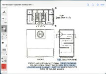
I then took the dimensions from every inch of axial distance and plotted the curve for the horn profile. I then fitted the curve with a two-point spline in Solidworks, then made a 3d model using the lofting tool, then I unrolled the curved shape to a flat 2d pattern using the sheet metal "flatten" tool. This pattern, once cut onto foam core (scored with parallel cuts every 3 to 5 mm on on the concave side) self-formed into the tractrix profile when enforcing the mechanical mates of the mouth, throat, and edge boundary conditions via hot melt glue to the top and bottom panels. For the 0.70x case, the throat is 2.0 in square and the mouth is 20 in wide and horn is 15.3 in deep. Glue the throat section first, then the mouth, then the middle.

Cut plan for 2d panel on post 94 here http://www.diyaudio.com/forums/full-range/261427-40-full-range-synergy-10.html#post4049533

Here is the cut/glue plan for the flat top and bottom panels on post 175:
http://www.diyaudio.com/forums/full-range/261427-presenting-trynergy-full-range-tractrix-synergy-18.html#post4053078

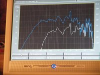
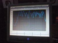
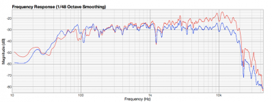
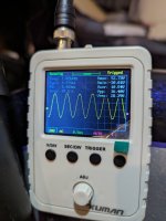
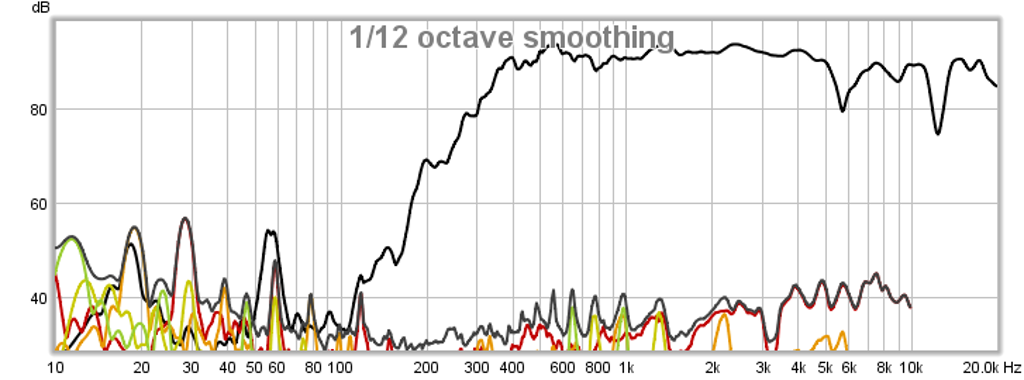
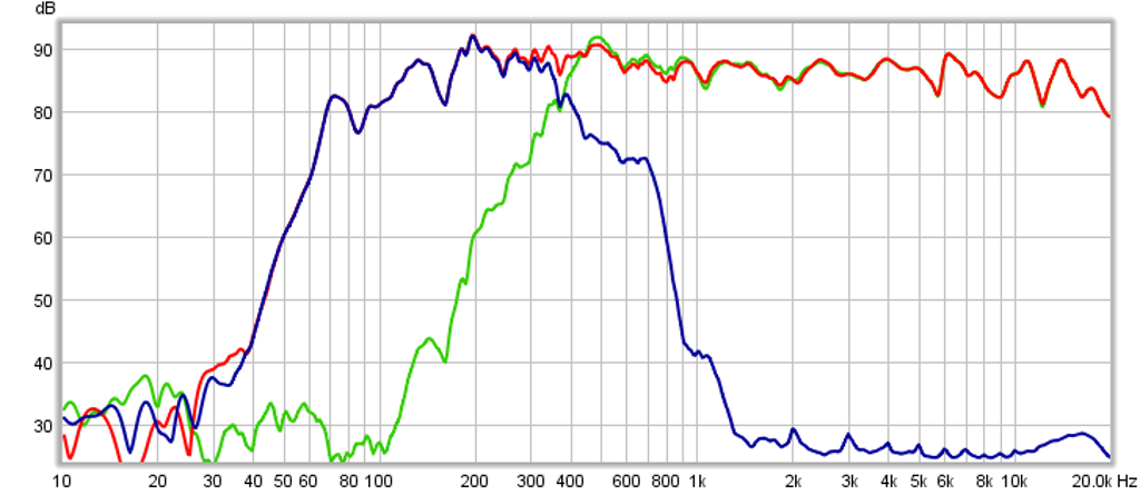
The idea for this speaker came from a large 300Hz 28in wide x 17in tall x 22in deep tractrix horn driven by a full range driver. I then scaled that horn down to 0.70x for a 400Hz 20in wide x 12in tall x 15in deep tractrix. Originally designed with the Faital Pro 3FE25 in mid, I stuck a Vifa TC9FD in it for grins. With some DSP EQ'ing I was able to get the following response from the little Vifa:

436002d1409484908-prv-5mr450-ndy-fast-applications-0.7x-tractrix-tc9fd-cld-325hz-hpf-hd-eq3.png


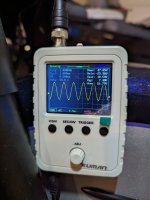
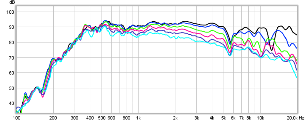
With semi-decent polars:

436003d1409484908-prv-5mr450-ndy-fast-applications-0.7x-tractrix-tc9fd-cld-325hz-hpf-polars-eq3.png


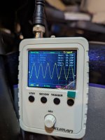
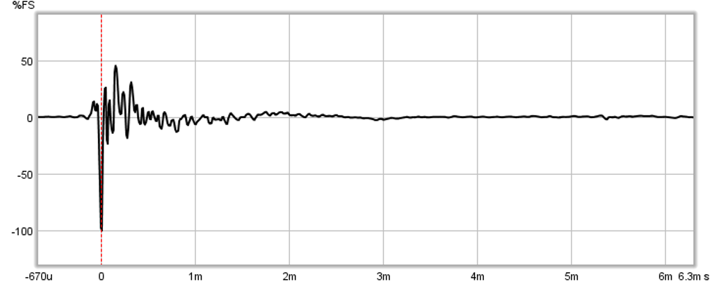
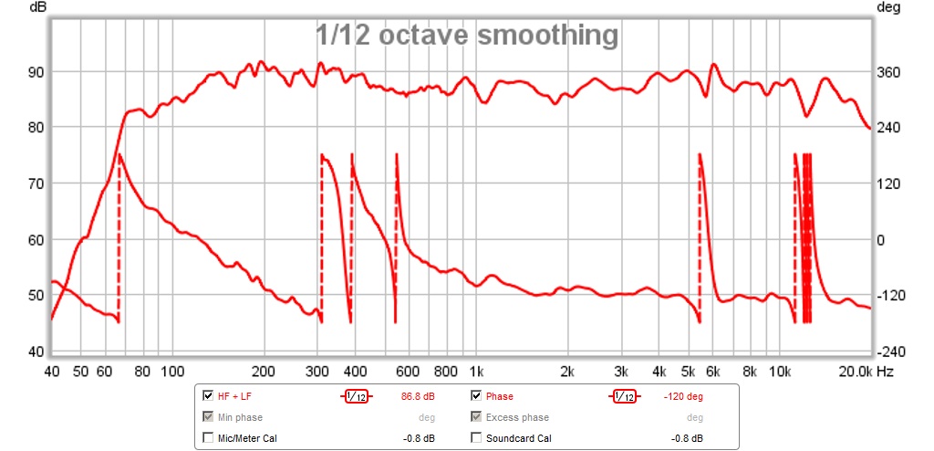
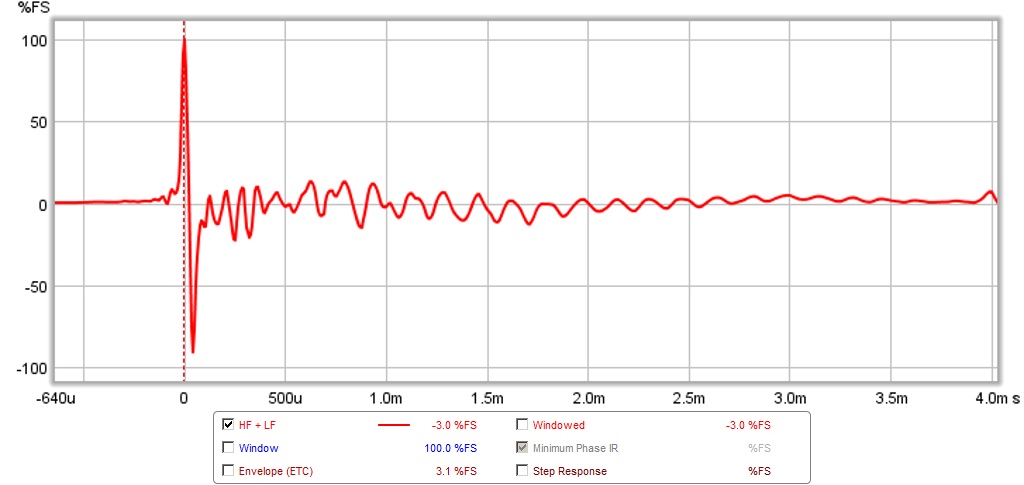
And the Impulse response isn't too shabby either:

436004d1409484908-prv-5mr450-ndy-fast-applications-0.7x-tractrix-tc9fd-cld-325hz-hpf-ir-eq3.png


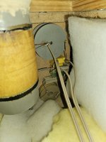
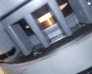
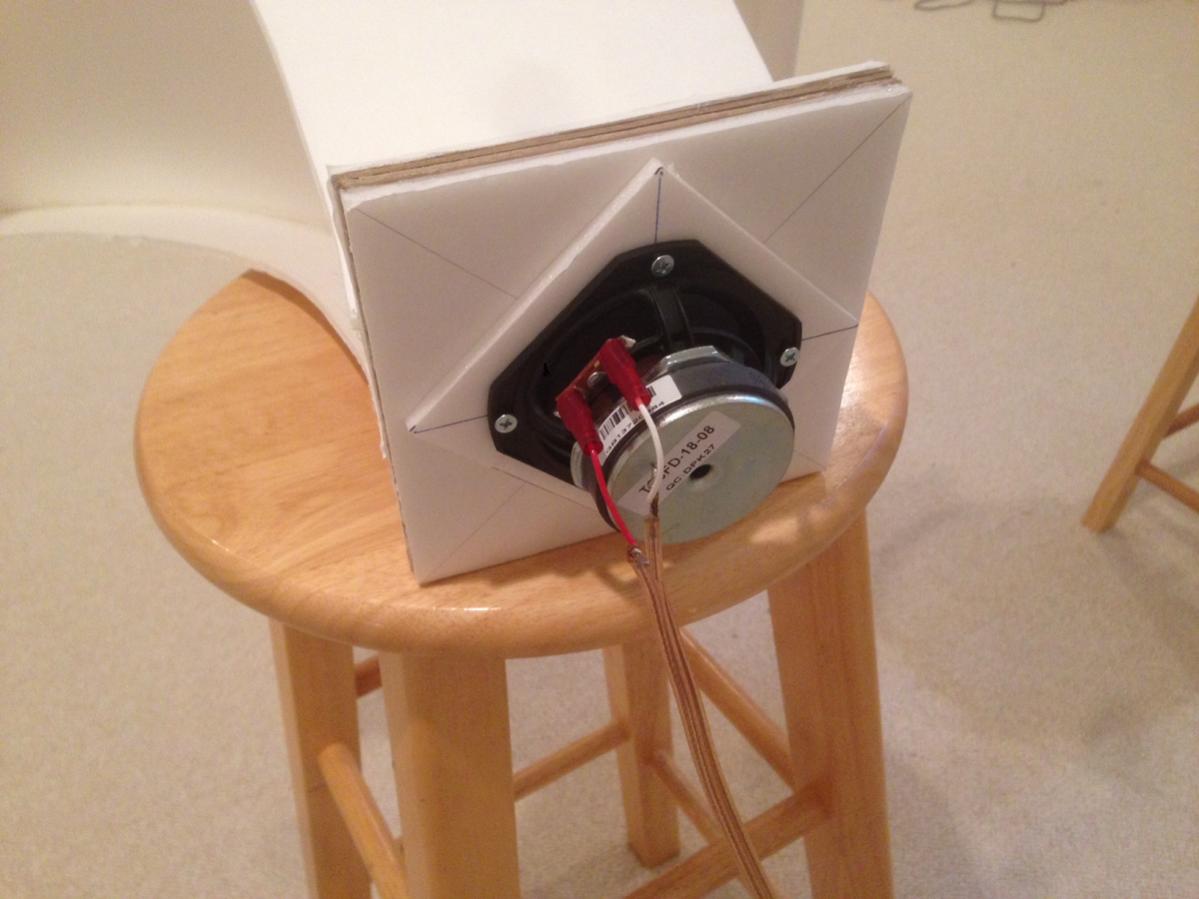
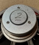
Here is a closeup of the horn driver throat flange fitted with the TC9FD (note that a FC spacer with a cutout had to be made to prevent the surround from rubbing the flange plate):

435937d1409454699-prv-5mr450-ndy-fast-applications-0.7x-tractrix-2.jpg


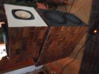
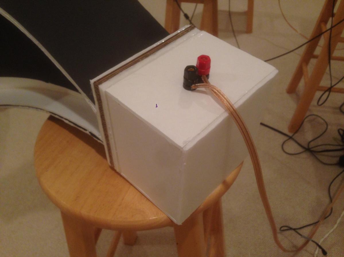
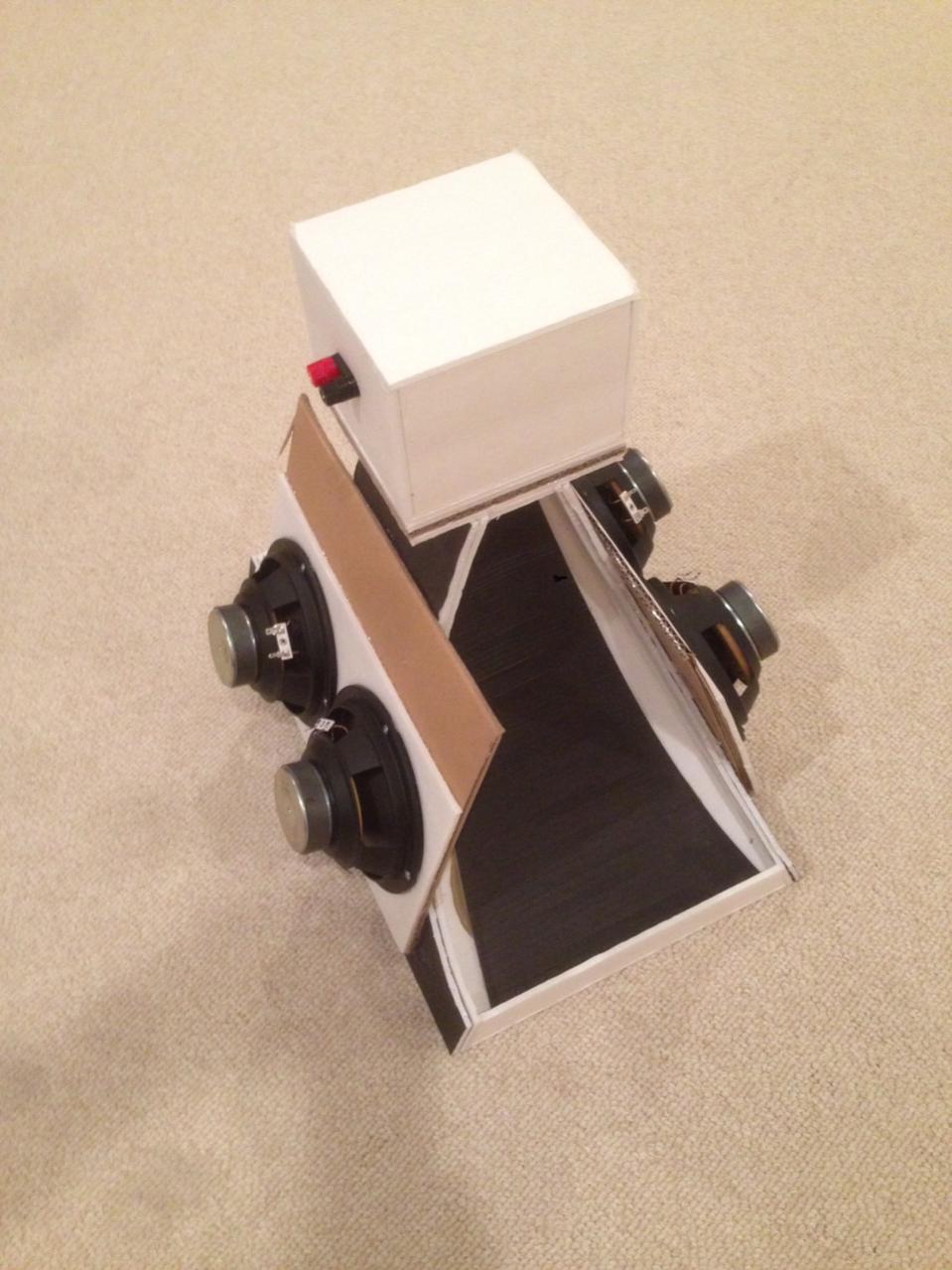
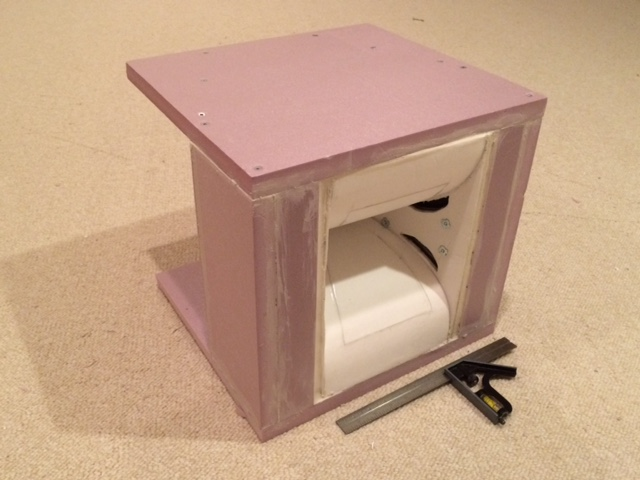
Here is the rear sealed chamber (6in x 6in x 4in and lined with open cell grey foam):

435939d1409454722-prv-5mr450-ndy-fast-applications-0.7x-tractrix-4.jpg


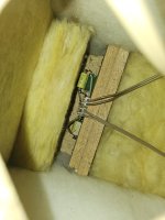
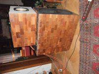
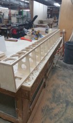
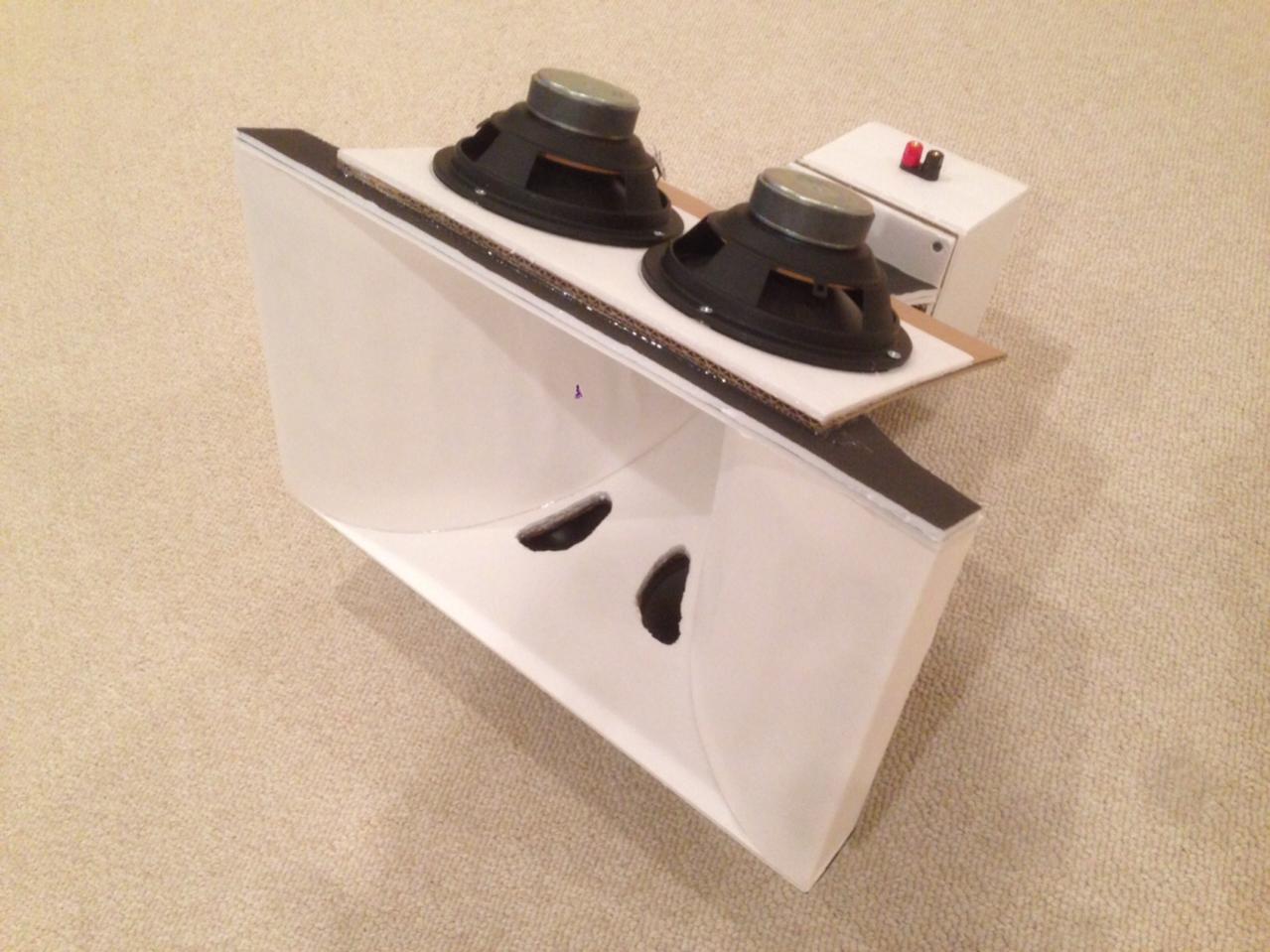
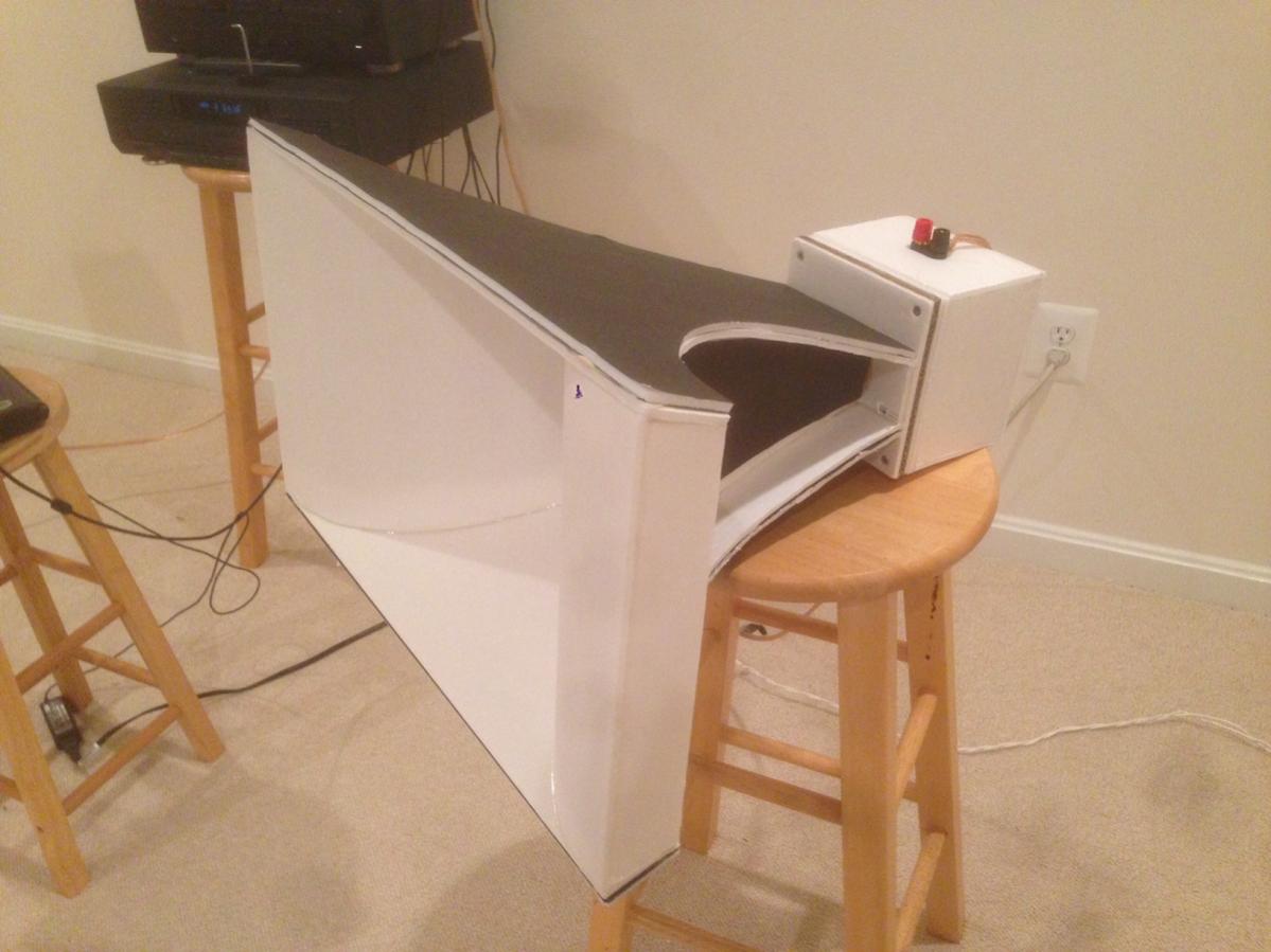
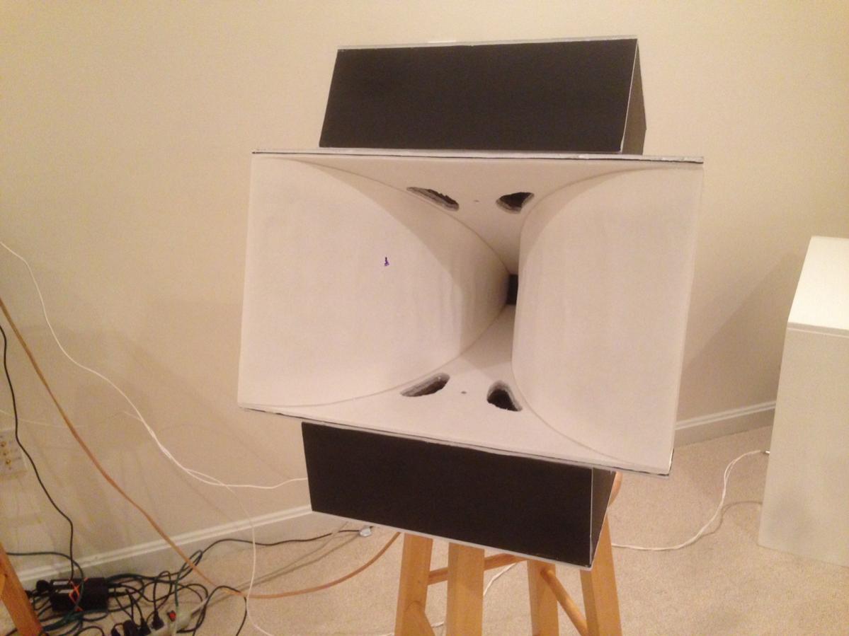
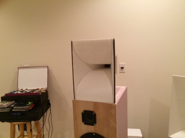
Here is the horn before I put the woofers on (note the black panels on top of the white panels - those are the constrained layer damping (CLD) layers used to reduce panel resonances using latex caulking in between the white horn walls and the black foam sheets):

435936d1409454689-prv-5mr450-ndy-fast-applications-0.7x-tractrix-1.jpg


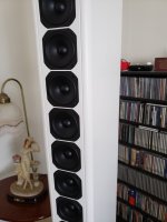
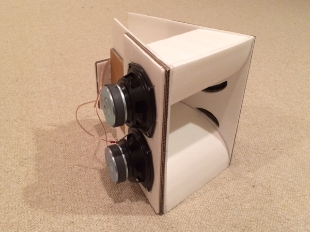
I normally model stuff before building, but in this case, I had some buyout PE 6.5in woofers lying around. There is only so many ways to fit these drivers into the tractrix so I went for the build it as you go approach sans modeling and got this after 90 minutes of cutting foam core/cardboard and hot glue:

436307d1409629163-prv-5mr450-ndy-fast-applications-tractrix-synergy-0.7x-p1.jpg


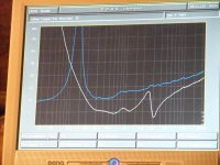
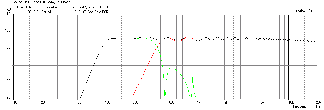
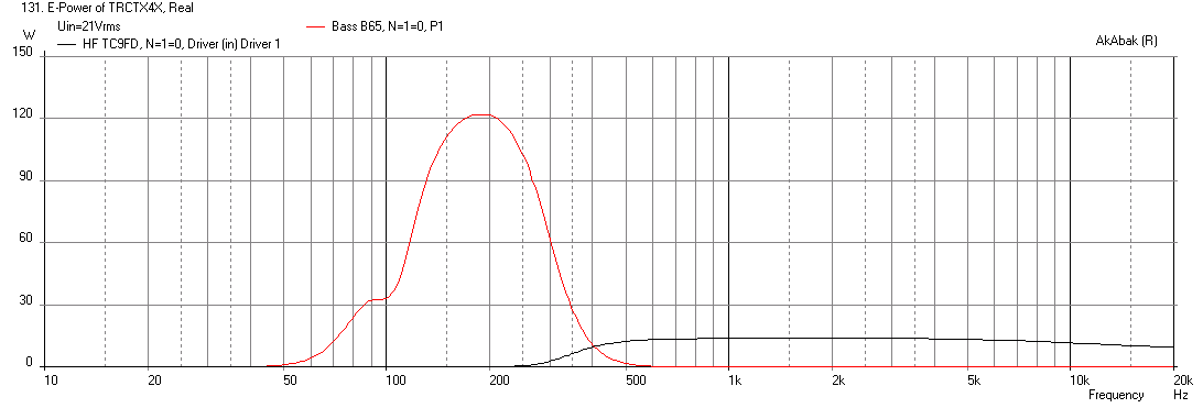
After building it, I then modeled it and saw that it needs a rear sealed chamber on the woofers otherwise there is no bass to speak of due to proximity of the backside of woofers and the mouth causing cancellation. Here is the predicted response with the woofers and the TC9FD:

436353d1409659368-prv-5mr450-ndy-fast-applications-0.7x-synergy-b65-tc9fd-sealedback-freq-1m.png


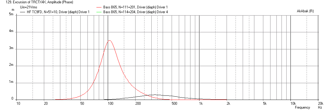
With 3.5 mm xmax being reached at 21 volts:

436355d1409659493-prv-5mr450-ndy-fast-applications-0.7x-synergy-b65-tc9fd-sealedback-displ-max-spl.png


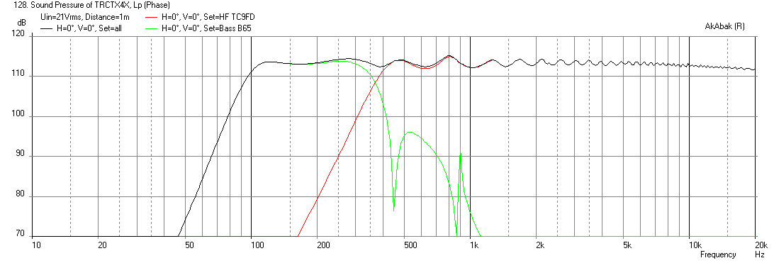
Giving a corresponding max SPL capability of about 113dB at 1m and 21v:

436354d1409659368-prv-5mr450-ndy-fast-applications-0.7x-synergy-b65-tc9fd-sealedback-freq-1m-max-spl.png


With the corresponding electrical power input predicted to be 30 watts per 6.5 in driver, which is OK per the manufacturer's rating:

436356d1409659733-prv-5mr450-ndy-fast-applications-0.7x-synergy-b65-tc9fd-sealedback-electrical-power-max-spl.png


The $40 cost break down is as follows:

- Qnty 4 Parts Express buyout 6.5 in polycone woofers (same driver as used in ther well-regarded B652 speakers) $5 ea x 4 = $20

- Qnty 1 Vifa TC9FD driver $12

- 4 sheets of foam core $4

- 1 tube of latex caulking for the constrained layer damping $2 (n.b., DO NOT use Liquid Nails - as the solvent vapors will melt the foam in the foam core!)

- 1 dual banana post binding terminal $1 ( Edit: technically $3 now with qnty 3 binding posts)

- Hot melt glue sticks $1

Note that you will need active EQ and bi-amping to make this work. It is not a passive speaker. If you have a miniDSP 2x4 and a couple of amps you are set. If you need tips on how to do this, check out the "Cheap and FAST OB, Literally" thread.

I still need to install the rear sealed chamber and get a measurement with the woofers on.

Let's see if a point source synergy speaker can be built for $40 and if it sounds good. Stay tuned!

Measurements and sound clips to follow.

Update Sept 3, 2014: the tractrix fullrange Synergy is completed and it sounds wonderful! See post 13.

436549d1409743674-40-full-range-synergy-synergy-0.7x-build-04.jpg


436553d1409743741-40-full-range-synergy-synergy-xo-70hz-hpf.png


Edit Sept 4, 2014: New tweaks on EQ provide linear phase from 600Hz to 5kHz and cleaner impulse response. Note all data smoothed at 1/12th octave.

436656d1409783083-40-full-range-synergy-image.jpg


436662d1409783210-40-full-range-synergy-image.jpg


Edit: Sept 7, 2014 - Faital Pro 3FE22 driver with 4-way miniDSP XO and bass horn sub.
437044d1410006435-40-full-range-synergy-image.jpg


Edit: Sept 12, 2014 - How to adjust and optimize time alignment between HF and mid woofers - http://www.diyaudio.com/forums/full-range/261427-presenting-trynergy-full-range-tractrix-synergy-20.html#post4055704

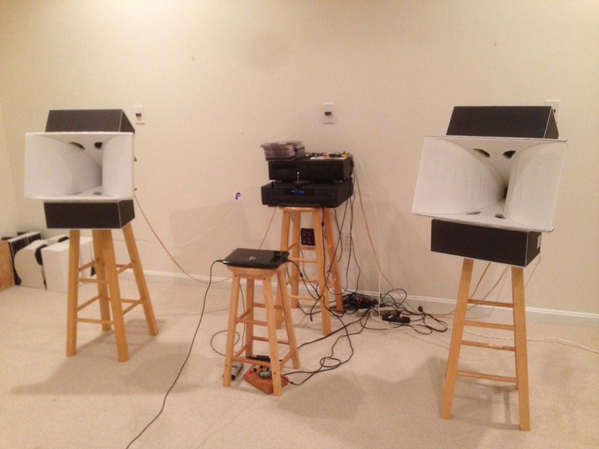
Edit: Sept. 20, 2014 - Stereo pair completed, sound clips in post 269 http://www.diyaudio.com/forums/full-range/261427-presenting-trynergy-full-range-tractrix-synergy-27.html#post4063999
439379d1411195658-presenting-trynergy-full-range-tractrix-synergy-tractrix-part-2m-stereo.jpg


Edit (Dec 14, 2015) - micro Trynergy with 13 X 8.5in mouth and 2in driver:

More info here http://www.diyaudio.com/forums/full...l-range-tractrix-synergy-108.html#post4544312

518818d1449810072-presenting-trynergy-full-range-tractrix-synergy-img_3766.jpg


Edit (Dec 20, 2015): uTrynergy in a dipole bass enclosure - more info here Presenting the Trynergy - a full range tractrix synergy.

519916d1450425655-presenting-trynergy-full-range-tractrix-synergy-utrynergy-woofers-installed.png


520166d1450563122-presenting-trynergy-full-range-tractrix-synergy-utrynergy-box-02.png
  • Like
Reactions: camplo

Will a Snubber stop my BMS tripping?

I have high power (max 2000w RMS) battery powered amps (4x 3e audio tpa3255 amps) that I power from 3x nominal 14v lifepo4 batteries. But when I plug the battery in I get an arc on the SAE connector and it seems to trip the BMS. Unplugging and reconnecting reliably solves the issue but I worry one day it won’t and I’ll be stuck on the beach with my party friends and no sound! Any ideas how to solve this? Would a snubber or other inrush current management solution help? How do I specify the snubber components so that I don’t reduce the dynamic power supply capability of the battery (it’s about 40v and can supply 40a short term)

Kimber 8TC green oxidation

I realise this is not a loudspeaker question, but hopefully it's close enough.

I am currently re-terminating an old run of Kimber 8TC. I was a little shocked after stripping the wires, as they looked as in photo below. This looks like crappy quality. I am pretty sure it is real Kimber. I got it from another hifi enthousiast who was upgrading. And it was before Aliexpress existed. The cable could be 15 years old.

Should I be worried? Any advice?

20240123_113327.jpg

Suitability of car driver for home dipole line array

Hi,

I am thinking of making a dipole line array using car drivers, 4 inch 2 way drivers. I feel there are some advantages, firstly there is 1st order crossover already built in so that I dont have to design one and secondly I have seen car drivers have high Qts and decent X max both of which help in a dipole application. Here is one such driver:-
https://www.flipkart.com/jbl-stage2-424-fhi-coaxial-car-speaker/p/itm5ce91be4a6080?pid=CSRGNSFVPVQZ7YTN&lid=LSTCSRGNSFVPVQZ7YTN2DB5Y1&marketplace=FLIPKART&store=1mt/eoe/vuu&srno=b_1_19&otracker=product_breadCrumbs_JBL Car Speakers&fm=organic&iid=48597b03-fec4-41d8-b771-b37441f54039.CSRGNSFVPVQZ7YTN.SEARCH&ppt=pp&ppn=pp&ssid=yyne9fek3k0000001706187853820

The array will be paired with 15" pro audio woofer (in dipole) to handle bass.
What do you think?

Thanks and Regards,
WA

Iron Cone vs Carbon Fiber Cone

I currently got two speakers without cones and four unused passive radiators, so I thought: why not use the passive radiators that are just front suspension and cones for the unused speakers?

The passive radiator weighs 60 grams which is heavy for a 6 inch woofer but suitable for a subwoofer, it is also made of iron which is unusual for a subwoofer and explains weight.

About the carbon fiber cone, it's just for comparison which one would be more suitable for the small subwoofer, at least I think carbon fiber cone is better in everything (weight vs stiffness & damping).

And about the motor (magnet), it must be able to move the cone since the original cone was more or less half the weight of the iron cone.

TSE-II 2A3 Planning, Power, etc

Hello all,

As noted in the main thread, I've decided to go with 2A3 in my TSE-II initially and leave the option to go for 45 later. I will be moving to Japan eventually, so I am planning to go with a 300-series Hammond "universal" PT. I considered the options that George discusses on his website, but just today I was sifting through the whole catalogue of 300-series and noticed the 370KX. It appears to be an ideal transformer for this project:

Shipping Weight 2.3 lbs (1.04 kg)
UNSPSC39121301
UPC623980050072
REACH CompliantYes (more info...)
RoHS CompliantYes (more info...)
Power Rating (VA)229
Primary VACUniversal - 100, 110, 120, 200, 220,230, 240 VAC 50/60 Hz
A.C. High Voltage Secondary RMS500V C.T. @ 322ma.
Bias Tap on High Voltage Secondary w/ C.T. Grounded (VAC)50
Filament #1 (VAC)5V C.T. @ 6A
Filament #2 (VAC)6.3V C.T. @ 6A
Mounting StyleVertical ("X")

The HV Secondary is quite "stiff" at 322mA, but I used PSUD-II to model the TSE-II power supply with this transformer and all looks to be in order, resulting in a B+ of 295v. This should be an "easy" B+ load for this transformer and I think (correct me if I am wrong) this will give me a bit of breathing room while running the 6.3V winding at full tilt for those 2A3 filaments. Please check my work below and comment if anything is incorrect.

The only thing I am not sure about regarding my model setup is the load value. I know the 2A3s will be drawing about 53mA each (at this B+ voltage) and I just tacked on another 40 or so mA for the 5842 tubes, losses, etc. adding up to an estimated 150mA load (as seen in the schematic). This was a complete guess and I would like a more accurate estimate of the total B+ current draw. If anyone can help, that would be great!

Screenshot from 2024-01-09 15-16-24.png


Here is how it shapes up in SE Amp CAD. Plate voltage ends up very close to the "ideal", at 273v.

Screenshot from 2024-01-09 15-20-31.png


Note that SE Amp CAD has an incorrect value of "250 v" for the Vmax for 2A3. Every spec sheet I have checked lists it as 300 v.

hifonıcs thor 250x2 channel oto amfi elektirik verince hemen ısınıyor aynı amfiden görsel foto lazım elınde olan

Hello masters, good evening to everyone. You have a Hifonics Thor 250x2 channel amplifier. Amp. In no way. It does not turn on green and red lights, does not receive electricity and does not work. When you apply electricity, the Mosfets get hot immediately, extremely. I changed the TL494 integrated circuit, there are 2 of them, A1266, I changed them, the problem is, when I give the voltage, it gets hot immediately. We couldn't find the same MOSFETs and the amplifier. It went to other masters before us. There is not much brand called hifonics in Turkey, but I think we can repair it and solve it. Thank you everyone in advance. If you have another image of the interior, I would be very happy. Best regards.
20240113_194223.jpg

Attachments

  • 20240113_193105.jpg
    20240113_193105.jpg
    590.4 KB · Views: 90
  • 20240119_212725.jpg
    20240119_212725.jpg
    365.6 KB · Views: 97
  • 20240119_230653.jpg
    20240119_230653.jpg
    321.9 KB · Views: 102
  • 20240119_234139.jpg
    20240119_234139.jpg
    407.2 KB · Views: 85

Bagby designs - Helix domes or wait?

HI all!

It's just about time for another build and have been a huge fan of Bagby's quarks on my work desk. I'm looking for a bookshelf with music as the priority in a medium sized living room.

Does anybody have any thoughts on the helix domes offered by DIY Sound Group, especially compared to other kits by him?

Some board members here mentioned that meniscus does plan to release his designs eventually. Hopefully we hear some news about that soon!

Potentiometer left/right inbalance

Hi.

As I had my Arcam Delta 290 integrated taken apart and I was not sure of the audio quality, I took the Alps 10KAX2 motorised potentiometer apart and checked the possibility of cleaning it. Unfortunately it seems to be not openable unless one would risk to break something. I sprayed it with contacts cleaner

I also took measures to compare the left and right channel. As recommended here, would you throw it away?

Attached are the measures of resistance. 1 to 25 are progressive positions of the shaft, non linear.

CropperCapture[12].jpg

A selection between (probably) incomparable receivers (Yamaha RX-V800 vs Marantz SR4300 vs Denon 1706)

So this is my first post and believe me that unfortunately I am as uneducated as you may expect :wave2:
I've been reading here a lot but it's quite difficult for me to gather an answer and I got a bit lost.

Here's the story: I am currently using a cheap-model JVC RX-5022V receiver with a classic old-school 5-speaker configuration (big fronts, smaller rears and a enter).

I am using it 99% of the time for stereo playback from Spotify played on my phone via a bluetooth adapter to one of the RCA outputs (not an audiophile's idea of reasonable, indeed).
That configuration is what I'd like to keep doing for now.

The JVC's sound quality output is simply crap.
Looking for an upgrade for the receiver from the used market I'd come across local listings for the following three receivers:

  • Marantz SR-4300
  • Yamaha RX-V800
  • Denon 1706

They are all similarly priced for me, which is to say that they all fit my quite-low budget.

Unfortunately I know nothing about any of these.

I've tried comparing them specifically here and online but cannot find many posts, I assume this is because these models may be completely different in terms of tier, modernity, capabilities.

Still, going forward I need to choose one. I am sure they will all be a step up from my JVC (trust me).

For Stereo music playback, is there a clear winner of the three here? If not, is there a clear loser (except my JVC)?

I'd really appreciate some help, thanks!

Note: The speakers, which are much better when used on a different receiver, may also need upgrading, but that's a problem for the (near) future - I'd like to start with the receiver.

Thanks again!

Amplifier humming noise problem

Hello.

I've been designing amplifier board using lm1875 - after a long time of studying and designing, yesterday i finally tested the first prototype of the amplifier board.
It supplies power using "unregulated", "capacitance multiplier" circuit after -18/CT/18VAC transformer output.
But when I turn on the amplifier, it sounds pop up and start to making hum noise like eeeeeeeeeeeeeeeeeeeeeee-. I guess that noise is almost close to 120Hz.
(My living country using 230VAC/60Hz to mains power, and also sadly I can't analyze the spectrum because I don't have an oscilloscope yet.)

The popup noise seems can be solved using relay or triac, but the main problem is the humming noise.
Whatever I turn the volume up or down, connecting audio source or not, it creates same humming noise before I turn the power switch off.
One strange thing is, affter turn the power switch off while amplifier working, I can hear nice, clean amplified music without any noises for a second(because of large amount of capacitor), and it finally pops up again and completely turns off.

So I found the internet to solve the humming noise problem, but it makes me confused more.
Many of articles say that problem may be a ground loop noise, or output ripple noise.
They say it can be solved using ground loop breaker circuit or using larger amount of capacitor.
But I wonder it really is because I already using two 10000uF capacitors and more etc on psu circuit, also I applied ground loop breaker circuit from https://sound-au.com/earthing.htm.

I also see some of comments that using linear regulator may be helpful to suppress power noises... would it be really helpful?

Is there anything I've got missed? How can I solve this humming noise problem?
Any suggestion would be really appreciated.
Thank you.

Chinese AIYIMA 1969 Clone IRFP448 static current

First of all, I wish you a nice good day!

I bought two of these cheap AIYIMA 1969 clones for crafting.
In contrast to the standard circuit, MOSFETs are used here (IRFP448).
The variant with MOSFET doesn't seem to be widespread, I couldn't find much via the search function.

On the seller's supply side, a static current of 30mA is recommended. This confuses me a bit.
With this setting, the amp works, but it feels like it doesn't develop much power and it doesn't get warm.

Can the value of 30mA be correct? If not, what values are recommended?
Operating voltage is 20V.

Thank you

Lenny

New speakers I’ve purchased

Alright guys, need some help with choosing amps.

So I came into possession of some gear for a very inexpensive price and couldn’t pass it up. That being said, I’m inexperienced when it comes to how to power it all and for wiring it up.

I’m trying to wrap my head around the power requirements and using bridge mode for subs and two channel stuff for the tops.

Can someone help me out? I’m in over my head.

Gear list:

I’ve also listed the continuous power rating/ohms. As far as I know, the drivers are all original.

1. Carvin LS1801 x2 800w 8 ohms
2. Peavey 118 x 2 400w 8 ohms
3. Peavey PV215 x2 800w 4 ohms
4. Carvin 993 x2 800w 4 ohms

Much appreciated for any help.

Attachments

  • IMG_6502.jpeg
    IMG_6502.jpeg
    1.1 MB · Views: 100

Panasonic DVD A-110 tray abrupt closure

My A-110 is 25 years old & I luv the sound of its DVDA DACs. I bought a second used one, the laser is in better shape than mine BUT it suffers from unintended tray closure, a nuisance. I tried reseating ribbon cables with no improvement. I checked online, no luck. Has anyone encountered this problem on this series of players & has comments or a fix?

Struggling Measuring Driver Frequency Response with Umik-1 and Dats V3

Hi.
I've been building speakers for some time, and finally decided to fully invest in equipment, to take my designs to a higher level.

Therefore i bought an Umik-1 and a dats v3.

I have one problem however:

I want to measure FR on a new build that i have. I want to build the crossover design around these measurements. However i cant seem to figure out how to safely take a measurement. I was of the understanding, that the dats v3 could make a frequency sweep, and that the umik-1 would record this. I know the dats can do lots of other things as impedance curve etc, so by no means unnecessary.

But in reality. How do i safely measure the response of my drivers in the build, without burning it down? I guess i could volume down an amplifier and test, however i would much rather test in a more controlled enviroment.

Also when measuring the tweeter and woofer, should they measured together or each on their own? As far as i am aware, i will measure it one meter out from the tweeters level.

Thank you very much.

The latest version of the Android app for Wuzhi amps

I really like those Wuzhi 2.1 amps, I use them for everything from boomboxes to adding tunes in the shower. I've probably got 5 of them at this point, and I get them for friends too. For $30 plus a couple of thriftshop speakers it's hard to go wrong.

https://www.amazon.com/gp/product/B089KT3FG9

1671305792732.png


And I just found out there's an Android app for it that can change the Bluetooth name. And it works! Mostly. It's about the jankiest app I've ever used and isn't in the Play Store for mysterious reasons that make me nervous, but it was easy enough to install on an old Kindle that isn't logged into any of my accounts.

It's here if anyone wants to try it:

http://www.qingdaowuzhi.cn/btapp/Wuzhi_Audio_V1.0.4.apk

Took me awhile to find that link since every mention of the app links to version 1.0.2, which is even more janky than that newer version. I had to modify the URL to find the new verison, ha.

After using the app my amp broadcasts two bluetooth IDs: "Whatever" and "Whatever APP".

I don't imagine anyone knows what the "APP" version does?

I'm guessing the Amazon listing I bought the amp from doesn't advertise the app since every review would focus on how terrible the app is.

Edit: Oops I think it actually created two bluetooth instances with the same name (in this case, both named "Whatever"). But I can only connect to one of them, the other should have "APP" appended to the name but it doesn't. That's super annoying since it means new people connecting to it have a 50% chance of trying the one wrong first. Ugh. I don't understand how these things can have such low quality control.

Shure In-Ear Monitoring System PSM600 P6T Circuit Board

First of all - not sure if this is the right Forum, but I'll give it a shot.
I've recently purchased an old IEM-system Shure PSM600. It's outdated, but it fits my needs.
However - when I plugged it all in. I noticed a low frequency humming, which was really annoying and dominant in the earpieces. So I started fault finding and couldn't work it out on the mixer or cables. Everythin is good. But then i touched the casing of the PSM600 transmitter (the P6T) and I could hear in my InEars, that I was touching it. Meaning - It was like there was a microphone inside the casing.
So I'm not super strong on circuit boards, but I'm guesing there is a short somewhere or a bad component. No physical abnormalies detected. I searched different forums for similar problems - nothing found. I only found some spanish or whatever speaking guy, who replaced a Talema 70054K unit on the curcuit, but thats all.

What are your thoughts? Can I test the board with a multimeter? how?

cheers

I want to add a coaxial output to my Sony CDP 400 multiplay as its optical out only

I have Just bought a Cambridge audio dac magic 1, it has only BNC coaxial inputs and no optical input.
I would like to connect my multiplayer to this but its digital optical out.
I was thinking that surely there is a digital signal going into the convertor or whatever it is thats outputting the optical signal.

Have any of you already tapped into the digital signal on a cd or similar and then tapped it off to provide a digital coaxial output?

The alternative is trying to add optical input to the dacmagic.

Thanks in advance

Attachments

  • cdp400.jpg
    cdp400.jpg
    35 KB · Views: 89
  • dacmag1 bnc.png
    dacmag1 bnc.png
    456.2 KB · Views: 89
  • dacmag1front.png
    dacmag1front.png
    375.8 KB · Views: 87
  • dacmagbal.png
    dacmagbal.png
    413 KB · Views: 84

What RaspberryPi-like PC supports multichannel digital input (I2S/TDM)?

Hi all, sorry for my newbie question.
I'm looking for a 4 channel ADC solution.

Previously, I ported my TLV320ADC6140 to my RaspPi, but Pi seems doesn't support multichannel I2S nor TDM input.
(https://github.com/filipmu/audio-recording-firmware-raspi-tlv320adc6140/issues/1)

I wonder if any other similar platform such as OrangePi could help me to do that?

Really appreciate! 🙂

LEDs flickering, how to eliminate it?

I know this is not an audio related topic, but I hope you can help me anyway, since it is about electronics after all ... 😉
The LED strip that I installed in a new kitchen cabinet blinks when the switch is off. The culprit is the neon, which allows a minimum current to pass that fluctuates depending on the network frequency.
Searching for info on the web, it seems that it is eliminated with a parallel capacitor, but I can't find how to calculate the value exactly. Some YT tutorials mention 0.47 mf. x 275 VAC, other 1 mf. x 400 VAC. I tried what I had at my disposal, 1.5 mf, x 250 VAC, polyester capacitor. It didn't give any results, so I looked for some more specific information, but all the manufacturers abound in the benefits of their products, but they don't provide that information, which seems to be a state secret kept under seven keys. I imagine there must be a way to calculate it according to the frequency of the network and the voltage, here we have 50 Hz and 220 volts. But it seems that these modern luminaires work with DC or AC, I imagine that the one installed is AC, from the looks of it, it does not seem to include a rectifier and it should indicate it if so...
P.S:
I don't want to override the neon indicator light, it's useful for quickly locating the switch in the dark.
Thanks in advance !

Attachments

  • Capacitor for LED´s.jpg
    Capacitor for LED´s.jpg
    10.7 KB · Views: 375
  • IMG_20240120_175451.jpg
    IMG_20240120_175451.jpg
    191.7 KB · Views: 158
  • IMG_20240120_175748.jpg
    IMG_20240120_175748.jpg
    488.9 KB · Views: 148
  • IMG_20240120_175804.jpg
    IMG_20240120_175804.jpg
    308.4 KB · Views: 152
  • IMG_20240120_182653.jpg
    IMG_20240120_182653.jpg
    283.9 KB · Views: 154

RCA 64B Monitor Speaker 1941

Hello all
I brought this pair of RCA 64-B monitors up a while back, but I became quite ill and never followed up. If you responded please forgive me if you didn’t hear back from me.
When a doctor starts talking about one’s future lifespan in terms of months it does funny things with your head.
By the grace of God they were wrong and I’m still here!
These came with the original drivers but they are in poor shape. I’m hoping some can recommend some replacements. I tried a pair of Altec 409A’s which had amazing bottom end in these cabinets but little on top. I may be wrong on the Altec #. they were ceiling mount units that I though were 8” diameter, but the data in the attachments seem to indicate 6.5” drivers.

since I’m fortunate enough to still be here to toy with them I’m hoping someone can recommend a driver.
I remember them being incredibly efficient and sounding great. I’m really curious what they’ll sound like with drivers that weren’t intended for mounting in
elevator cars!
Thanks in advance,
Rick

Attachments

  • IMG_5803.png
    IMG_5803.png
    925.7 KB · Views: 310
  • IMG_5801.png
    IMG_5801.png
    949.5 KB · Views: 258
  • IMG_5800.png
    IMG_5800.png
    830.9 KB · Views: 253
  • IMG_5799.png
    IMG_5799.png
    386.6 KB · Views: 283

1959 PYE Radiogram

I have a 1959 PYE Radiogram with a Garrard turntable. After getting it i knew it would need some repairs, i changed the cartridge on the record player, and everything worked fine for a while, so i didnt bother making any new repairs. However recently i have noticed the motor gets quite hot quite quickly, and if i auto turn off the record, or it cycles to a queued record stacked on top, the pick up arm struggles to return to its default position, while simultaneously the turntable will stop spinning too until i push it along which also helps the pick up arm return to its orginal position. May i ask what the problem may be and how it could be fixed.

Determing Xmax for vintage woofer

I have acquired a complete set of drivers that were used for Cerwin Vega's AT-15 speakers and would like to use them for my first DIY project. I realize the drivers may not be ideal, but at least working with them will let me start to understand the basics.

I have collected the TS parameters for all of the drivers with a DATS V3. However, in order to start modeling the enclosure, I need the Xmax for the woofer. The current version of CV does not have that information and I have not been able to find it anywhere on the Internet.

The attached image gives a rear view of the woofer. Can Xmax be determined if the pole piece is removed? I have four of the woofers, so I am good with sacrificing one of them in order to get the measurement.

Thank you for your comments and suggestions.

Attachments

  • Woofer Pole Piece.jpg
    Woofer Pole Piece.jpg
    460.3 KB · Views: 92

Vox Pathfinder 10 as a modding platform

That's my second ongoing small guitar amp project after the Fender Champion 40.

I just love the small pathfinder. With a few mods and a cab it sounds very nice. Plus it's a DIYer's dream, being a full old-school circuit with a transformer PSU and all through-hole parts.

The schematic has been around for almost a decade, but there still might be things that need to be fixed.
Vox Pathfinder 10 schematic (rev.D 4-28-2021) - Album on Imgur

My goal is to have a nice super-clean platform to use with my pedals. I do not expect it to clip or sound like a tube amp on its own, but it can sure sound awesome with pedals.

So here is the list of my TODO stuff, gathering info from around the internet, plus results so far. Ssguitar and tdpri forums have much useful info.

[] Remove the hard clipping LEDs. This is the first mod that anyone should do. Just snip the LEDs and you immediately get rid of that "bees in a can" sound when the boost is on. Highly recommended mod. The only issue with it is that when the boost is on and the gain is set high, the amp is VERY loud. The volume goes from 0 to OMG very fast.
This brings me to my second recommended mod.

[] Change the linear volume pot P4 to one with an audio taper. The difference is more evident without the boost on. When you engage the boost, the amp still goes loud fast, but you get some more volume resolution than before.

[] Add a 1/4 jack to allow connection to a CAB. This is super easy and very straightforward.

[] Removing C12. This cap acts as a low-pass filter on the final stage. It rounds the sound a lot, and it kills lots of clarity. Without it, when the boost is on, the sound gets a bit harsh. But the clean sound is just amazing. Something especially evident in harmonics and pick attack. Perhaps it makes sense to experiment with different values and types here to suit your taste, but without it, you get a nice percussive and super-rich sound that is almost JazzChorus-like.

[] Replace the plastic boost switch with a DPDT toggle switch. My switch was getting scratchy. The panel now looks much better 🙂 The switch fits only if it's mounted on its side so that it flips horizontally. You do not have to solder all 6 pads. The top right is not connected to anything, and the bottom left is no longer used since we removed the LEDs.

[] Removing R8. I have tried this but I am not sold on it. It gives another boost in gain on the cleans that is immediately audible as extra noise. And it seems to also affect the voicing a bit since it includes C8 and R9 in the feedback loop (probably to compensate for adding R5 on the first stage).
I will probably restore this since I do not need any more gain on the clean channel and I am not sure I like the change in tone.

[ ? ] Change C28 to a bigger cap. I was wondering how starved the chipamp could be without some solid power capacitance close to it. So I changed C28 to a 1000uF one. I have not used a cap this way before so I was not sure about the effect. The truth is that I did not hear any noticeable difference. I will revert it in a few days to check again.

[ - ] TODO: Experiment with R27 and R28 to see how lower or higher rails on the preamp could make the amp's volume range more usable.

[ - ] TODO: Add some soft clipping diodes to get some mild clipping when digging in. I will try some stuff, but I am not 100% sold on this. A good pedal in the front or in the FX loop makes more sense.

[ - ] TODO: Eliminate the boost circuit and repurpose the switch to control the clipping diodes.

[ - ] TODO: 100nF ceramic bypass capacitors between the power rails on all opamps. This might not be critical, but I have seen a big difference in other applications, so I plan to try it. It's cheap and very easy to do on the underside of the pcb. It could make a bigger difference if you plan on using the amp on higher gains, especially on the first stages.

[ - ] TODO: Add a simple series FX loop right before the power amp. This should be easy with two switching jacks. And we probably do not need a buffer either.

[ - ] TODO: In general, experiment with PSU optimizations, like CRC, better rectifier diodes, a quasimodo snubber, perhaps a bigger transformer with lower V to reduce the Wattage and make it more home-friendly

[ - ] TODO: General experimentation with different caps and resistors on various positions. I am not going fancy, just going to try different parts that I have in my stash. Changing the gain might not be easy without changing the voicing though.

Acoustat Model 3

Hello to all, I have a friend looking to buy a pair of Acoustat model 3's with the blue or red Medallion interfaces in nice condition. Preferably oak bases and black grill cloth as shown in the attached picture. He was hoping to find a pair within a 100 miles of Frederick, Md. 21701. If anyone has a pair they are willing to part with please reach out to me.

Thanks in advance.

Attachments

  • 20191202_170316_resized_2.jpg
    20191202_170316_resized_2.jpg
    221.5 KB · Views: 170

Streamer/DAC raspberry pi 5

Hello All,

i'm not abble to pay 1000 eur for DAC on the market, but i want great sound, i'm newbie and i would like this project to be succes i'm thinking to use a raspberry pi 4/5 ,
i want to build a DAC minimum 24/192khz more it's better, i don't know what hat card do you advice me to take
for the streamer i'm not abble to code i need something with permit me to stream qobuz/tidal/ deezer, i have seen volumio but i'm not ready to pay15 euros per month to use volumio in more qobuz's price.
Have you any experience to help me?

2x12 reflex for two different applications

Hello everyone,

We have a small soundsystem (5-way) where we use a 2x12 reflex box to cover the frequencies from 200 Hz to 2000 Hz. We built this box a couple of years ago with no expenses and no knowledge, but now we have a couple of good drivers (PD121) and so we've been trying to use WinISD to build a new box with better wood, ecc. in order to replace the old cabinet.

We would also like the new box, apart from being able to cover the 200 Hz - 2000 Hz range, to have the possibility of being used in a smaller scenario, for example inside a cafe, as a bass cabinet (hp filter from 60 Hz with dcx2496?). Hence why we would like it to be a reflex design.

Using WinISD for the first time, right now where we stand is:
  • Box Voume: 109.5 L
  • Tuning Fr: 70 Hz
  • Vents: 2x squared - Area = 277 cm^2 - Vent Length = 5.70 cm - 1st port resonance: 3005.15 Hz

The thing we would like to know are:
  • Regarding the tuning frequency, should we aim for a lower tuning? Looking at the driver datasheet, stated Fs is of 53.27 Hz, and we've always heard to stay above it with the hp filter.
  • Another thing we've heard is to keep the 1st resonant frequency of the port out of the desired frequency range. Would in this case 3k Hz be ok or should we aim for higher, 4k?
  • Cone excursion. This is something we can't really understand on WinISD, as both this, and the sealed 2x12 sealed version (same volume, just for comparison) seem to go over excursion really fast from around 150/200 Hz down. But, this depends on signal input power and we're not really sure what value to put there.

Please don't be too harsh if we've thought all of this completely wrong, it's our first time using the software and we suppose that the easiest thing to do would be to just do a sealed box for the 200-2000 Hz range.
Lastly, we have to possibility to get Crown XS1200 for a cheap price. We already have one, and it seems to suit our needs. Looking at the PD121 peak at 1200 watts, we should be ok connecting 2x PD121 in parallel to one channel --> 1100 watts at 4 Ohms, right?

Kindest regards,
Dan

Has anyone made a transformer for onboard mics or desktop boosters ?

Has anyone put the transformer inside the microphone body ? Fed with an AC wall wort the isolated power could then be stepped up inside the mic rather than having to have to make a choice between lunch box with your tube mic or fets giving you power and awaiting the day they make magic blue smoke. I've wanted to get the time to build this for a while, the core has been with me wound for 2 years without getting strung with wire and tested.

I had to relearn transformer theory and then learn it proper. It got glossed over in computer engineering but not in any depth needed to make them. Transformers are wound to turns per volt, ratio is just a side effect of those turns. The calculations for figuring out that number were a pain to find again and a bigger pain to learn to wield correctly.

Adding to that I chose an R core transformer as the topography, my r core is exactly the same way the U47 mic audio transformer is wound except with a strip of metal rather than stacked laminations. So for my Power Supply I choose to learn to wind it in the most complex "german" way possible and I figured this out only after mastering it because with no master to teach me and unreliable and conflicting internet data, I had no way of knowing I was trying to eat the elephant, tusks first. Years ago I had seen the connections for the U47 and thought it insane, last week as I finished calibrating and figured out core polarity, I happened to see the U47 diagram again and I smacked my head...

I'm using a high nickel, grain oriented strip insulated with kapton tape on one side and wound to create an 8mm square core. At these sizes the effect of the gap of a round tube on a square peg isn't zero but it's not significant, consider the tiny gaps you see are smaller than the thickness of a normal plastic transformer winding bobbin, I have Several transformers as examples. The idea was to make my own tube mics from scratch so the transformer steel was for audio but it does just fine in a power application.

This is round 2, round one wasn't even close to core saturation, pie in the sky internet R core numbers. This is the rewind with different numbers to let me do AC injection for getting data on the strip winding. The filament is a good load for the transformer and isn't at full power yet. It didn't need to be, just needed to be a reliable load to test the core saturation voltage and calculate my proper turns per volt.

I'm shrinking it to the smaller core with 3d printed bobbins. Once it's done I'll have a rought prototype to base minor winding updates on and maybe even find some prolific builder who could test in rapidly.

In addition to selling my own mics with em the goal is to tap the transformer for heater, bias and then 6 or 7 taps for various tubes, start at 100v and tap it every 50v out to 300. Pair it with a tested, CSA approved power brick and a matching barrel jack that people can use in their mic or small desktop amp design.

People have mics bigger than oldschool maglights, there is ample room to have the high voltage all onboard and increase safety by double isolating the transformer and having all HV happen inside the grounded metal case.
close.png
2024-01-23 03.35.37.jpg

For Sale FW J2 clone finished and tested boards

Hi everyone, I have a finished set of boards from a working J2 clone. It is basically all you need to make an amp minus chassis and 18Vac transformer. They've boards come from a working and properly biased amp, so basically plug and plan. All semiconductors are original: 4xJ109+4K170+4 very well matched SemiSouth R125 from SemisouthFan (I think that was the forum name). The last picture is a picture of the amp they came from, just for example. Price is $500 shipped in US. Thanks for looking.

Attachments

  • IMG_0260.jpg
    IMG_0260.jpg
    942.8 KB · Views: 180
  • IMG_0261.jpg
    IMG_0261.jpg
    568.7 KB · Views: 173
  • IMG_0759.jpg
    IMG_0759.jpg
    668 KB · Views: 177

For Sale Amplifier modules from Arcam and TAG McLaren

Have some spares for sale, those are NOS and have some nice parts inside- Noratel audio transformers, good heatsinks, someone in need of an easy amp solution can save some time.

1.Tag McLaren 10x5r modules, NOS from a repair shop 100euro each, 7pcs. 600euro for all.

2.Arcam P7 modules, 2pcs. plus one for spares with a switch missing . 150euro for all three
  • Like
Reactions: abanico

What is that?

Czy ktoś wie, jakie są te głośniki? Waga 25 kilogramów głośników Audax

:cop: 
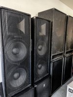
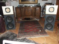
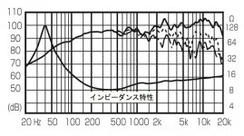
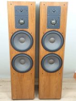
translation: "Does anyone know what these speakers are like? Weight 25 kilograms of Audax speakers"

:cop: Please post a translation. I did this with google translate.
:cop: Proszę o przesłanie tłumaczenia. Zrobiłem to za pomocą tłumacza Google.’

20231217_121749.jpg

Attachments

  • 20231217_094942.jpg
    20231217_094942.jpg
    421.5 KB · Views: 152
  • 20231217_094934.jpg
    20231217_094934.jpg
    498.8 KB · Views: 150

Fostex FE206En - Change in Frequency Response Peaks above 1000Hz due to Aging ?

Fostex FE206En - Change in Frequency Response above 1000Hz due to Aging of the Suspension Material ?

About 15 years ago I designed a 2-way loudspeaker in which this popular and good sounded full range speaker in a sand-filled, closed box covers the range above 500Hz.
At the time of the first measurements, the peak between 2500Hz and 3200Hz was also straightened by an equalization network integrated into the high pass crossover network.
During a current check of frequency response, I note that the above mentioned peak both in the frequency response and impedance plot is a bit moved down than at the time of the design.
Which means, that the mentioned equalization parallel network (notch filter) no longer works in the right manner - go to the attachments (i. e. notch filter values must now be corrected).

I would be interested to know if this moved down peak in the frequency response is common resp. usual after a long time of use.

Maybe I didn't pay attention at that time to the fact, that the running-in resp. burn-in time was long enough when I start the design of the equalizer network (2-3 days were obviously not enough).

Thank you for any statements.

P.S.: Image No 1 shows the frequency response (SPL nearfield) without (blue) and with (white) passive crossover network/equalizer. Image No 2 the same, but for impedance. Image No 3 the frequency response at the place for listening include mid bass unit (Precision Devices PD121).
Image No 4-6 the loudspeaker set up without sub (this you will find in post #4 under
How Reliable Are McCauley Drivers?
and image No 7-10 other plots for frequency response of FE206EN found on the web.

Attachments

  • Fostex FE206EN Frequenzg. ohne-mit Filter.jpg
    Fostex FE206EN Frequenzg. ohne-mit Filter.jpg
    1,020.1 KB · Views: 220
  • Fostex FE206EN Imp L mit-ohne Filter.jpg
    Fostex FE206EN Imp L mit-ohne Filter.jpg
    1,005.9 KB · Views: 227
  • PD121+FE206EN L Summe ohne Sub.jpg
    PD121+FE206EN L Summe ohne Sub.jpg
    1,004.8 KB · Views: 233
  • DSCF8130.jpg
    DSCF8130.jpg
    1,002.4 KB · Views: 210
  • DSCF8127.jpg
    DSCF8127.jpg
    998.5 KB · Views: 212
  • DSCF8124.jpg
    DSCF8124.jpg
    1,005.8 KB · Views: 172
  • FE206En-F1.jpg
    FE206En-F1.jpg
    97.7 KB · Views: 173
  • FE206EN.gif
    FE206EN.gif
    74.2 KB · Views: 168
  • FE206E before-after-tuning.png
    FE206E before-after-tuning.png
    167.7 KB · Views: 190
  • trumpet Fostex FE206E.gif
    trumpet Fostex FE206E.gif
    17.3 KB · Views: 171

1957 Reel-to-Reel Conversion to Guitar Amp

Hey All: I found an old V-M Corporation "Tape-O-Matic" model 711 Reel to Reel machine in the trash recently. I could tell it was something cool from the leather wrapped cabinet, and figured there were some cool components inside to harvest. After pulling it apart I was pleased to find 3x Amperex "Bugle Boy" Made in Holland 12AX7 Tubes along with a V-M branded Made in USA 6V6gt power tube and 5Y3 rectifier. This tube combination (6V6, 5Y3, 12AX7) reminded me of the old Fender 5f1 champ amps and I'm starting to wonder about using the parts to build a guitar amp (using new electrolytic of course). The power transformer specs seem good to my novice eye and the output transformer is spec'd (according to the documents online) around 8 watts. I could reuse the tube sockets, cloth wire, some resistors and non-electrolytic caps, etc. Looking at this schematic, can anyone tell me the viability of this project...I'd admit that I have strong soldering and wiring skills having restored a vintage Vibrolux Reverb (with a lot of online forum help), but a beginner's understanding of reading schematics and amp "designing". Attached is the schematic. I'd love to eventually work up a diagram to rewire this into a more tweed champ like chassis / head.

Tape-O-Matic-711 r-r-schema.jpeg

Is this considered "clipping"

Hello,

I was setting gains on my class d Soundigital 1200.4 amplifier yesterday and noticed this slight squiggly pattern at the top of the sound wave (1000hz 0db). I know a sound wave squares off when clipping but is this considered the same thing? I also attached a photo of the wave before increasing gains and it looks a lot smoother.

Attachments

  • PXL_20240123_233007290.jpg
    PXL_20240123_233007290.jpg
    377.2 KB · Views: 112
  • PXL_20240123_232646715.jpg
    PXL_20240123_232646715.jpg
    378.2 KB · Views: 112
  • PXL_20240123_232453944.MP.jpg
    PXL_20240123_232453944.MP.jpg
    340.7 KB · Views: 112

Subwoofer resistance help

Some slight confusion here due to this comment I just read this site. I Linked a screenshot of comment. Im new to the home audio equipment but have always had car audio systems But resistance is the same correct. I’m about to order a single dayton audio RSS265hf 10” 8ohm version more that likely the amp I get will not be 2 ohm stable so that knocks me out of getting the 4 ohm unless I wired it to 8 ohm so was going to get 8ohm and wire it to 4 ohm that would be correct or I completely wrong? This comment made it sound like the 8ohm version had be ran at 8 ohms is that even possible?? can someone help me get some understanding here
IMG_3493.jpeg

Compressions drivers, 3” beryllium vs 4” ???

Hello, I’m wanting to build a reference pair of speakers and want to start out with the best drivers I can get my hands on/afford. I was going all JBL and as of right now have many JBL drivers to choose from, but thinking of using the 1500AL, 435Be, and 045Be. These drivers are used in the k2-S9800. So my thought was maybe to clone that. I did some reading and it seems that while some preferred the s9800 to the S9900, most preferred the s9900. The two speakers using the same woofers (pretty much, the 1500AL in the 9800 had small changes made for the 9900 and it is the 1500AL-1. With the changes being minor I do see most saying they prefer original, it being slightly better), and same 045Be tweeter. One big difference between the two is the 435Be 3” beryllium in the 9800 and the 476Mg 4” magnesium.

So it has to come down to driver size or how they used them in the crossover/speaker. I say that because the general thought is beryllium is a better material and the JBL 4” beryllium is the dream driver that is lusted after. So it shouldn’t be the material that makes people like the 9900 more. Only other option would be a better crossover in the 9900 or they ran the 3” in the 9800 into frequencies that were bordering its comfortable range. I don’t know.

So I inquired about the 4” magnesium through reconing speakers and a pair of those drivers would be just shy of $3k delivered to me, and that’s no horn! Uummmm no. That’s insane. So that’s out, then I was thinking what if I went with a non JBL driver. But maybe I should just play with the 3” beryllium (and H9800 horn) that I have now.

So I wanted to see what thoughts are, do you think it’s possible to cross a 3” beryllium driver to a 15” woofer and have it sound as good as a 4” driver of lesser material quality? Is there 4” that anyone recommends that isn’t stupid priced (like $1000 a pair or under, drivers only)? Or should I play with the 3” because it’s likely I can get it to sound as good?

Dan

Creating a Simple Breakout PCB

I would like to obtain some breakout PCBs for Cinemag CMOQ-4HPC transformers -- tranformer pins solder to the board with vias out to pads with drilled holes so I won't be reworking the pins themselves when I change connections. One or two pads per pin close by and four mounting holes for the board. Lundahl sells these for some of their products, but Cinemag does not.

I have see suggestions pointing us Easy EDA, and I've been getting boards from JLCPCB. Best choice or is there something simpler? I don't see myself moving on to active boards going forward

I see references to a component library called LCSC, but Cinemag does not cite availability for their PCB inductors. Do I have to create the design from dimensions?

Any suggestions are most welcome -- including a better place to ask.

Thanks,

Skip

Availability of board, specifically Mezmerize B-1

I bought this board a long, long time ago. I see that someone used a pair of them to build a balanced output, preamp and I was hoping to do the same. I’ve been watching the DIY store sometime and it doesn’t look like this one is going to be getting back into stock anytime soon. Do I have any options? I just want to buy one extra board, I have all the parts needed, two transformers, etc.

IMG_9461.jpeg


Any chance someone might have one sitting on a shelf they no longer want? I’m guessing that this being an older model it won’t come back into stock at the store. I was hoping to find that someone was remanufacturing them and selling them on eBay, no luck though. I hope this post is in the right section.

Dan

MCM 55-2982 new design

As Michael Chua of Amps-Lab has testet this inexpensive 12" Woofer and found it fared very well I had to order 4 to test them in Ripoles.
To my surprise it has a way different design now. I did not have a chance to test it yet, but what I saw was encouraging.
A few times in different forums the question came up if the rated xmax of 7mm was actually plus 3.5mm and minus 3.5mm but I can confirm that it has real +-7mm.
It is now very well vented under the spider and the voice coil windings can clearly be seen sticking out 7mm above the pole plate.
Thought I share this as some people may look for an inexpensive Bass unit that is well made.

Attachments

  • IMG_20230701_151231.jpg
    IMG_20230701_151231.jpg
    297.4 KB · Views: 276
  • IMG_20230701_092704.jpg
    IMG_20230701_092704.jpg
    186.5 KB · Views: 264
  • IMG_20230701_151108.jpg
    IMG_20230701_151108.jpg
    559.4 KB · Views: 362
  • Like
Reactions: Osse

Compact nearfield WAW?

I'm on a quest for small desktop speakers. Say, around 9" tall and 6" wide. I wish to reach down to around 30hz - yeah, I'm aware most music doesn't really reach that low. I'm inspired by the C-Box 3 from Abacus with an F6 of 35Hz, but reviews say the woofer struggles a lot that low - otherwise I might simply buy them 🙂 Now, before you mention the Iron Law - I don't need efficiency or peak SPL higher than 70dB@1m. I know I'd probably be better off with a separate subwoofer, but that's just boring. The problem is, I'm a noob when it comes to designing speakers. I have assembled some kits and read around a bit here, but that's it. Before I dig any deeper, I would like to know if what I'm after makes any sense.

So TangBang makes some pretty nice micro (sub)woofers like the W4-2089 or W5-1138SMF, the latter being well regarded in Carmody's Isetta build. Looking at some WAW builds here I'm wondering if I could use either of these (or something similar) with a small "full range" driver. Might be a tight fit on a 9" baffle, but mounting slightly flush with the top and bottom panels of the speaker and maybe cutting basket edges should do it. A 9x6x8in box out of 1/2" ply would have 4,7 liters of internal volume, and the TB drivers seem to do OK even with 3 liters sealed, leaving up to ~1 liter total for the FR. This of course would require heavy DSP for a flat response, but I might prefer going active anyway rather than trying my luck with a passive crossover. Anything obvious I'm missing here? Any recommendations on the drivers I should use? Is baffle design a concern in a build like this?

High Current Version of B1 Buffer Preamp wanted

One-Stage Unity-Gain- resp. Buffer- (Follower-) Preamp e. g. for ML-1, JC-2 and JRDG C1

As replacement for preamp line modules (partly in versions in the potting compound) I am looking for an appropriate circuit topology.
The main reason therefore is the fact, that the sonic quality from line stages with voltage gain factor between 4 times (+6db) and 10 times (+10 db) or even more by far is not so good than without voltage gain (+/-0db).

I realized this clearly, when I compared a preamp version from a good friend - based on Andrea Ciuffoli's "Power Follower 99" - go to
http://www.audiodesignguide.com/my/Follower_99c.gif
with a wide range of diy op-amp based and discrete line stages so as commercial preamps from the top class like Krell KBL, Mark Levinson JC-2 and many more so as variuos preamps with tubes and integrated op-amps like OPA627, AD797 and National Semiconductor's LME range (until now I don't understand, why a line stage of a pre-amplifier needs voltage gain - unity-gain power amplifiers are not usual and line sources with low values of output voltage are also not usual)

A brief description of the mentioned preamp version you will find (post #45) under
http://www.diyaudio.com/forums/solid-state/82910-power-follower-99-a-5.html
and images of this preamp I have upload (post #1) under
http://www.diyaudio.com/forums/digi...e-connectors-special-outline.html#post3723081

What could be therefore the reason for this observations despite the present high parasitic capacitor values arround the used IRF710 in the mentioned preamp from the previous link ?

I strongly suspect that the chosen idle current of 1A (1000mA) from the mentioned preamp is the main reason. This means, no unwanted effects due to capacitive loads (e. g. provided by long signal cables) occurs.

But probably there are an additional important reason. The high complexity and the ever-present too high gain factors for line stages.
In my mind comes in this case some explanations of this paper :
https://www.passdiy.com/project/amplifiers/the-zen-amplifier

Here I read this - unfortunately back into oblivion on most of today's audio designer:

Einstein said, "Everything should be made as simple as possible, but no simpler." Simplicity is a common element of the best and most subtle designs. It is preferred for purely aesthetic reasons, but also because fewer elements color the sound less, and lose less information. ......

....... Many complex topologies have been justified by high quality of measured performance. By objective criteria, this is a perfectly valid approach. There are many applications where the need for measured precision is important and subjective performance is unimportant. Any application where the performance is crucial to obtaining accurate numbers, such as in an MRI field amplifier, should be judged by objective means.

...But this is not rocket science; our objective is to make listeners enjoy sound. If we justify this approach by calling it art instead of science, that is perfectly fine, even preferable.


These statements are, at least in my opinion, absolutely correct and have been confirmed in countless listening tests over and over again - both at power amps and pre-amps.

Therefore I have these concepts for the wanted line stage modul in the narrowest choice:

1) B1 Buffer Preamp
https://www.passdiy.com/project/preamplifiers/b1-buffer-preamp
2) SEWA-Seven-Watt-Amplifier (like power follower, but without CCS) go to post #27 under
http://www.diyaudio.com/forums/pass-labs/66822-sewa-seven-watt-amplifier-3.html
3) Andrea Ciuffoli's Power Follower 99 (for 50-60mA idle current)
http://www.audiodesignguide.com/my/Follower_99c.gif
http://www.diyaudio.com/forums/solid-state/3471-andrea-ciuffolis-power-follower.html
4) Linn LK-1 three transistor Buffer stage for the Tape out lead
http://diagramas.diagramasde.com/audio/Linn LK1.pdf (for schematic scroll down to the last page)
5) Andrea Ciuffoli's Hi-End super linear Headphone amplifier
the Headphone amplifier

The main disadvantage of the B1 Buffer amp is from my own view the too low idle current - so I think. I want to realize 50-55mA output (same value than the genuine resp. originale modules).

I think, this is possible basically in the same kind than BUNTA's variation of Andrea Ciuffoli's Power Follower - go to
http://www.diyaudio.com/forums/soli...uras-mosfet-power-follower-3.html#post3804254 (post #27, first image),
i. e. to create a Sziklai darlington consisting of a 2SJ170/BF245 and a FZT753 (DIODES, same as ZTX753, but for solder heatsink mounting)

Additional I want to replace the CCS by a normal high wattage TO220 resistor like Caddock MP820 for heatsink mounting (more simply), because I don't expect any disadvantages while listening comparsions (please note: it isn't a power amplifier for driving loudspeaker-loads).
But here I am not really sure whether on such preamp application audible disadvantages can be perceived.

The main disadvantage of the concept from No 5) is the too high complexity - I don't like this for a unity-gain line-stage.

What about Linn's tape-buffer used in the LK-1 (go to No 4 - corresponds to the concept from the B1 Buffer preamp - I don't discover any differences except the fact, that here are BjT's in use) ?

In the moment friends of me want to have one-stage unity gain stages (50-55mA idle current) as replacement for the line-stages of follow models:

1) Mark Levinson ML-1 and JC-2 (Class-A LINE DRIVER)
http://www.hifido.co.jp/photo/11/230/23062/l.jpg
http://2.bp.blogspot.com/-dkKKu4T-wvU/U3BK37LH68I/AAAAAAAB8RU/62llPiGaNus/s1600/ML1+inside.JPG
Schematic is here:
http://2.bp.blogspot.com/-mlcZvhfjp...g/0P-iBO5nAgw/s1600/JC-2+schematics+blocs.jpg

2) JRDG Coherence ONE - opened line stage modules from second generation with an OP-AMP - same versions like here:
http://img.canuckaudiomart.com/uplo...rence-one-series-ii-preamp-w-lomc-modules.jpg

Probably more important details for creating than mentioned above are to be considered - thank you very much for your additional hints in advance.

Phoenix SG-4 turntable speed controller

Almost everything needed to assemble an SG-4 speed controller. I used this very unit with great success, until I pulled the working SG-4 board and rotary encoder assembly to build a new controller using the MA3 amplifier to power an Anaheim BLDC motor.

Included are blank SG-4 and rotary encoder boards; SG-4 processor from Seth Hensel; chassis with all necessary hardware except a rotary encoder (eBay) and optional switch for 33/45 speed selection. Also included are hard copies of the docs I used, replete with notes that I could probably decipher if I tried hard enough. Basically everything you see pictured.

You will need to supply:
Parts to stuff the SG-4 board (except processor)
Rotary encoder (eBay)
Optional switch to select 33/45
24VDC wall wart for amplifier
15VDC(?) wall wart for SG-4
Male connector and wiring to motor
Hammond or other cover for chassis

I will do my best to answer any questions, though technical or support questions are best asked in the appropiate threads here in diyAudio.

Asking $150, including shipping. PP F&F is preferred - I'm happy to direct you to feedback on eBay and USAM. I'm trying to just recover my outlay (which includes shipping of transformers and other stuff from at least 4 or 5 different sources), and I'm probably erring on the side of shorting myself.

DDAE6F11-0AB9-4FFA-85B3-A2A78580CACA.jpeg


3ACE65AB-6159-4530-9D7F-FC93F776F426.jpeg

36F4FAA0-9A95-4F80-9FC2-691430D2F8F8.jpeg

E1543474-AB62-42F9-AECA-3B9942001D18.jpeg

8EA1C3D9-C40D-4529-ABFA-BADD7F584EEE.jpeg

T34B HP filter capacitor preference

I'm finding the T34B tweeter to be more sensitive to various types of series capacitors in passive HP filters. Usually I notice very subtle differences (if any) in capacitor choices in series HP circuits, but the T34B is clearly more resolving and has lower HD.

Oddly, the capacitors I prefer with this tweeter are the cheaper Solen SCRs and secondly the lower end Clarity PP models. I tried some Mundorf Evos, but these sounded very laid back and too soft.

Usually I prefer Mundorf caps in series circuits, especially with high sensitivity metal dome tweeters and compression drivers. I'm not typically obsessed with capacitors in crossovers (as long as they're not electrolytics), but this one has me reconsidering the theory.

I'd like to hear some other choices anyone has made with HP filter components using the T34B.
  • Like
Reactions: Arez

Chario Hyper 2000 crossover

Hi everyone, I have purchased a pair of these Chario speakers for a few bucks, and they seem very well made, but the sound is not forward enough in the midband and high frequencies for my liking. I have ascertained that the present crossover splits between bass and tweeter at 1400hz , which seems very low to me.
I have replaced the existing (Danish) tweeters with the more expensive 9300/2905 scanspeak which I happened to have, similar result so the tweeters must be similar efficiency.
I want to understand two things :
1. What crossover component must I change to bring the crossover point to say 2500hz ?
2. What components of the crossover are likely to be flattening the bass unit response, I would like to make it more lively ?
I attach photos of crossover, which is split for bi-wiring, so I guess should be easier for an expert to see what changes could be considered.
This is just a project, so am not too concerned if the first attempt doesn't work !

Attachments

  • WhatsApp Image 2024-01-23 at 13.33.29.jpeg
    WhatsApp Image 2024-01-23 at 13.33.29.jpeg
    288.8 KB · Views: 243
  • WhatsApp Image 2024-01-23 at 13.32.15.jpeg
    WhatsApp Image 2024-01-23 at 13.32.15.jpeg
    168.3 KB · Views: 190
  • WhatsApp Image 2024-01-23 at 13.31.47.jpeg
    WhatsApp Image 2024-01-23 at 13.31.47.jpeg
    181.2 KB · Views: 152
  • WhatsApp Image 2024-01-23 at 13.31.09.jpeg
    WhatsApp Image 2024-01-23 at 13.31.09.jpeg
    244.8 KB · Views: 153
  • WhatsApp Image 2024-01-23 at 13.30.31.jpeg
    WhatsApp Image 2024-01-23 at 13.30.31.jpeg
    193.1 KB · Views: 162
  • WhatsApp Image 2024-01-23 at 13.30.06.jpeg
    WhatsApp Image 2024-01-23 at 13.30.06.jpeg
    206.9 KB · Views: 191

Disappointing Vinyl-Records

Maybe it’s a good idea to warn others and keep them from disappointing purchases…

So it happened to me, while online-shopping for the latest John Scofield record (Uncle John’s Band- which is great in every respect),
I discovered the re-issue of John Scofield - A Go Go on vinyl – a collaboration with Medeski, Martin &Wood.

Wow- I was waiting for a re-release for such a long time. Verve by request; printed by Jack White's Third Man Pressing.

This is one of the worst records I have! Dynamics: Zero! Nothing! It sounds better on Spotify!
The record is so quiet, I have to turn the volume ¼ more than for other records.
After the purchase I read of similar complains, also with other records from the Verve by request-series, which I from now on avoid…
  • Like
Reactions: Boydk

26A7GT headphone amp

Hi, I'm interested in building a tube headphone amp, just to try. Being my first tube build, I think is better to work on low voltage, but instead of using starved tubes I want to use real low voltage ones. I can get 26A7GT tubes, that run on 26V, so they seem perfect.

My idea is a single ended amp to use with 32ohm Grado headphoner (99,8dB). So here are my questions to you:

- Output transformer: if I have made the maths right, I need a 1300ohm anode load. Datasheet says a 1500ohm, so it's not far away. Can I use a 500:8 transformer? The 32ohm will be seen as a 2000ohm load. Will it be right or is it too much? If I use the 250 terminal, the load will be 1000ohm.

- Biasing: being the voltage 26V, is it possible to use cathode biasing? The 28D7W datasheet states a cathode resistor to operate in class A, so I can suppose it's possible too with the 26A7GT.

What do you think? Thank you in advance.

Dynamics with oversized amplifiers

I've been going crazy for years with the power of amplifiers, my cabinets are active I have a 120 db coaxial compression driver, a 101 db mid-bass and a 94 db sub.
With a low power amp the compression driver is supposed to sound like a deafening dynamic single watt, but if I plug in 20w or 10 amps it sounds really loud but the sound lacks impact, everything changes when I plug 1000w amps into above. Right now I have 5000w for the sub 5000w for the midbass 3000 for the midhigh and 3000 for the treble the sound has much more dynamics and impact at any volume and the amps don't even turn on the signal lights.. .but if I reduce the power to something more logical, the dynamics, the physics and the impact of the sound disappear. Can someone explain to me why the power in abundance is noticeable even at medium or low volumes?

Sealed to passive radiator: trade-offs?

Assume we have a pair of floor-standing speakers with dual woofers in closed enclosures format, as shown on attached. Replacing one woofer with a passive radiator will give trade-offs in what aspects?

As far as I can think, it may trade some SPL on woofer’s operating range, maybe about 3dB if the dual woofers are connected in parallel to each other, with a deep bass extension. And, of course, it requires to switch the woofers from dual 8 Ohms to a single 4 Ohms first.

What else can you think of it, please?

Attachments

  • IMG_7736.jpeg
    IMG_7736.jpeg
    24.4 KB · Views: 61
  • IMG_7741.jpeg
    IMG_7741.jpeg
    40.8 KB · Views: 81

How-to kill unwanted port resonances?

Ports have a 'wanted' fundamental Helmholtz resonance but also have unwanted resonances that can usualy be classed as open-ended, closed-ended pipe resonances or internal enclosure standing wave leak-through.

I thought it might be interesting to compile a thread of all known methods, good and bad, that try to address these unwanted outputs. I hope you will all keep posts short and sweet to keep this as an inspirational reference and not go too off topic.

I can suggest holes in the port at pressure nodes. Covered or not by a damping material.

Additional resonators parallel to the port. Possibly covered by a membrane (thanks @stv maybe you can summarise in a paragraph or two?)

Aperiodic damping of the port pathway - basically adding resistive loss to the port to damp and broaden resonance Q.

The 'KEF method' of flexible walls - allow the middle of the port to flex to relieve pressure from the open-ended pipe resonance.

Any other clever ideas? I think Yamaha are doing something with the rear chamber on their midrange and tweeter that might be worth understanding, but right now I don't know what it really is.
  • Like
Reactions: oscroft and stv

For Sale Bigbottle BB3 Phonostage PCB - Fully Populated

Ok, it's not quite fully built yet, but the car needs new pads and discs, so this is for sale.

Should be finished next week as i am waiting on a couple of caps to be delivered

Absolutely brand new, not even tested yet

No valves included.

I will also fit a pair of my personal stock multifet boards (Best sounding Jfets) to sweeten the deal.

Price reflects the lack of valves

£325 including UK postage. EU+ROW add £15.00


It's the one on the left 😉
  • Like
Reactions: naca5

Premium ACA Tungsten mods for sale

This is a clean built Amp Camp v. 1.6 "Tungsten Audio" in bridged mode putting out 15 watts pure of Class A. Nothing was spared using only the very best parts available including Organic polymer caps, matched JFET's, Nichicon, all copper wiring, pure copper binding posts, Neutrik XLR input jacks.

Details:
-FQH44N10 Mosfets (hard to get)
-3U modushop frame and heatsinks. There is plenty of room to upgrade to a larger in-board power supply in the future
IMG_0464.jpeg
IMG_0458.jpeg
IMG_0473.jpeg
IMG_0472.jpeg
IMG_0471.jpeg
IMG_0461.jpeg

-DC noise filters
-All premium copper wiring
-Premium silver solder
-24V meanwell PS

$600 plus shipping

RCR or RC snubber secondary flyback SMPS

Hello everyone,
I'm theorycrafting (and oscope testing) some types of snubbering, i've found some very interesting articles around but noone actually specified the RCR against the normal RC snubbering technique.

Wouldn't be better to do a properly RCR snubber against the standard RC? What could they be the downsides, additional cost for little improvements (ergo not worth it)?

Something like 10ohm - 0.1uf - 10ohm //// 20ohm - 0.1uf, wouldn't the first damp better?
Projects by fanatics, for fanatics
Get answers and advice for everyone wanting to learn the art of audio.
Join the Community
507,638
Members
7,881,947
Messages

Filter

Forum Statistics

Threads
405,935
Messages
7,881,947
Members
507,638
Latest member
Sheikh Jobayed ahmed