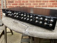
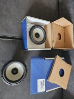
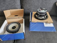
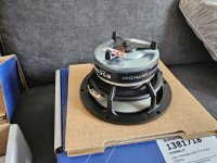
Lab instruments _ analog vs digital

Hi sorry for the maybe infantile kind question
Being in love with lab testing at some point in the future I would like to start my own measurements
At present I have a question
Let's take a signal generator or a scope as examples
The main offer is of digital units
Still on YouTube I see many experts using old analog generators and scopes etc.
My guess is that they are somewhat obsolete ?
If I am right why people are still using them?

My guess however it's been proven wrong at least in one case
A totl Audio Precision analyzer has a analogue sine generator slightly less in THD plus noise than the digital one. It has both options
At present I see two options viable for amateurs
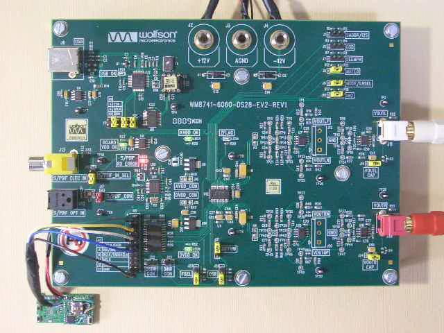
A standalone Signal generator plus USB audio ADC like the e1a ADC or a complete USB audio analyzer like the wonderful qa403
Any advice/suggestion will be very welcome and much appreciated
Thank you very much to All of you
Have a nice day
Gino

WD25TEx

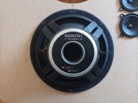
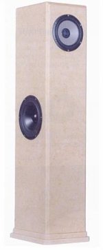
My speakers are these Peter Comeau towers. Loosely described as "aperiodics" brecause they were originally inspired by the Dynaco A25 but inside a sealed box/bubble consisting basically of two compartments, both sealed to the exterior with a communicating "aperiodic port between them. So presumably any woofer movements are limited first by compression of the air in compartment 1, thanks to to the "stiff" port and then also by the resistance to be compressed of thevolume of air in the 2nd compartment.
I have no desire to understand what´s happening but in practise the woofers are virtually motionless (1mm at most) during all sorts of music beit Reggae or symphonic so how can it produce any bass at all ?
Just wondering if a 2nd resistive port say in the base of the towers could help the bass go lower.

Question 2 : Given its importance Is there a practical way to check that my towers are indeed sealed around the drivers - I used draught excluder to make up my gaskets for the drivers. Should I reinforce these with a sealant of any sort ?

Noisy USB outlet? Request for testing help.

Hello! I know this isnt exactly related to audio design. But I do hear a high pitched sound coming from my outlets.

I recently remodeled a home and upgraded to USB style 115v outlet receptacles.

However now I hear a faint high pitched hum in the house. My thoughts are that inferior parts are causing "noisy" outlets.

Also the faceplace color and outlet color was noticeably different, both are labeled as white and they both came in the same package. This is just a visual annoyance and not an issue.

So in the spirit of finding a quality USB outlet. I purchased about 9 samples from Amazon.

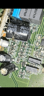
I removed the 4 screws from the back of the receptacle to expose the insides. However I have no idea what I'm looking at from there. Some are noticeably more complicated than others.

Anyone here interested in testing these? A simple Google sheet would be helpful in finding the true winner.

The goal is to test basic functionality of the unit. (Rated Voltage, Actual Voltage, EMF Emittance, General Quality Of Parts Used, Functionality with two USB devices plugged in, If device is emitting high pitched noises)

Please let me know if you are interested! I can mail these unit and we can test!


Thank you

Attachments

  • IMG_2426.jpg
    IMG_2426.jpg
    121.7 KB · Views: 72

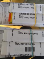
For Sale Toshiba 2SA970BL/2SC2240BL

I have for sale 100 pairs of 2SA970BL / 2SC 2240BL.

Min 10 pairs.

2SA970BL I can sell separately. Price is dependent on numbers. Please enquire with your needs.

2SA/2SC - $5/ pair. Shipping at cost.

R

Attachments

  • IMG_0951.jpeg
    IMG_0951.jpeg
    405.1 KB · Views: 92
  • IMG_0952.jpeg
    IMG_0952.jpeg
    649.7 KB · Views: 89
  • IMG_0955.jpeg
    IMG_0955.jpeg
    235.6 KB · Views: 71
  • IMG_0954.jpeg
    IMG_0954.jpeg
    239.3 KB · Views: 76
  • IMG_0953.jpeg
    IMG_0953.jpeg
    393.3 KB · Views: 77
  • IMG_0956.jpeg
    IMG_0956.jpeg
    283.9 KB · Views: 100

The Chill-baffle3 speaker page

Hi Folks.

I just finalized a webpage to describe my latest three-way open baffle speaker, see:
https://www.fedde.nu/audio/chill-baffle3.html

Stereo.jpg


It uses an 15" daudio woofer, 6" 18 sounds 6ND430 mid driver and ESS AMT tweeter (aka "Heil AMT") with Harsch XO and Hypex Fusion 253 plate amps. More details on the webpage.

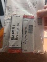
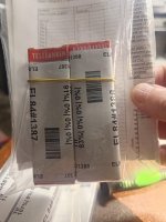
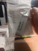
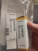
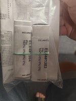
For Sale EL156 Telefunken (lot of 8)

[SOLD]

Hello,

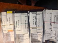
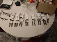
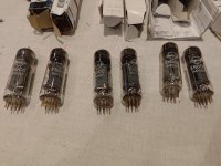
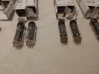
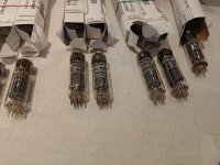
I have a lot of 6 EL156 Telefunken, 4 are NIB and 2 used (without the box). Scroll down for pics. Specifically:
  • a pair of NIB EL156 Telefunken, same production batch from 1981. Boxes in excellent condition. 350 EUR for the pair.
  • a pair of NIB EL156 Telefunken, close production batches from 1980. One box missing the flap. 250 EUR for the pair.
  • a pair of USED EL156 Telefunken. Serigraphy slight different between two samples. 75 EUR per unit.
Or… 600 EUR for the entire lot.

12 EUR shipping to Europe / 18 EUR shipping worldwide. All registered with tracking number.

I will accept returns within 15 days under the following 2 basic conditions: they come back in the same electrical and cosmetic condition as they were sent, and 2) shipping costs are not reimbursed.

Cheers!

[SOLD]

crossover phase and some more questions

Hello, dear friends!
I'm designing a crossover for an active speaker on a tda7294 chip. The frequency response and impedance curve completely suit me. However, I don't have enough knowledge to evaluate the phase. Please check it. Do I need to make any adjustments to the diagram?
And a few more questions:
1) Will a polypropylene capacitor of type X2 (snubber type) have advantages over a conventional mylar capacitor in position C4?
2) How much worse would it be to use 2 electrolytic capacitors, anode to anode, in position C3 compared to Mylar?
3) I can't figure out the resistor power dissipation graph in VituixCAD. With the "flat" option I need 5W. When estimating "m-noise" no more than 2W. What to choose?
Thank you very much!

Attachments

  • new_custom_2way Six-pack.png
    new_custom_2way Six-pack.png
    32.9 KB · Views: 92
  • new_custom_2way XO-schema-1.png
    new_custom_2way XO-schema-1.png
    6.2 KB · Views: 87
  • flat.png
    flat.png
    7.4 KB · Views: 83
  • m-noise.png
    m-noise.png
    5.3 KB · Views: 92

4 woofers crossover, is this sound?

I am working on a open baffle speaker with four 10" woofers. I want all four to play low and only one to dip into the upper bass. (I am sure there is a technical term for this). I couldn't find anything online after a long search....only examples with two or three drivers. I want 4 drivers series/parallel or parallel series.

I don't know a whole lot about crossovers but I managed to cook something up. If it could work I will order some parts and try it out.

Could this work? Is there a better solution?
1000000916.jpg


Also, C1 will be quite a high value...what kind of capacitor (possibly with a higher quality bypass cap) would work in this position?

Thanks

A new Line Source HT mains project begins!

Hey all. So got a request to do a custom build for a client/friend who just purchased an 85” flat screen to use as the center of thier combined living/media space. Their desire is for minimalism and symmetry and no center channel!!!…..other than that, I have free reign.

I would have gone in wall for sure until seeing the space and the wall is brick! So much for that! 💩

Well….on wall it will be and I’ve just finished some prelim and came up with a shallow on wall sealed line source for on either side of the screen.
We’ll use 10 Dayton ND 91’s for this 5 groups of two with each group wired in series and all 5 wired in parallel. For tweeters, we’ll use 20 of the Dayton ND20FB domes. I’m not sure how low I can go with 20 of these and not hit any audible distortion on dynamic peaks though…..ideally a 2k cross would nearly eliminate most lobing but only measuring will tell. Off axis response is as good as it gets out to 10k and with the ND woofers, I’m looking at a prelim of 80hz-12khz at flat out to +/-45 degrees so this ’might’ just work out for a phantom center system with just a wee bit of tow in….maybe a baffle angled inwards 5 degrees or so.

The plan is for these to butt up right against the edge of the screen so the screen will act as a continuation of the baffle reducing diffraction and aiding in baffle step. The little ND tweeters if placed inboard should handle the job……the needed low crossover for a true line source is the head ache….the distance between the woofers dictates a cross at no more than 2k to really sum up.

Sub woofage will be handled by an existing pair of Klipsch 12’s they already have placed in the two front corners and the Klipsch on wall surrounds will save……both the center and horn loaded Klipsch towers go bye bye along with the entertainment center the TV sits on……it will go to a wall mount.

So for those that see anything with the driver or design choices I’ve Made, feel free. Depth of the speaker is constrained to 5” which is equal to the TV profile mounted on the wall. Width?…..well….the minimalist thing kinda dictates the obvious……for visual balance, I’m thinking 8” wide max……that will give me enough internal volume sealed to hit a target F3 of 70hz and enough out board baffle to chamfer to meet the wall while minimalizing diffraction…..I hope.

Best woofer and tweeter for ATC SM75-150

Hi.
First post here. Not so new to DIY but new in the forum.
Already partially discussed but that was some long time ago and may need an update. I have purchased a pair of SM75-150, willing to pair with a woofer and tweeter. I am targeting around 100l. Will be built with minidsp, active crossover to 3 amps. Purifi for the woofer and 2x Sabaj a30a for mid and tweeter.
Design is ported.
Similar to a SMC100 ATC, a clone.

My candidates for the woofer are:
- ATC SB75-314 I can purchase from a dealer in Canada (fs 21Hz, Qts 0.24 and Vas of 360l)
- Scan Speak 32w/8878t01 (fs 19Hz, Qts 0.33 and Vas of 234l)

The Scan Speak is a little bit more expensive but is better on paper and can go lower in a 100l box. The ATC seems to be the original design but some say not so deep. The Scanspeak seems to be a beast and very very good woofer. ATC is also excellent I suppose.
Any recommendation?

On the tweeter, candidates are (with more or less integrated waveguide):
  • T25CF001 Seas excel, same as previously used by ATC. Can get a pair used.
  • Scanspeak D2905/990000 Revelator. Doesn't seem to be widely used. I don't see a lot of reviews but one of the few scanspeaks with waveguide.
Other good candidates? Morel?

Crossover points will be 380Hz and around 3000/3800Hz. Some say the mid can go up to 3800Hz, others say maximum 3000Hz. ATC goes up to 3800Hz.

I am interested in your feedback, recommendations. Thank you ! Louis

SEAS 27TFFC c/w Visaton WG148R Waveguide & Other Speaker Drivers

I have some NEW & used drivers for sale:

SOLD******2 NEW SEAS 27TFFC 1" Some Dome Tweeters (currently attached to the Waveguides below) ****SOLD

2 NEW 6" Visaton WG148R Waveguides - $39 USD per pair with Free Shipping

USED Drivers below:
2 Peerless (Vifa) 27TG35-06 1" Soft Dome Tweeters - $49 USD per pair
with Visaton WG-148R - $79 USD with Free Shipping


1 Mission "Super 770" - SEAS P21WO-11 8" Woofer - $25 USD for one
1 Mission "Argonaut 1F II" - SEAS P21WN-15 8" Woofer - $25 USD for one
1 Boston Acoustics 8" DVC (Sub) Woofer - $10 USD for one
2 Mission 770 Woofer Trim Rings - $5 USD for the pair

Take ALL above (NEW & USED) for $109 USD with FREE Shipping to Canada & US
Paypal in US & Canada and e-Transfer in Canada

Attachments

  • 20240605_224848.jpg
    20240605_224848.jpg
    682 KB · Views: 96
  • 1000006089.jpg
    1000006089.jpg
    822.9 KB · Views: 117
  • 1000006092.jpg
    1000006092.jpg
    909.8 KB · Views: 92
  • 1000006093.jpg
    1000006093.jpg
    1 MB · Views: 106
  • 1000006157.jpg
    1000006157.jpg
    695.9 KB · Views: 102
  • 1000006612.jpg
    1000006612.jpg
    745.6 KB · Views: 114
  • 1000006615.jpg
    1000006615.jpg
    654.6 KB · Views: 107
  • 1000006618.jpg
    1000006618.jpg
    682 KB · Views: 101
  • 1000006619.jpg
    1000006619.jpg
    715.2 KB · Views: 92
  • 1000006623.jpg
    1000006623.jpg
    462.1 KB · Views: 90

Improve a Yamaha amp THD by 12 dB!

And now for something completely different … referring to the 2015 … 2021 thread “Improve a Rotel amp THD by 20dB! “ and also referring to Monthy Python, of course.

Yamaha AX590 / AX592 / AX870 and AX890’s are not so bad amplifiers, but come along with some quite hefty flaws and quirks. E.g. there is no input pair’s degeneration. And amongst other, at first sight obscure twists, Yamaha has completely messed up the thermal design in all of these series with their’s smallish internal heatsinks and lowish idling current. Funny also to see how much space was internally wasted inside the bigger housings of the AX870/AX890: The “higher” model’s boxes are big not to contain better/more technical functionality, but only for prestige’s sake. Even the slightly bigger headsinks of the AX870/AX890 would neatly fit into the case of an AX590/592. The buyer just got a prime portion of a lot of air for her/his spent extra cash.

Just for interest, I gave the AX890 a slight twist on the Vbias trimmer, increasing the idle current of the power transistors to a theoretically more correct value. The Re’s are 0.22Ohm, and I increased Vre from much too low “Yamaha-standard” 5mV … 6mV to some theoretical correct value of approx. 26mV. This measure alone has a very decent effect on thd. So this might be a simple, effictient mod:

Measurements were taken with a sinewave signal of 1.5kHz, at 2Vrms out along with an 5Ohm output resistor. THD is 0.0074% at 6mV and 0.0018% at 26mV. The 3rd harmonic in both graphs seems to be a consequence of the non-degenerated input pair. At 6mV, there is a prominent spike of 2nd harmonic distortion, and also a smaller spike of 4th harmonic distortion. All other spikes above 1k5 are measuring artefacts.

Beware: This is a “hot mod”, as at +-60V and 2*120mA each heatsink has to deal with approx 25W … 30W while idling. So with it’s 2 channels, this glutton now draws hefty 60W while idling. I think that the addition of a big, slow rotating, silent ventilator like the one’s found in multimedia PC’s would be necessary to keep things cool enough inside a “productive” amplifier.

In listening tests the “hot” version appeared a wee bit more immersive than the “cool” version. But it is only, while notable, a slight difference. And also autosuggestions plays it’s role, as the test was not blinded.

After having blamed Yamaha in the intro: You may see it this way - Yamaha seems wisely to have chosen 5mV as a compromise value. To avoid the whole system from getting too hot. In this aim, some “poor” 25mA idling current for each output transistor pair might be a “sweet spot”. Because, on the other side, further reducing the idling current gives rise to a whole series of higher order (n=4 ...) harmonic distortions. So maybe, looking differently at it, Yamaha after all made a wise choice, at least an ecologically sane one. One of D.Self’s design is the “Trimodal Amplifier”, a switching Class A or B design, in which he jokingly suggests a switch labelling “Winter” and “Summer”. Winter for class A, Summer for Class B. The same might go for this kind of Vbe tweaking.

Attachments

  • 6mV.png
    6mV.png
    20.3 KB · Views: 366
  • 26mV.png
    26mV.png
    20.3 KB · Views: 361

Matti Otala - An Amplifier Milestone. Dead or Alive

hi

Lineup here.

We sometimes, quite often actually! mention
the name, papers & amplifier works of Matti Otala.

There are a few, very few, audio profiles that can become
a legend in their own lifetime.
We are fortunate to have some of those at this forum ....... 😉
Become a legend when you are dead and bueried, is much less difficult.

Anyway, this man Dr. Matti Otala from my neighbour
country of Suomi ( I live in Ruotsi http://fi.wikipedia.org/wiki/Ruotsi )
is actually still alive and working & thinking 😎
He has passed his 60th birthday, going for 70 now.
But this is not always a major drawback.
In fact, it is a nice thing to be able to get old & still be in good shape 😉

Me, Lineup, like to honor Matti, while he still may ba able to read my lines.
Here is a picture of this friendly looking man.
And some further links to his current whereabouts in internet.

An externally hosted image should be here but it was not working when we last tested it.


The birth of the Otala amplifier

On an AES conference in 1973, Dr. Matti Otala presented a paper describing the design of a TIM-free audio amplifier. Present at this conference was Svein Erik Børja, a Norwegian record and broadcasting producer, and a great audio enthusiast. Svein Erik Børja also was one of this times greatest Golden Ears. He was able to hear even the slightest imperfection in an audio component. Having been dissatisfied with the sound of that days transistorised audio amplifiers, he here saw an opportunity for getting an audio amplifier of a new generation. The talk of Dr. Otala about TIM also was an explanation to Svein Erik for the imperfections he himself had noted in audio amplifiers.

He brought the paper to a friend of him who was running his own audio company in Norway, Per Abrahamsen of Electrocompaniet. Per decided to make a try at the amplifier ........

HighTechForum Finland: http://www.hightechforum.fi/index.cfm?j=365834
Otala Family: http://www.otala.com/
Matti Otala, 60yrs, reception 28-Dec-1999: http://www.otala.com/webcast4.html


Regards, Lineup

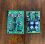
For Sale LM4766 4 channel diy amp

1715536139391.jpg

Hello for everyone,
I have recently developed this 4 channel module based on LM4766, in order to use for my self and to other diy people.
On this module, it's outputs are configurable as 4x50; 2x100; or 2x50 more 1x100 Watt making it suitable for Hifi stereo,
bi-amplified speaker system or multi-channel.All channel are free of noise "no hiss" very clear sound.
On the example pictures shows that with the optional trimmers which were applied on channel 3,4 the output offset
voltages can be adjusted near to zero, without trimmers on channel 1,2 the output offset voltage was around -4mV.
For more info you can also check this module on chip amp forum.
I have listed this module with both isolated and non isolated IC's at my page if you have interest you can check here:
https://www.ebay.de/usr/dialedinmusic?_trksid=p4429486.m3561.l2559

Attachments

  • 1702169290729.jpg
    1702169290729.jpg
    427.7 KB · Views: 71
  • IMG_20240511_153714.jpg
    IMG_20240511_153714.jpg
    514.1 KB · Views: 71
  • IMG_20240511_154507.jpg
    IMG_20240511_154507.jpg
    427.2 KB · Views: 84
  • 1710006254464.jpg
    1710006254464.jpg
    494.9 KB · Views: 81

Talk Electronics Storm 1 schematic

I have this amplifier which, believe it or not, I won in the UK magazine HiFi Choice competition they run every month when I was living there back in ´97... I've modded it in several stages, the last one a couple of years ago and, as I was tidying up my LTSpice circuits folder, I realised I'd never shared anything about it. Since there's very little info to be found out there other than the user manual, which I uploaded myself to HiFi Engine here, I thought I'd post at least the stock schematic in case any owners (if any left!) google for it. Note that the sensitivity, S/N and FR figures shown are simulated, not measured.

I've also attached a picture post-the last mod, I have some more detailed ones if anyone is interested (sorry, I didn't keep any before pictures). The little transformer and PCB at the bottom are a remote volume control kit from Dantimax, the small PCB on top of the main one is a 4th-order Butterworth high pass filter I put at the output of the phono preamp to get rid of a nasty 10Hz resonance in my cartridge and underneath it is where the discrete preamp used to be, which I removed and replaced by re-purposing the opamp that was the input buffer for the Tape 1 input. I also modded the phono preamp and the output stage. I can go into more details about the circuit and my mods if anyone is interested.

Cheers,
Cabirio

Attachments

  • Talk Storm 1 stock sch.png
    Talk Storm 1 stock sch.png
    65.6 KB · Views: 187
  • Talk Storm 1 mod.jpg
    Talk Storm 1 mod.jpg
    662 KB · Views: 191
  • Like
Reactions: huggygood

New Member from Germany

Hi, I am a Danish citizen living in Germany since 39 years.
I have been into HiFi since more that 45 years. Here a short list of my equipment:

  • Cambridge CXC DC drive
  • Audio Note DAC1
  • Audio Note M1-Phono preamp
  • 2 Audio Innovations S800 power Amps (by-amping)
  • Martin Logan Aerius (not i)
I have often looked at different tweeds here on the forum and decided to join.

Regards
Rino

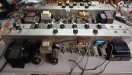
Do you recognize this (most likely Australian) vintage tube amplifier?

Do you recognize this (most likely Australian) vintage tube amplifier?
I found it on a Polish advertising website.
The front appears to be stereo, but when viewed from above, two identical output transformers are missing. The current owner has no idea what this design is or whether it works. The amplifier has a strange plug and we don't even know what the mains voltage is

Screenshot_2024-06-06-05-18-24-77_d4c83e98b7363fb18e9bde28130b0ba3.jpeg


Screenshot_2024-06-06-05-18-29-60_d4c83e98b7363fb18e9bde28130b0ba3.jpeg


Screenshot_2024-06-06-05-18-36-27_d4c83e98b7363fb18e9bde28130b0ba3.jpeg


Screenshot_2024-06-06-05-19-33-58_d4c83e98b7363fb18e9bde28130b0ba3.jpeg


Screenshot_2024-06-06-05-19-45-50_d4c83e98b7363fb18e9bde28130b0ba3.jpeg

Bose 1801 bias runaway (solved)

This ancient 35 kg monster amp came back after a repair involving several blown transistors in the output stage including Q4. Now this is a V(be) multiplier that has an unusual high voltage of 3.5 V across it. I had replaced it with a 2N2219A from my tray only to have the owner complain about the right side getting blistering hot and finally cutting out due to the thermal sensor. Sure enough, bias current went through the roof with even a small load (3 W). See my notes:
00.jpg

While the V(be) multiplier did its job it clearly wasn't sufficient. I set up a test jig and compared the few TO-5 transistors left in my tray:
01.jpg

Only a NOS 2N3444 with long legs, even more vintage than the amp itself (1968) seemed to have a better response. When I swapped it out the bias behaved as can be seen in the lower half of the page where I measured several V(be) voltages at different temperatures. I heated the heatsink with an external source (TO-3P power zener). When putting everything back it behaved nicely:
FLIR2001.jpg


The rectangle is a small black patch needed for the FLIR to measure the temperature of the bare metal.

The schematic is full of errors, this version has sorted most of 'em. Note that Q4 is marked "SIM" in the manual which means that it is specially selected. Well, this one certainly is!

I hope this is of use for someone.

Attachments

  • Like
Reactions: Thmartin

Mackie 1604-VLZ3 OL/Mute LED issue?

Hi,

I have the above mackie mixer that I'm trying to repair. It initially wouldn't power up at all and I found the rectifier on the PSU had died, replacing that seems to have got the power supply back up and running ok.

The issue I have now is that as soon as you power the unit up (with only the main board & PSU connected together), every channels red "OL/Mute" LED's are constantly lit and the "Rude Solo" LED is flashing. I've confirmed that the +/- 16v & +48v supply rails are all ok (even with the main board connected) but I just can't work out what could be causing this now...

Has anyone got any ideas or had experience of repairing these mixers before?

TIA

Quad 10" Subwoofer question

Hi all, i have built a quad 10" subwoofer for my home theatre room as an experiment as i sold my SVS downfiring years ago once i had kids, now getting back into movie watchin i thought i could make a decent sub for much less than a decent off the shelf sub.

SO what i have done is made a heavily braced box with 4 10" speakers (budget friendly) each speaker is powered by its own seperate amplification channel, so each is being fed its own personal 100watts. All of these amps are then connected to one main line to feed the sub out on my main amp so that each speaker is fed the exact same signal.

As these speakers are all closer than a 1/4 wavelength as its only used under 100hz that means i should be gaining +3db for every doubling of speakers. So 1 to 2 then 2 to 4 so effectively +6db correct? THEN i am also running my own individual 100watts to each speaker so that nets me another +3db for each doubling or is it for each individual speaker? This last part i am lost on.....am i gaining only +6db extra or +12db in this scenario then asding ontop the +6db from mutual coupling.

I would love a definitive +db answer as im looking at making another sub the same way.

Thanks for the help!

Attached a photo as everyone loves a photo.
IMG20240519172728.jpg

Folded horn recommendation

Looking for a speaker project. I will be driving with my 6LU8 compaction tube amp, a out 3-4 watts. I was thinking of frugelhorn,and then realized that I really did not want themin thecorners of mylistening room. With the tube amp, high efficiency is desired, I amcurrently driving 89dB sensitive speakers, either Advent graduates, or Polk Monitor 50s. Both sound pretty good, but ea h has it's owndrawba k, the Advents have great low-mid range sou d, the Polks are very neutral.

I was thinking 6" full range, with a folded horn like the Fostex design. I have e heard that their designs are not the best, but t have no idea why or what woudbe better.

Any positive feedback on the Fostex design, or a suggested alternative?

Roger

Syncronous motor speed drive power supply

Hy all, after a long time I 'm back to the forum.
I think what Im asking today is a common problem discussed tonns of times,anyway, I Just want to ask if there is a definitive Way to drive a sincronous ac motor, the classic premotec Many users have for their turntable project. My turntable runs very well and precise but I need little corrections somtimes,speed is supsceptible of spindle temperature humidity, belt age and all the common mechamic problems a turntable normally have. If you know a good way to point me would be fantastic.
The motor is frequency dependant, so I know is difficoult that someone has already developed agod project, but for sure if there is any way to do it I will like always I will found the right informations here

Greetings from Lithuania

Hi,

Listen to music probably for 8 hours per day or so for many years now.

Only recently got into proper gear in both headphones and speakers systems.

Well, recently I burned right channel on my Tandberg 3026A power Amp and am looking to repair or create a whole nother amp from what I have there already using TO-3 lateral MOSFETs. Loved the sound of it despite limited experience. And bad cabling within the amp.

I'm also building a two way speaker from JBL S580 trying to integrate the L100 Classic series titanium tweeters since Ioved how they sounded.

So I'm pretty new to all this.. but

I'll get there eventually.
  • Like
Reactions: krivium

I2S Making a cable with HDMI and RJ45 male plugs

Hello. I have an Audio gd Di-20 Acusilicon interface which has an HDMI I2s socket I want to use in I2S with my Sonnet Morpheus dac which has a I2S input but in RJ45. I plan to make a cable with a HDMI male on one side and a RJ45 male on the other side
On the Sonnet Morpheous RJ45 input card, there’s DATA, LRCLK, MLCK, SCLK but there’s no DATA-, LRCLK-, MLCK-, SCLK-
Does it means I only use DATA+, LRCLK+, MLCK+, SCLK +from the DI-20 and I don’t need DATA-, LRCLK-, MLCK-, SCLK- which are on the DI-20?
Thanks

Attachments

USB Headphone AMP DAC upgrade

Hello,

I built an USB-C Headphone Amp which works quite nicely (based on this tutorial: Phil's Lab #101). The IC (I used TI PCM2902 insted of PCM2900 in the video for SPDIF in/out) is not the newest model and the integrated DAC maybe not the best, so I wanted to do an upgrade here.
I could use the PCM2902 as a bridge USB-->SPDIF and I also want to connect a streamer with SPDIF (optical) out (probably Wiim mini to use with Tidal connect).
So I am looking for an IC with either direct SPDIF input or I need to do conversion to I2S in between. Are there any recommendations for ICs which are available at the common distributors (Mouser, Digikey) and best case there were already used in some projects where I could build upon? 🙂 Because of course I know the integration is at least as important as a nice measuring chip, so for me it would be great if there is more to find than only the datasheet.

For the input I have seen these ICs/devices multiplet times here at the forum:
S/PDIF to I2S:

-DIR9001
-CS8416

USB to I2S:
-"i2soverusb" board
-"amanero" board
(both quite expensive but would allow highres. Or would it also be possible to use the Atmel Controller on my PCB and flash it with some available firmware?)

also there is an amanero (clone?) with integrated S/PDIF)

I would do the layout with KiCAD and and order already soldered boards, so SMD is not a problem.
Do you have any recommendation in which direction to go?
Thank you very much in advance!

Best regards
Florian

Lab Gruppen C 28:4

Hi,

I got a hold on Lab Gruppen C 28:4 (old stock cleanup, was sitting in the corner forgotten). The amp was never used, in original packaging, brand new. The spec looks wild and TBH to me it looks like a little bit too much for home use. 🤷‍♂️

I think back in the day retail price was about 4-5k USD.

What do you guys think, what would be today's selling price as it was never used and still in original packaging?

Thanks! Cheers!

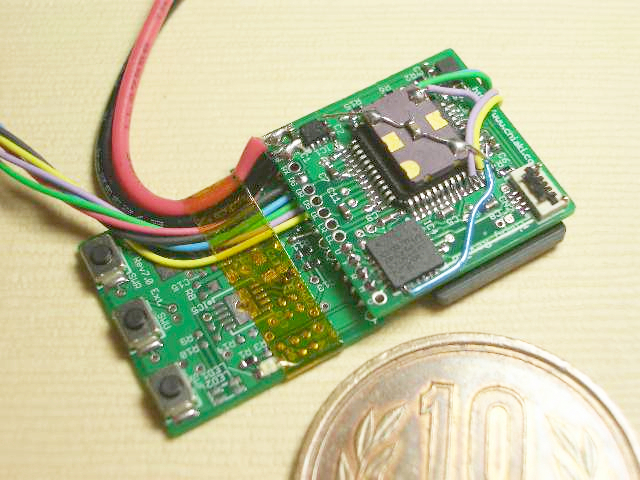
My DIY Soundcard interface for measurement aka' SuperRanger

So it's been some year's since i started my journey into the soundcard as a measurement interface etc...

I'm not expecting that someone is interested in this, but I would offcause publish both gerbers and the Arduino code if someone would like to see that.
- Nothing is secret... I just want to show my creating and have comment's and stuff on it?
There is no doubt that the outputcard could be even better as is, but the last -140dB noise/THD I cannot get rid of, but for sure I'm proud of what I archived.
I did get a lot of inspiration around the net, taking the best and most understandable parts... I'm absolutely no prof. into this.

When I found the thread here Behringer for measurement, @MagicBus warned me 😵 that the stuff was addictive, it sure was/is, but what a learning experience for me, thanks.
When I finished my hacked Behringer, witch is a mod with an OPA1632 balanced input card, some autoranger and stuff come to my mind, and I decided to try diy one myself, as at that time there was none availible at the market, lucky me for that.

I now have an useful one here on my desk, two years after, and many many hours reading and testing. - Not saying it's done, there will always be room for improvements.
Well... I figured out, that I would properly not hit the right card the first time, so I decided to make a "Motherboard" which should contain slots for the outputcard, the MCU ESP32 Devkit 1, the attenuator circuit with protection etc...

The current outputcard is balanced out only, so I needed a differential probe designed by @alfredr (Which is btw. very kind to help me out)
The probe is very good, giving me nice measurements.

What it can do or more like what my intention is, but I do think it's working pretty good now ::

  • Outputvoltage (target) can be set somewhere between 0.5Vrms and approx. 8Vrms.
  • The attenuator part can be adjusted in software to proberly fit the target e.g. when shifting to -6dB from -0dB could be done from around 1Vrms to 6Vrms.
- So soundcard accepting say 1Vrms or 4.5Vrms or whatever etc... can be used.
  • It can take more than 70Vrms with the correct inputcapacitor of cause.
  • Attenuatorsteps 0dB, 6dB, 12dB, 18dB, 24dB, 30dB, 36dB and 42dB. The Input impedance should be around 20k. Thank's to this Site
  • With the outputcard I use now, there are 64gain steps (0db to approx 25dB or so).
  • Clipping detection, input overload warning etc... in the software, along with information on the little oled screen.
  • Easy to choose between SE input or Balanced input.
  • Choose between manuel or autoranging.
  • Proberly I forgot something...

The autoranger function is not the fastest, (but sure fast it is), but now REW have the possibility to add a delay when using such autorangers, between measurement's when doing e.g. stepped sine, so it's working very good I think.

Here I tried sweeping from 1 to 35Vrms (Not using REW on this one) -- (Don't mind the minor glitches, some of them are duo to my SignalGenerator).
* Soundcard will allway's be within it's best range, at least it was my intention 🙂
SRSuperSweep.png

The gainpart (the output card) of the SuperRanger add's some distortion on it's own. (Picture FFT1)
When I tested it with my hacked Behringer soundcard, it look's like the SuperRanger is not adding anything, therefore I decided to upgrade my soundcard to one of the Cosmos ADCiso's, as I read that they are very good.
The yellow trace is where the SuperRangers own distortion can be seen when using the Cosmos ADCiso.
It's the outputcard witch adds this distortion.
As can be seen below on Picture FFT2, where I took a shoot of the attenuator output on the Motherboard, the Motherboard, attenuator part is more or less clean.

FFT1 ::
Victors SuperRanger compare.jpg


FFT2:
Victors to SuperRanger attenuator output to Cosmos.jpg


MB2.png
Outputcard.png

PSU.png


Here is the current outputcard used :
IMG_7240.jpg
IMG_7241.jpg


And some pictures of the whole setup, prototyping, testing etc...
IMG_6735.jpg
IMG_6780.jpg


This is an older picture, the PSU is different now, with some better regulators (Seen on schematics of cause)
The Motherboard without output card plugged in ::
IMG_6674.jpg


Last one just a showoff one sry... 😎
IMG_7310.jpg

Attachments

  • IMG_6781.jpg
    IMG_6781.jpg
    476 KB · Views: 134

Goldmund GM27 clone

Hi
I have just bought a Goldmund GM27 clone working on one channel only.
Does anyone know this specific PCB?
I cannot find any schematics for it, although I have plenty for other variants of this amp.

What I was curious about was the two power input sections at the bottom of the PCB. Why is only one of them connected? Is it just an alternative input?

Thanks for any help!

🙂 morten

Attachments

  • GM27_01_1920.jpg
    GM27_01_1920.jpg
    740.5 KB · Views: 317
  • Like
Reactions: ginetto61

WTB UTC S-30 swinging choke

Looking for a second UTC S-30 to complete a pair. However if someone has multiples, and the price is right I would be interested.

Also looking for a few much more obscure UTC bits for completing a stereo pair, from US military com gear... there is a 5-digit designation, Ive never been able to find any list or catalog of these things... I'm not imagining I'm actually gonna nab one of these, but one can dream... more like a "check ebay twice a week for 7 years" kinda thing but...

UTC "68571" plate and filament (630vct)
UTC "71432" tube output (5k pri)
UTC "63832" choke

No TF.......YY typical military designation on those, so, can't match other manufacturers...

Acquired NOS & boxed, not pulls, so I don't even know what units they came from.

Papa’s slot loaded open baffle version #2

With sometime on my hands, I decided to try a pair of Papa’s slot loaded open baffle speakers. Not the large ones with the multiple woofers, just the simple ones that came later, with one woofer each.

I had a local woodworker follow Papa’s plans. I rounded up some nos Fostex FE 206En for the full range and Augie 15’s for the woofers.

Poking around on the internet, I found Dick Olsher’s site (Blackdahlia.com) had plans for an open baffle (OB3) that used the Augie 15’s and listed crossover specs for his final version. He had his full range crossed over at 250hz, second order and the woofer at 80hz, first order with reversed polarity.

I haven’t built my crossover, yet. I had an old SAE 4000 second order crossover that I rebuilt a few years ago. I dusted it off and set the FR to 200-250hz and the woofer to 80-100hz, with reversed polarity. Not bad at all! I’m on my first week of listening and my first pair of speakers built, ever. F4 for the full range and an old Hafler P500 mosfet for the Augies.

I’m thinking a low cost active crossover as my next purchase. It might be nice to be able to adjust the orders and values separately and see how things sound. I’m learning a bunch and usually puzzled at some point. But then I read a bit more on a new thread and it slowly comes together.

As always a big thanks to Papa! And to ZM, 6L6, MJ, Dennis and Pico who are always guiding, assisting and got me through my F4 build.

Wishing I’d be getting on a plane to SFO for BA2020. Maybe next year.

Attachments

  • 881A5C8E-F719-4861-8604-548BBC01BE04.jpg
    881A5C8E-F719-4861-8604-548BBC01BE04.jpg
    872.1 KB · Views: 4,234
  • 31BDD783-A295-493A-AD3B-0A7AC0D7EAB7.jpg
    31BDD783-A295-493A-AD3B-0A7AC0D7EAB7.jpg
    837.4 KB · Views: 4,211

AC output coupling capacitor for a low power amplifier

Hi all,
I built a little single supply 5 Watt amp (8 ohm) with the intention of boosting the power rails and using BTL to boost the power to ~40Watts. However the 5 Watts is plenty loud enough for where it's going to be used so I'm going to leave it. Presently I'm using Rubycon 63PK3300MEFC18X40 63V 3.3mF output capacitors and the results sound good with thunderous bass.

According to the internet, output caps should cause distortion but the number of data points is limited. Ie from Douglas Self's site a 6.8mf causes lots of distortion when driving at 40 Watts but a 100mF is OK. Does anybody have any info on what the happens when driving at low power? Does having a 63V capacitor with a 24V power supply improve/make worse the distortion levels?

Thanks...

Pearl3 project made me purchase a TT and a new rack!

New TT and rack system arrived!
TT was last one and only available in walnut!
I got it a bit cheaper and accepted that!
I also got 2M Black LVB cartridge mounted for no extra money (original the TT came with an Audio-Technica MM).
My current rack was not stable enough for a TT and a wall mounted shelf does not fit well in how everything is setup in my living room.
It is a 4-shelf rack with TT on top. The empty shelf is for Pearl3. Next shelf below is for DAC, Streamer etc. and lowest shelf is for PSU's (not in picture).
HiFi furniture's can cost a fortune but this one was very reasonable (will call it cheap for the quality). Net. weight 52 kg with 4 x 15mm tempered glass shelves.
54 kg total in one box was heavy to pickup at the local HiFi shop!
TT is approx. 18 kg and it was transported all assembled back in my car from central Copenhagen as cartridge and everything was assembled and adjusted.

I can blame P3 for that!

Attachments

  • DSC_4312.JPG
    DSC_4312.JPG
    263.4 KB · Views: 502
  • DSC_4315.JPG
    DSC_4315.JPG
    166.2 KB · Views: 484
  • DSC_4316.JPG
    DSC_4316.JPG
    82.9 KB · Views: 524

For Sale XOno 2019 by RStAudio

SOLD
I have for sale a Pass DIY XOno Phono clone (2 boards). Build with good quality components (matched Toshiba semiconductors). Matched/measured WIMA RIAA capacitors.

Including two power supply boards with recommended transformer with 4 x 32.5V / 1.0A + 10V / 1.5A made by Rondo is of high quality. The power transformer primary only support 230 V AC operation.

Board have been soldered. Commissioning need to be performed.

Boards by Ralph Stens, RStAudio.de. Documentation included on CD made by Ralph.

Also a RStAudio AC/DC filter board is included.

Shipping within the EU is preferred. The price does not include PayPal and shipping costs. Only shipping with insurance and tracking. Shipping within EU approx. 24 EUR.

Price excluding shipping and PayPal fee is 400,- EUR.

Offers are welcome

Attachments

  • Xono_1.JPG
    Xono_1.JPG
    862.5 KB · Views: 165
  • Xono_2.JPG
    Xono_2.JPG
    1 MB · Views: 159
  • Xono_3.JPG
    Xono_3.JPG
    861.3 KB · Views: 133
  • Xono_4.JPG
    Xono_4.JPG
    846.2 KB · Views: 122
  • Xono_5.JPG
    Xono_5.JPG
    758.9 KB · Views: 127
  • Xono_6.JPG
    Xono_6.JPG
    368.9 KB · Views: 153

Emphaser EA2500D schematics/component number

Hi there guys,

Does anybody have schematics from this amplifier?
Does anybody know the component number from QP6 and RP5?

QP6 and RP5 are missing. Seems like these are supplying the VCC to the TL494.
Amp is dead except for the final stage output relais powering on? (Weird)

Attachments

  • 20240525_201518.jpg
    20240525_201518.jpg
    615.5 KB · Views: 82
  • 20240525_201530.jpg
    20240525_201530.jpg
    702.2 KB · Views: 83

Fosi V3 Review on Open Baffle Speaker

Fosi V3 Review

So why try a Fosi V3 when my studio has a full active Paradigm Reference 5.1 system and I also have a Denon receiver for project power? Well there were two reasons, the first being all the positive reviews from diverse users regarding a small factor class D amp and secondly, I am designing a 3d printed turntable and want a very compact system for demo days.

The amp has been put into service powering a dsp controlled open baffle speaker I created from drivers I had lying around the studio. The portable requirement and open baffle was a perfect fit and enter the Fosi! The speaker is an unholy match up of a Celestion 12" Seventy 80 16 ohm guitar speaker and a 1990s Radio Shack 4" 4 ohm coaxial car speaker mounted to a piece of 3/4" plywood. On first power up the whole thing almost ended up in the bin, but..once the dsp crossover and eq was applied, it came to life. Driving an open baffle with a 12" driver is no small task to keep the excursion controlled and tight but the wee amp is doing the job extremely well! It is also using the stock power supply and at normal listening levels, transients and details are excellent.

The combo of the open baffle and the Fosi produce sound, especially for acoustic pop and jazz, that is surreal! It is almost like the artist is in the room with you. This effect of open baffle dipole speakers is well documented but being able to do it with a cost effective amp the size of a paperback and some leftover speakers is in fact a game changer.

I normally work with large systems from Meyer and L Acoustics and such and using DSP is a given, but bringing this tech down to numbers individuals can afford is what we have here. The system will be tuned and a second speaker will be built (this test was in mono) as well as another Fosi V3 will be added to create my demo rig to show of the turntable.

I have to thank Jerry from Fosi for sending me this lovely little beast to test and I am truly happy to have seen something very different and useful!

BTW, the Fosi sounds much better than the old Denom AV receiver.

Pros
•Compact size
•Very smooth sound for a class D amp
•Adequate power from supplied power supply for conservative listening levels
•Handles large drivers in an open baffle speaker very nicely
•Price!

Cons
•binding posts very close together
•small power supply as standard

Login to view embedded media

Attachments

  • 20231218_153743.jpg
    20231218_153743.jpg
    162.6 KB · Views: 130
  • 20231218_153752.jpg
    20231218_153752.jpg
    295.7 KB · Views: 115
  • 20231218_153755.jpg
    20231218_153755.jpg
    265.1 KB · Views: 131
  • 20231218_153802.jpg
    20231218_153802.jpg
    270.4 KB · Views: 127
  • 20231218_153838.jpg
    20231218_153838.jpg
    414.9 KB · Views: 129
  • 20231218_153845.jpg
    20231218_153845.jpg
    324.3 KB · Views: 129
  • 20231218_153848.jpg
    20231218_153848.jpg
    285 KB · Views: 127

Update on my 3 way open baffle project (w. AMT)

Hi all,

It has been a long time (2-3 years) that I discussed my first steps to design an open baffle loudspeaker utilising a Mundorf AMT and an acoustic elegance Dipole woofer.
(old thread: https://www.diyaudio.com/community/...ng-bass-driver-and-u-frame-side-wings.384160/)

I made some progress on this project in the meantime but also could not really work on it due to several reasons (private and professional).
Now that things have settled I am back to it!

A quick summary on the current stage of the project:

Drivers are set:
  • Mundorf AMT23D6.1-R
  • Audio Technology C-Quenze 18H52
  • Acoustic Elegance Dipole12
I have set up two prototypes (with the configuration in the old post).
I came to the realization that the crossover topic would delay this project significantly as I have never done this before and I did not want to go through the unavoidable simulation + trial and error for optimizations rounds.
So I decided to make them active with Hypex Fusion FA123 plate amps (with included actrive crossover). IMHO an ideal combination!

Next step: To optimize driver placement and test a revised prototype (I have measurement equipment & use REW).
Goal: to make it as small as possible without sacrificing design & performance.

The version 2 looks like this (without the nice frontplate and without the waveguide for the AMT):

The design is now made with FreeCad and fully parmaterized so that I can easily change settings and driver placements.
I already "converted" one of my prototpyes to these dimensions, the next one will be slightly taller and narrower.

I will post some measurements in the next days and hope you can give me some advice on how to optimize it.


Open Baffle V2.png

Hello from Atlanta!

Hello from Atlanta! Audio is my hobby as a result of my avocation of music performance- I play trombone in big bands and have done so since college, almost 50 years.

My gear is as follows:
Oracle Delphi TT w/EY2 arm and Panasonic strain gauge cartridge (for which I'm seeking a modern, sonically superior pe-pre to replace the original Precision Fidelity unit);
Philips AH-6731 black AM-FM, recently refreshed;
BAT CD (tube);
BAT pre (also tube);
Sunfire load invariant 600-2 2 ch amp (600W@8/1200W@4 & 2400W@2);
SoundLab Aura electrostatics

I'm looking for info on upgrades and replacement parts ,and to deepen my knowledge.
Thanks!

Increasing size of coupling cap in this phono circuit

I did some reading on increasing the size of a coupling cap, and it seems to be that it’s really circuit dependent. I have this pho preamp, and these caps are the last in the circuit which connected to the rest of the preamp.

IMG_0980.jpeg

The two I’m specifically talking about are C415 and C416. They are 0.47 uF mylar or maybe polyester. I have some Panasonic polypropylene in that value, but I’m wondering what effect it would have if I increased the size. 0.68? 1?

I have some pretty nice quality polypropylene when I get into the 1 microfarad and above range. Out of curiosity, how high could I go? Could I put 2.2 in and see a benefit in the audio? or should I stay lower closer to the 1 microfarad? Or should I stick with 0.47?

Dan

G'day DIY-ers

Hi Everyone!

I'm a long-time DJ and more recent Mechanical Engineering student. The latter is a bit of grind in my late-thirties, but bit-by-bit, we're getting through it.

Making some speakers is on the cards and something I think about way too much. I'm hoping with all the signals-processing maths they're cramming down my throat, I'll be able to build something nice one of these years.

I'm reasonably handy with a soldering iron, one of my jobs is assembling through-hole PCBs. I don't know much about electronics though. About I'll I know is "Inductors will bite me" and what capacitor does.

My home set-up is pretty humble.
For the Amp, I've got a Technics component amp (SU-Z11, SH-8015 EQ).
The speakers are some nice, home-make units (not of my doing) with RS-150-4 and Vifa BC25SC55-04. They measure 3.5Ohm across the terminals, which I'm guessing translates to 4Ohm inpedence, not that I know what impedence is.
For the Turnie, SL-1200 with a ortofon OM cart and Nightclub MkII stylus.

I love the asthetics of the technics amp, but is probably the weakpoint in my set-up. I recently found a Sanyo DCA-200, which I was hoping would give me a bit better fidelity. My dumb *** purchased untested and sure enough, the Left channel is putting out nothing but hum. I've found a thread suggesting what transistors to use in replacement, assuming it's the source Mosfets causing the issue.

I also have a old Yamaha monitor I'd like to refoam. Got the replacement foam, just need to have a crack at it.

Anyway. Thanks for having me. Look forward to chatting soon.

Barry.

Technics SE9600 please identify these parts

Hi guys. A couple of days ago I received a Technics SE-9600 power amp. Someone applied new thermal paste to the power transistors on the heatsinks (which is not a bad idea) and mixed up the positions of each transistor (very bad idea...).
Now I have to resurrect the amp.
I'm having trouble finding a replacement for the following part:
D510: RVD10D1 the manual only says "meter detector"...
Could anyone tell what type of diode this is? And what replacement I can use?
I'm pretty sure there are more hard to find parts in this amp...

For Sale Transformer spring cleaning

Cleaning out the shelves and selling some transformers:

1x pair Output transformers : 5W, 50ma, prim 4k5, sec 4 - 500 - 1000 / could work as OPT for a poweramp or preamp. SOLD


1x pair Tim Wood interstage transformers (HK ebay seller from back in the day) : 1+1:1+1, not much other info left, they were advertised for tubes like 6SN7s etc, so I assume 10-20ma gap. 50€/pair

1x pair Tim Wood Step-up/down transformers : prim 0-30-ct-350-600 / sec 10k-0-10k (no info about dc gap) 50€/pair

Will ship worldwide

Attachments

  • IMG_3939.jpeg
    IMG_3939.jpeg
    352.6 KB · Views: 154
  • IMG_3940.jpeg
    IMG_3940.jpeg
    349.4 KB · Views: 142
  • tempImage3ICpnE.gif
    tempImage3ICpnE.gif
    1.4 MB · Views: 300

Class D

I have had the opportunity to live with a few Class D amps, various NAD including the Purifi Master Series and a boutique brand that eludes me, I think they went back to A/B. Of course class D amps can have excellent bass and a really low noise floor, but perhaps they are too clean for me, a little 2nd order never hurt anyone. I have not been won over to the D side as I find the midrange not as engaging, 2nd order(?). A friend has asked me about the Bel Canto, just wondering if anyone has had a chance to audition 1?

Advice on single rail supply phono preamp design

This is my first post, so any advice, including "Go search better in the forum," is accepted.
I need a simple phono preamp to upgrade a Philips home system made in mid '70s. It has a cheap vinyl record player on top with a crystal pickup, and I decided to replace it with one from the same era having an MM pickup instead. It's nothing fancy, but I need a working preamp for a pretty average system. I have found this old thread here, where this design was suggested:

Screenshot 2020-11-25 at 11.32.55.png
The construction seems to be straightforward. However, as I will need a double rail power supply, I will have to add another transformer because the original system (while also using op-amps) does not have two rails but just a single 15V supply. The tread included the suggestion to change the design for a single supply:
phonopre modified.JPG
I first modeled the schematic in LTSpice, and the result of the simulation was OK. Then, I implemented the design in hardware, and it did not work. Interestingly, when I replaced the op amp with LM386, it kind of worked, but with one of the chips. The other, very identical chip from the same batch did not work. All the op amps I have tried are functional. One of the problems that I have found is the 330uF capacitor charging slowly, as there is a significant potential difference between the ground and the inverted input in the modified version. The original schematic does not imply the significant static difference in the potential between the signal ground and the inverted input, so the problem should not have happened there. As the current through the capacitor is rather small, the potential at its positive terminal stays low for a long time, significantly lower than that of the non-inverted input. This may be the main reason why the opamp does not work.
So I need advice on how the design could be modified to make it work properly from a single rail supply.

DamFilterDesigner App : create and display FIR&IIR Lowpass Filters for Soekris dam

This app was aleardy introduced in the Filter Brewing for soekris dam thread, but it's time to open a dedicated thread, so here it is.

This app is made with MATLAB app designer an is free of charge.
I am an electrical engineering student from Germany and this app was developed while procrastinating studying for exams ........

This app is for designing FIR and IIR Lowpass Filters for Soekris dam1xxx (in next release also dam2xxx)
The type of Filter, wether it's an interpolation Filter, an decimation Filter (for DSD) or just Lowpass(IIR) is selected automatically.

Currecntly you can design FIR Lowpass Filters with the following techniques:
  1. Spectral Windows (Standard windows like Kaiser, Hann, Blackman-Harris... and Albrecht 3-11th term, and Albrecht Minimal Side Lobes)
  2. Halfband linear and minimum phase
  3. Nyquist linear and minimum phase
  4. least Squrare
  5. ParksMcClellan
  6. Equiripple linear and minimum phase
  7. LeastPthNorm mixed and minimum phase
IIR design:
  1. Butterworth
  2. Chebychev
  3. Elliptical
  4. Quasilinphase
The IIR Filters can be higher order as they will be converted to cascaded Biquad Filters.

You can verify the designed filters right away with:
  1. Magnitude Response
  2. Phase Response
  3. Impulse response
  4. Step response
  5. Group delay
  6. Magnitude Response Estimate only valid for dam1xxx at the moment
The Magnitude Response estimate is working with fixed point arythmetic:
Coefficientsdatatype:
  • 1.31 for FIR1
  • 2.30 for FIR2
  • 3.29 for IIR
productDataType:
  • 35.35
AccumulatorDataType:
  • 4.24
Output Datatype:
  • 2.30 for FIR1 as these will go into FIR2...
  • 2.30 for IIR as these will go into FIR2...
  • 2.26 for FIR2 as we have a 28bit ladder dac
I found this a very important feature as this serves as an overflow detection.

About Gain:
  • standard gain is applied to the corresponding Interpolation Rate
  • When designing Filters you can chnage the Gain in form of a Correction Faktor:
    eg. the FIR1 Filters designed by Soeren have a gain of 8 and an correction factor of 0.7585
    if you multiply these you get the 6.8 gain value you can find in the filter text files...
  • DSD Filters have a gain of 30dB - this comes from: 24dB gain in the DAC and 6dB gain because it's dsd...
    but again you can make a gain correction by the factor
  • I strongly advise to have a look at the magnitude response estimate and change the correction faktor so the filter wont overflow! This is especially the case when designing Filers with short Coeff length as their values are simply higher.

The designed filters can be stored to a list inside the app that does all the sorting for you.
In this "Filter List" the filters are shown with their properties:
  • Filter type FIR1/FIR2.. ,
  • Filter Bank F4/F5/F6/F7..
  • key values (like attenuation at 20kHz)
  • Input Sampling Rate
From this list you can select a matching pair of FIR1 and FIR2 filters and plot a cascaded mangitude response!
The magnitude response estimate however does not work for caseded filters...

Next feature is the import of .skr filter Files:
You can import ANY .skr filter file, no matter how old, plot the responses and add them to your "filter list".
This way you can import your favourite old filters and mix and match them with new ones.

Of course you can export the designed Filters as a .skr file!

As filter design is not done in a day you can save your "filter list" as a matlab workspace (.mat) file that can be opend up later to resume your work.

The newest feature (but not properly tested so kind of beta) is Upload of filters to dam:

As this is not a commercial tool and I'm not a pro this tool is not free of bugs, so please report any problems and I'll try to correct them

At the moment I'm trying to integrate an automated Room Correction feature but that is difficult...

You can download the App here:

https://jp-hoffmann.de/Files/DamFilterDesigner2_3.zip

Be aware, this app is pretty big and quite Power Hungry as it is running MATLAB Runtime in background.
From users aleardy testing the app I got the sense that you need Win11 or Win10 at least, not sure.

Enjoy

Here are some example pictures of how the app looks like:
app_1.png


app_2.png

Hello from Germany/Ulm

I am falling in love with digital&analog electronic awa uC SW development for decades. I have a professional background into this areas.
I like it to read source code and schematics from interesting projects to learn from and to improve.
All the time I have running a couple of HW/SW projects which never come to an end, unfortunate!
I am impressed/keen on open source, networking around the globe and community power to realize projects.
  • Like
Reactions: krivium

  • Locked
Wave Energy - The Best Solution

I've been a long time critic and opponent of wind turbines. They are extremely ugly to took at destroying otherwise peaceful views of their surroundings, and they are noisy to their neighbors. But the worst part is that they kill more than 573,000 innocent creatures each year in the United States including eagles, hawks, falcons, owls and other birds. For the rather small amount of energy they produce, about 10% of the total in the US, they are not worth all the problems and destruction they cause.

On the other hand I've been a big advocate of wave and tide energy as the best solutions possible.

Now here is the announcement of a highly successful wave energy program. This technology can be continued to grow in scale with no downsided to our animal friends and hopefully we can begin to tear down the all of the ugly and destructive wind turbines.

https://www.msn.com/en-us/money/markets/turning-ocean-waves-into-clean-energy/vi-BB1jbvP3

For Sale First Watt M2Clone w/ pick up in Punta Gorda, FL

First Watt M2 Clone for sale and pickup in Punta Gorda, Florida. I believe I built this amp sometime in 2017, but it has been upgraded a few times since. I sold (traded) this to a friend and he has since moved from Michigan to Florida. The boards, output transistors, and Edcor’s are from diyAudio member Tea Bag and included Harris 9240’s which don’t exhibit the IR “bloom”. I don’t recall Tea Bag offering JFET’s, so they would have come from a batch of matched Toshiba pairs I purchased from member Spencer years ago. As I recall JFet’s were in the 7-7.5 range. The blue caps you see pictured (C2) are ClarityCap PX series, other parts are Vishay RN-60 resistors, Panisonic ER 3W resisters (scource resistors), and Wima film caps. Chassis a Hi-Fi 2000 5U/400 Disipante chassis w/UMS pattern giving lots of room to maneuver inside and the option of “cranking” the bias if other FW clone boards are installed. IEC receptacle /Fuse holder/ power switch by Shurter, Antek AS-4218 toriod. DiyAudio power supply upgraded to 8 Nichicon 22,000 uF (don’t recall what series). I wire everthing with Faston 110 spade connectors which I like for making quick changes (no desoldering) of other FW clone boards. Installed is a H9KPXG low voltage On-Off switch drives AC mains relay \ includes soft start and momentary ring lit push button switch. Binding posts and RCA’s are by Cardas. I did upgrades/preventive maintenance a couple years back and everything is in tip top condition. The amp is configured a little different than most being that the tranny is mounted in the back and amp boards are flipped left to right, this gives very little transformer interference (even with no shielding on the Edcor) and the amp is very quiet…I want to say dead quite the last time I listened to it, but not 100% certain. Also has Jensen JT-11P-1 input isolation transformers installed to prevent ground loops.

Asking $1000. PM me if interested and I will put you in touch with Tom in Punt Gorda.


imagejpeg_0.jpgimagejpeg_2.jpgimagejpeg_1.jpgimagejpeg_0 2.jpg

Am I interpreting this information correctly? (Tweeter selection problem)

I have an old pair of PSB Image 2B speakers I use on a mini stereo system out at my cabin. I did an upgrade on them by replacing the cheap electrolytic caps in the crossovers with some higher quality Dayton 5% audio-grade caps. The result was very noticeable and pleasing.

The tweeters on the 2Bs were made by Peerless and you can get very similar Peerless tweeters that will bolt right in from Parts Express and other places quite inexpensively. You might also still be able to get the "official replacement" tweeter from PSB (haven't checked to see if they're still carrying them) but I've heard they're 3 - 4 times as expensive as the replacement tweeters from PE. I don't want to put a lot more money into these speakers so I won't buy the OEM ones if they are even available but I'm willing to pay the $22 each to get a replacement from PE.

The Image 2Bs have a nominal impedance of 6 ohms (which I know doesn't mean much) and a minimum impedance of 4 ohms. The crossover frequency is 2.5 KHz.

There are two tweeter models available from PE that will bolt right in and there are 4 and 8 ohm versions of them both. I'm only interested in the highest quality model of the two models so that would be the Peerless BC25SC08 model. The question is, should I get the 4 ohm or 8 ohm version?

Here is the impedance curve for the Image 2Bs:

impedance.gif


I am definitely no expert here but the way I figure it, when you get to say 5 KHz and above pretty much all of the impedance you're seeing is from the tweeter. Is that correct? And that impedance looks to be around 8 ohms. Correct? Where the speaker's impedance curve drops below 6 Ohm is down in the low frequencies where it's all woofer so my interpretation of that is it's the woofer that's driving the 4 ohm minimum impedance rating, not the tweeter. Is that correct?

Here are the impedance curves for the 8 ohm and then 4 ohm versions of the BC25SC08 tweeters/

BC25SC08-08
An externally hosted image should be here but it was not working when we last tested it.


BC25SC08-04
An externally hosted image should be here but it was not working when we last tested it.


Based on these three plots, I'm thinking the PSB OEM tweeter was an 8 ohm rated tweeter so the BC25SC08-08 is the correct one to replace it with.

Is my interpretation of the data correct?

Trouble sourcing Anthology II parts in EU

I'm having issues sourcing the tube used for mid drivers. It's a pipe with inner diameter if 6 inches and outer diameter of 6 5/8 inches. It's quite damn thick! Didn't manage to find anything like it in croatia. The closest is 15 cm and 16 cm tubes that are nowhere as close as thick as that. They around 1/3 of the thickness. Here is the speaker document link.

https://www.speakerdesignworks.com/anthology.

I was thinking about perhaps making the Statement II instead, but then the mid drivers were nowhere to be found. Any idea where to get NE123W in EU?

About to take flight in plane... Brb. It'd be dope if i got some answers when i land

Tnx
Byeee

PSB Image tweeter repair

I just finished doing a writeup of how to repair PSB Image tweeters. I haven't found any information on the internet on this topic, but there is floating around many recommendations for a third party tweeter which I do not think is a great match. In the hope that this information is useful to someone I'll leave a link to my blog/whatever:
PSB Image tweeter repair guide
  • Like
Reactions: wyup

Help with old Mission 770

Hi everybody

I have a chance to get a pair of old Mission 770.
I'm not sure about a few things and would appreciate any help.
I haven't heard that particular set yet and have not seen them in person.
I want to check first if it makes sense to drive 3 hours to check them out in person. 🙂

1.) There seem to be scratches or discoloring on the bass. See the first picture. Is that an issue? Or signs that it got hit or something?

2.) The owner does not know what version and from when exactly they are. But the handwritten serial number looks like it is from a really early stage.

3.) Does Mission 770 of that age need any major overhaul after all that time? Crossover, Caps, ...?

4.) What would a pair of those be worth right now? Because the price seems a tiny tiny bit higher than what I see others go in the US for.

5.) Can I drive those with an Elekit TU-820R or is that a bit on the lower side?

Thanks a lot and Happy weekend.

Tobias

Attachments

  • MISSION 770 - 1.png
    MISSION 770 - 1.png
    402.9 KB · Views: 196
  • MISSION 770 -2.png
    MISSION 770 -2.png
    277.1 KB · Views: 164

Adcom GFA-545 with high DC offset

I have a GFA-545 (original, not the II) that has a large DC offset on the left channel. I've followed the service guide and biased it to 6.5mw on the test points, but am currently seeing 700mv at the terminals. I've pulled the left channel board and am powering it via two bench supplies, with no difference in behavior. All of the transistors test out and seem to be in spec. I've tested each of the emitter resistors, and they are also in spec. If I feed the amp a since wave, it will drive an 8ohm load to a bit over 100w per side before clipping, and looks clean. No difference between L and R.

Where should I go from here?

Cyrus One versus Cyrus Two

I have now two units. Cyrus One v.TOG and Cyrus Two v.07. Soundwise these are very different. Cyrus Two has significantly more treble, almost too bright and somewhat fatiguing and bass could be better pronounced. One has beautiful clean and soft bass, but highs are dull and lacking - no spark.
Is this normal for these units or cap replacement has affected the sound?

C One has only 470uf ROE caps replaced(by me), C Two has full cap work done(by previous owner).

F2 and F2J pcbs

F2 / F2J Clone PCBs

Hi,
I have a pair of F2J pcb( separate left and right channels) and CRC power supply board for sale. Buyer has to pay for shipping and paypal fees.Please remember these boards are long 28cm.
These boards can handle boutique caps for output and inputs as there is provision for connecting capacitors with unusual dimensions( need to be outside the board). Standard caps on board are for polystyrene and poly-prop.
A mouser component list will be send with boards.
Both amp PCB have holes drilled for fitting 4U heatsink from DIYaudio store.
Power supply board has mouthing holes matching pre drilled plate from DIYaudio store.
Power supply boards can connect with 120V/240v supplies with dual primary winding of transformers as used in Firstwatt designs.
Update 1/2/19
The second run of the boards is closed for meeting target. limited to 10 set of boards. Please add your name to waitlist from now on! Will give you preference on cancellation.
They are now UMS boards, that can be easily mounted in a UMS heatsink from DIY audio store.

Attachments

  • image.jpg
    image.jpg
    618.5 KB · Views: 1,528
  • image1.jpg
    image1.jpg
    722.7 KB · Views: 1,472
  • image2.jpg
    image2.jpg
    510.8 KB · Views: 1,443
  • image3.jpg
    image3.jpg
    670.3 KB · Views: 1,393
  • image4.jpg
    image4.jpg
    670.3 KB · Views: 1,364
  • image5.jpg
    image5.jpg
    587.9 KB · Views: 509
  • Like
Reactions: Paulo Batista Gomes
Projects by fanatics, for fanatics
Get answers and advice for everyone wanting to learn the art of audio.
Join the Community
507,687
Members
7,884,285
Messages

Filter

Forum Statistics

Threads
406,038
Messages
7,884,285
Members
507,687
Latest member
sarah xenran