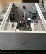
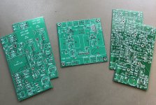
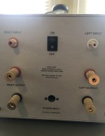
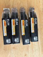
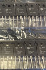
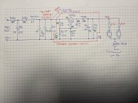
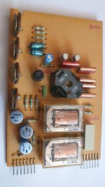
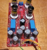
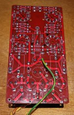
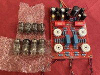
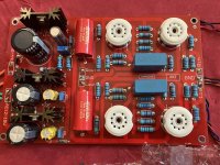
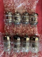
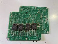
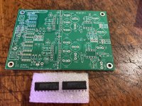
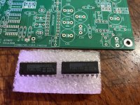
2020 DIY Sony P-Channel VFET lottery amp #044

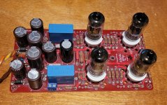
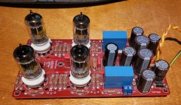
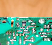
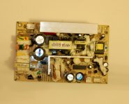
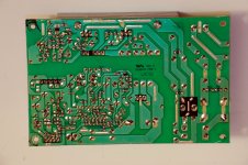
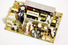
I have decided to let my original / first run single-ended Class A VFET lottery amp go to an established fellow diyAudio member that will give it the proper attention and use it deserves. Very little time on this one, maybe two weeks and has sat on a shelf ever since. Carefully and expertly assembled by a dedicated longtime diy'er with IPC J-STD and A-610 certifications. This unit is built and functions exactly as designed and intended. Amp is completely stock, but will include an optional PS board and a couple of transconductance (current output) amplifier front end PCB's designed by Mark J. that I didn't get around to trying out. Price is SOLD + PP G&S fee + actual shipping due to inflation and just the rarity / keepsake / collector nature of this fine amplifier. US sales only. I will pack carefully and ship with UPS, tracking information provided. Thanks for looking.

Attachments

  • IMG_0260.jpg
    IMG_0260.jpg
    414 KB · Views: 134
  • IMG_0262.jpg
    IMG_0262.jpg
    403.3 KB · Views: 138
  • IMG_0345.jpeg
    IMG_0345.jpeg
    667.4 KB · Views: 132
  • IMG_0346.jpeg
    IMG_0346.jpeg
    269.8 KB · Views: 147
  • Like
Reactions: ItsAllInMyHead

Front speaker location options

My car has only 4” x 6” speaker holes on the dash for front speakers, yellow arrow. However, there are 6” holes on front door for factory audio upgraded option, red circle. Mine has only speakers on the dash.

IMG_8600.jpeg


I have a pair of 5 1/4” component speakers. I’d like to use it for my front speakers. But as said, the front speaker holes are limited for 4” x 6” size and cannot be installed the 5 1/4” speakers—the magnet will stick to the a/c vents inside the dash.

I wonder whether I should drill the front door cards to install the 5 1/4” woofers in the red circle and put the 1” tweeters on the dash, yellow arrow. OR, I should buy a new pair of 4” speakers, either coaxial or component, to install on the dash at one point.

For Sale 10 x Line array waveguides simlar to B&C ME102

I purchased these waveguides for this project: https://www.diyaudio.com/community/threads/constant-curvature-tweeter-array.388439/#post-7275853
but they don't workwith extension horns in a tightly curved array so they are now surplus to requirments. I will accept any offer which covers postage from the UK to where you are! you have to buy all 10 as I'm clearing out things for a move.

Source for genuine TDA1543s

Hi,
after i heard a 16xTDA1543 DAC I would like to build one myself, but most of the ebay suppliers are a bit strange. The chips they sell all have the same number on them. Are these relabeled fake chips or what is going on there ?
Do you know perhaps where to buy genuine TDA1543s or TDA1545s ? I like the idea to use them in parallel and avoid a complex output stage.

Bass frequency issues regarding bass. Speakers are TL/Ported?

Hello everyone its Bazza.
So an add on to previous thread, about the bass. Iv done a low frequency test from 25hz to 150hz amd this is what I got. Up to 49hz nothing 50hz it begins up to 75hz. From 75hz to 120hz ish flattens out onwards to 150hz.
What I don't get is this, songs that I know produce the hi pressure in the gut type bass I should get...but...I don't! I get instead a vibration a heavy type, can feel it on the floor the sofa everywhere! !. I don't understand? During the sweep 25hz to 50hz I got no vibration, from 50 to 75hz good good bass no issues with vibration it wss solid.
Please guys n gals helpe me out

Constant voltage PSU

Hi boys,

I am working on my pp class A amplifier. I am currently working on PSU of the Driver stage (my amp have only driver and power stages). The driver is formed as LTP using CCS in the cathodes. I found out that i need constant voltage supply for driver. Fluctuating voltage in the power supply network +-10% would greatly affect the operating point of the driver.
The picture shows the whole situation. In the red frame is the voltage "regulator" that I designed. Unfortunately, I am not a friend of simulation. What do you think, can it work well? Of course, I take into account that zener diodes are not very accurate and have a thermal coefficient, but that is nothing compared to the +-10% fluctuation of power networks. I also know about a large amount of zener diodes noise, but it should be cancelled in the differential pair of power stage. The driver differential pair has a constant current draw, so I don't have to worry about voltage regulation.
What do you think of my circuit? Would you change anything?

Thank you

Jan

Attachments

  • Constant voltage PSU.jpg
    Constant voltage PSU.jpg
    399.4 KB · Views: 149

New ADSP21489 4in/8out board with front panel and ES9028

Hello,
I recently bought this card on Aliexpress: https://www.aliexpress.us/item/3256805054463128.html

WhatsApp Image 2024-02-18 at 12.19.01.jpeg


which should be the most updated version of the card in this thread:
https://www.diyaudio.com/community/threads/cheap-adsp21489-4in-6out-pcm1798-board.339777/


The software that the seller provided me has serious problems, it is not possible to insert the exact values in the Gain and Q parameters because by moving the mouse from the input box or simply passing the mouse arrow over the input box, the value changes randomly, setting maximum or minimum values
I've attached some videos that shows the issue

The software installed is named DP48X control software (version 1.8)
On LCD display is also possible to view the firmware version:
WhatsApp Image 2024-02-18 at 12.19.34.jpeg


The boad sounds very well and it's possible to connect Amanero card directly, but the control software works very bad, so is impossible to set corret values

Someone bought this card with the same ploblems and solved the issues?

Regards
Francesco

Attachments

  • EQ issue.mp4
    5.8 MB
  • GAIN issue.mp4
    2.1 MB

gas competition 7000.1

i a few month ago tried repairing this amp, i have since then made progress and found the problem.

square wave at power stage mosfets leg are fine without mosfets in and with them in the square wave will not come down to ground propertly. ive checked the pulldown resistors which are 1 10k ohm resistor per 6 mosfets, when replacing the pulldown resistor with a bigger 1k ohm resistor the square wave is now present with one mosfet and after installing mosfets one after the other the square wave gradually dissappears. gate square wave on buffers are present all the time. buffers where originally c2814 but where replaced by bd237 but did not make any difference. any thoughts?

Soft start circuit design and other psu issues

I do not see how the soft start circuit can be made into a slow charge for a large capacitor bank in a high powered class A amp, as either the load on switching is VERY high, or the dissipation in the bypass resistors is very high. without the class A load, it is no problem, with the load, it is extreme. I think one would have to also switch the load after a duration..... which means more relays....

If any interest, I can post an LTspice sim using inductors for transformers.....

DIY-Speakers placed high up – downward angled baffle or driver(s)?

For our kitchen area, I'm planning to construct some compact 2-way speakers (17 cm wide x 25 cm tall) and integrating them nicely with a wardrobe.

The wardrobe ends currently at a height of 2,25 meters, which means both drivers will be considerably above ear level (given this is a kitchen, one would mostly stand upright). Speakers will be about 2 meters apart from another, listening distance will be anywhere from 1-3 meters.

What I am really pondering about (and couldn't find easily information on):
  • is it advisable to construct an angled baffle to have drivers fire downwards?
  • will it be worthwhile to place the tweeter below he woofer?
  • before committing to a design, would you advise me to make some experiments/conduct any measurements first (I suspect so) ?

The build doesn't have the ambition to be audiophile at all (it will be first for practical listening, great sound is plus!), but please do let me know your advice if tilting will be worthwhile to look into.

Keen to hear your thoughts! And thanks upfront

I have a confession to make

A minor or a major sin? You decide.
Using a garage sale box and some bits from the shed to make a new set of party speakers.
Going though my spare parts and trying to figure out a crossover to go with the hodgepodge of drivers I'll be using I couldn't make a decision.
Went on eBay this AM and found some Jaycar 3-Way crossovers from about 20 years ago [ 2004 catalogue says $57- each 200 watts and frequency divides to suit the old Tandy 2" dome at 1500 and 5k-.
It's a junk box why not use a junk XO? So I bought 2.
Near enough good enough?
I will need to put a zobel on the woofer but that's from stuff in the junk box and I finally get to re-use the old Tandy dome
  • Like
Reactions: kevinkr

SPDIF cable to connect a usb-to-spdif converter to DAC (no USB)

Both ends of the converter (converter link) and the DAC (DAC link) (this is just a sample image of another DAC but the COAX input seems to be same/similar for all DACs) - seems to be using RCA female sockets.

I can get the 75ohm RG6 cable of various brands (Belden/Canare)/etc) but I'm unsure of the connectors to use. Would normal RCA connectors suit (with/without modifications)?

Thanks

Tuned Sound Amplifier/Receiver for the VLF Christmas Eve transmission from SAQ, Grimeton, Sweden

The only remaining working Alexanderson Alternator is transmitting again this Christmas Eve from SAQ Grimeton, Sweden (near Gothenburg city) on 17.2 KHz. (congratulations to Sweden for preserving and operating the Alexanderson Alternator).

I would like to receive and record this transmission here in Cardiff, Wales. The Alexanderson Alternator generates the 17.2 KHz carrier with a power level of 200 MegaWatt. At that frequency (in the audio spectrum) and at that power, propagation is likely to be global (subject to signal to noise constraints).

I'm building a simple receiver feeding into a preamp plugged into my Laptop PC that is running a sound recorder program. So far I have wound a 35 turn coil using many-stranded Litz wire onto a long ferrite rod and plan to resonate this at 17.2 KHz with a good quality capacitor. Then feed into a preamp built with a second tuned circuit. Simply then connect to the Laptop PC using 3.5mm Jack plug.

Can anyone advise me as to the best way to build this simple receiver? For instance will the ferrite rod be enough of an antenna or should I connect to a long wire? Will a preamp with effectively two tuned circuits likely provide enough gain? And so on....

During my reading I understand that a problem with VLF reception is signal to noise, there are several unavoidable noise sources such as global lightning storms.

Any kind of comment gratefully received.
  • Like
Reactions: Aridace

Apogee AE-12A can work in 2024?

Guys,
There is a pair of Apogees AE12A's cabinets that are offered to me , looks like they are dual 18's .

The price looks reasonable for the cabinets only, I mean worst case scenario (busted drivers)

Good scenario: they will kick for some more years

There is a special on 2 drivers right now
LaVoce SAF184.01 - 8 149bux
And
Beyma 18WRS600 - 8 159bux

Does any of those will work on the Apogees?

Or I need something like 18TBX100

Found this specs in the net
Enclosure type: rectangular, optimally vented bass
Format: Electronically-coupled
Driver complement: dual apogee dd1803, 18" cone
Nominal impedance, 8 ohms each driver
Frequency response: 30hz - 105 hz +/-3 db, 1 meter on axis
Sound pressure level: 128db continuous, 134 db peak @ 1 meter
Max power handling: 1200 watts continuous, 4800 watts peak (600/2400 each driver)
Input connectors: neutrik nl4mp speakon
Rigging hardware: 12 guage steel nutplates on both ends backed with steel reinforcing brackets. accepts 3/8-16 threaded fasteners.
Dimensions: 44.75"W x 30"H x 22.5" d
Weight: 85 lbs.
  • Like
Reactions: Booger weldz

Measure secondary voltage with a digital multimeter

Hello
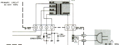
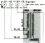
I have a power transformer that works out of 120V and I would like to find out the secondary voltage that this transformer brings out.
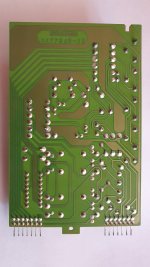
As you can see on the attached pictures, the left side shows four wires and the right side shows one pair, which is 120VAC. What (pairs of) wires from the left side carry the secondary voltage?
Thanks

Attachments

  • pic1.png
    pic1.png
    47.1 KB · Views: 71
  • pic2.png
    pic2.png
    17.5 KB · Views: 64

Hello all!

Hi everyone.

My name is Colin, and I'm interested in "trying" to make my own record deck and speakers. I have access to Rohacell foam so I am hoping to try and thermoform the cones from this material and use it to make an ultra lightweight record deck like the planar 10. I have been able to figure out how to get Rohacell as thin as 0.8 mm and I am aiming to hit 0.5 mm (not for speaker cones, a different project)

So, hi !
  • Like
Reactions: stv

Bi-wire speakers on a Hitachi HA7700

I have a Hitachi HA7700 integrated and a pair of speakers that can be bi-wired. The integrated has a speaker selector switch for A , B and A+B.
Can I take two pair of speaker cables wire one pair to the A speakers terminals on the HA7700, another pair to B speakers terminals on the HA7700 then put the speaker switch in the A+B position? Will this cause any problems to my speakers or the HA7700? The speakers are expensive and dont want to put them in danger.
The reason I have to do it this way is the speaker terminals on the HA7700 are not big enough for two wires. Barely big enough for 16awg wire.

Help with double chamfer

Hello everyone,

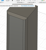
I am building a 3 way enclosure and I have a design idea I would like to implement. However..... I haven't figured out how to do it
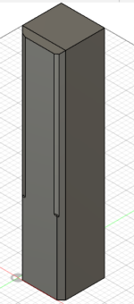
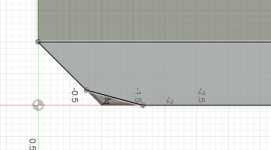
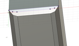
Have a look at my pictures. Basically I want an outer 45 degree chamfer and then an inner 15 degree chamfer on a 3/4" birch plywood enclosure.

The 45 is easy enough with a 45 degree chamfer router bit.

I am unsure of how to get the second 15 degree cut.

Any ideas?

I have a router (hand held) and a table saw (not a good one and I don't really trust it for precision angle cuts)

Attachments

  • Screenshot 2024-06-26 195411.png
    Screenshot 2024-06-26 195411.png
    24.7 KB · Views: 62
  • Screenshot 2024-06-26 195429.png
    Screenshot 2024-06-26 195429.png
    33.1 KB · Views: 66
  • Screenshot 2024-06-26 200024.png
    Screenshot 2024-06-26 200024.png
    14.2 KB · Views: 70
  • Screenshot 2024-06-26 200148.png
    Screenshot 2024-06-26 200148.png
    38.9 KB · Views: 65

TThechnology TT2500.1 protect flashes fast

so protect flashes very fast (5 per/s and wants to build squarewave for power supply mosfets. the initial state i bought it in was blown power supply mosfets and buffers, blown output mosfets. blown trace from coil winding. everything is identical parts exept for buffers those where replaced from l6 m6 to bc846b and bc856b. everything seem to check out on the tl494 and ive tried replacing that one to.

without power supply mosfets it checks out fine with squarewave.
it builds both rail voltage to 65v. could my dc power supply be insufficent for the power surge needed for the initial startup so it glitches?
any tips i can have?

Duelund silver foil capacitor 'autopsy'

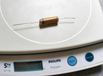
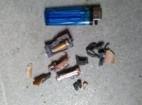
I opened a Duelund capacitor, so you don't have to do that 🙂 I thought that Duelund capacitors are physically bigger than Jupiter Silver Foil -Vitamin-Q because they have more foil and are better quality, but I was wrong. I found a ton of epoxy instead. The manufacturer could fit to 15mm diam package as 0.01uF, But for some reason he did't. I wonder what the real size of 0.01uF.. Overall these are great capacitors, I have no complaints about the sound quality

Attachments

  • duelund silver foil real size.jpg
    duelund silver foil real size.jpg
    501.6 KB · Views: 935
  • duelund silver foil 0.022 opening.jpg
    duelund silver foil 0.022 opening.jpg
    440.2 KB · Views: 883
  • duelund silver foil 0.022  junk.jpg
    duelund silver foil 0.022 junk.jpg
    256.3 KB · Views: 825
  • duelund silver foil 0.022 total silver.jpg
    duelund silver foil 0.022 total silver.jpg
    211.9 KB · Views: 776
  • duelund silver foil 0.022.jpg
    duelund silver foil 0.022.jpg
    425.7 KB · Views: 792

Rega Saturn I Laser replacement

My son's Rega Saturn has quit reading and thus obviously playing CD's. I am planing to replace the laser mechanism when I visit him but would like to replace the whole transport/laser system. The only replacement I can find is on AliExpress and it doesn't say which Rega player it works for. I believe someone said it is actually a Sanyo transport/laser. Can anyone tell me if the laser assembly is basically identical for the original Rega Apollo's and Saturn's? Otherwise what else I might check. The internet seems to show that the Saturn has problems reading certain CD's but mine has never had a problem and his started to glitch a little and finally won't initialize the CD when inserted. Thanks you in advance for any help you can offer.

For Sale Universal Power Supply PCB for TO 220 Voltage Regulators

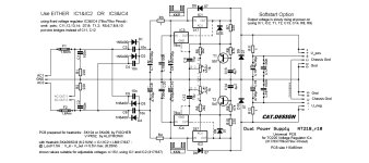
For lower power projects like preamps, headphone amps, etc. I like to use power supplies with TO220 voltage regulators.
I designed a universal board for this.
To power a recently built OREAD, among other things, I had some new supply boards made and now have some spare boards for sale.
The board can be used with TO220 voltage regulators like LM317/337 and 78xx/79xx or others with the same pinout.
It also allows the use of: fuses, RC-snubbers for transformer secondary windings, rectifiers like 1N54xx for full 1.5A current, CRC filtering, suitable heatsink,
soft start for output voltage.

The circuit below shows values for +/-15 volts output. A BOM (example/proposal) will be sent to buyers via email.

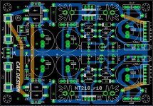
NT218_r10.jpg NT218_r10cu.jpg

NT218_r10pcb.jpg

Price for one Board: 5,80€
shipping inside EU: 9€ (I ship worldwide if you don't mind the shipping costs)

If interested: Email/PM me

Tannoy Mercury Mk2 - crossover upgrade

Hi all,

I've recently acuired some Tannoy Mercury Mk2 speakers - which (imo) look great, but are in need of some work.

The crossover seems quite basic and I've had a go at drawing it out - but surprised at the lack of capacitor in the woofer circuit?
Does this seem odd or is this how 80's speakers were designed?

I've measure the resistors (3.3 & 10) , the capacitor has measurements marked on it (6.8ohm 100v) and asked someone to measure the inductors for me (as I don't have the skills/tools!).

Here are some of the specs and images of the crossover below:

Peak power - 120 watts
Impedance - 8 ohms
Sensitivity Domestic - 93dB
Sensitivity Anechoic - 90dB
Frequency response +- 3dB nominal - 52Hz - 23Hz
Phase response - Better than +-45 between 120Hz-10kHz
Crossover frequency - 3kHz
Crossover type - First order low pass, second order high pass hard wired low loss

Colours in the diagram correspond to the photos (lower resistor is 10ohn, upper is 3.3)
xover.png


resistors are hidden under some glue so marked them:

xover1.jpg


xover3.jpg


xover2.jpg

Attachments

  • xover1.jpg
    xover1.jpg
    228.5 KB · Views: 88

efficient SPL tops DIY

hi
i am going to build 4x jbell ss15 tapped horn subs with the box 15lb075 drivers

but i need some tops too 😀

i want as efficient and loud drivers as possible while keeping it in the affordable range. sound quality is not my priority even though it would be nice too

i already got some stuff laying around:

2x spaudio tw-35s tweeters: https://www.spaudio.it/products/sptw-35s-150-watt-rms

1x Monacor SPA-112 PA: https://en.toutlehautparleur.com/speaker-monacor-spa-112pa-8-ohm-12-28-inch.html

1x Monacor SP-12A/302PA: https://en.toutlehautparleur.com/speaker-monacor-sp-12a-302pa-8-ohm-12-32-inch.html

this is what i got laying around.

should i build something with this or get something else?

is there some horn box that i can build for midrange speakers?

18Sound NSD1095N - As good as it gets?

My current speakers are pretty good, but I want them to be as good as they can be. Right now, I have B&C DE250s running down to about 1kHz on 18Sound XT120 horns. Below that, there's a couple of Seas H1252-08 (8" midbass units, hard aluminium cones). I'm aware that running a 1" driver down to 1kHz on that horn is asking quite a lot, but my listening levels are pretty sensible and I haven't encountered any issues with distortion in the midrange - the woofers run out of excursion first.

The NSD1095N looks to be smoother and more extended in the upper treble than the DE250. There's also the high-tech motor and the fact that breakup modes are pushed out past 20kHz. It looks excellent.
I've looked at the datasheets from Faital Pro, BMS, B&C and other 18Sound products, and I can't find much else (except some very expensive Beryllium models) which tick the same boxes.

My question is this: is there anything better at a similar price?

Thanks in advance,
Chris

PS - I agree that the woofers could also do with being upgraded at some point, but I'm looking at tweeters for now.

Chinese crossover: Ningke filters?

I have just received a 4in 8out Chinese speaker manager with FIR and IIR filters.
Available IIR filters are Butterworth, Bessel and "NINGKE" all with slopes from 6 to 48 db.
Now, since there is no trace of such "Ningke" filter anywhere, not even over the internet, I assume it must be a bad translation or typo, despite I must admit the manual being in good English instead of the usual Chinglish.
Anyway I'm left wondering what the h... is this "Ningke" filter ??

Of all filter types I know, "Ningke" sounds vaguely similar to "Linkwitz", however I wonder if anybody has any idea what it really is.
Apparently all Chinese crossovers mention this "Ningke" filter in the specs, so I'm not supposed to be the only one with this problem.
I thought this was a typo in the item description but it's the same also in the manual.

bass reflex vs paraflex vs tapped horns?

Hey everyone,

I’m starting the process of designing and building a sound system for a venue which I’m opening - we’re a 400 capacity warehouse, mostly doing dance music of various genres (as we hire out to different promoters we’ll be having pretty much every sub genre, house, techno, bass, garage etc)

I’m starting with the subwoofers (we’ve got a pair of RCF tt25a II on mid/high duty for now) and having spent a while reading on the forums and facebook groups i’m a bit overwhelmed by the options in terms of designs, and was hoping to get some advice from the collective brains to point me in the right direction.

In terms of our priorities, transient response and extension down to say 35 hz are at the top. Size is not so much an issue since we won’t be moving them around. Maximum SPL / efficiency is also not a huge priority given our venue has a limited capacity anyway and we don’t plan on scaling up. Let’s pretend also that budget isn’t a big problem for now as I’m willing to save up in order to get the right sound. We haven’t purchased amps yet so will scale our amp power to the design we go for.

Given these parameters, my question is what sub design principle should I be looking at?

I’ve narrowed it down probably to either a TH, bass reflex or paraflex design. FLHs are probably a bit beyond my capacity as a woodworker, though if they’re absolutely the right option i would figure it out.

for BR, I’m looking at Scott Hinsons double 18 design - https://www.facebook.com/share/p/6ngWaXTJrFypcyMu/?

I’m thinking there’s a reason the double 18 has been a classic for ages and maybe it’s best to stick to something tried and true instead of going for something advanced? If it’s a matter of building more BR cabs and loading them with generous amounts of amp to get the right sound, is that a good strategy? For TH, I’m considering the Keystones, and for paraflex probably the C2E golden formular. I understand the more complex designs beat out the BR in terms of efficiency but is there any other benefit to them?

Any and all advice appreciated, and I’m happy to clarify with further info if needed. Thanks!
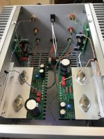
For Sale: Glassware Audio 12VAC Aikido Rev A. Built and tested for 12AU7

I am selling my built and tested 12VAC Aikido from glassware audio.
https://glass-ware.stores.turbify.net/aikido12vac.html
This is the Revision A version purchased in 2019.

Selling as I have run out of 12AU7's and my mortgage doesn't allow me to purchase more and keep building other things. Thus off this sought after piece goes.
I can provide:
-a pdf scan of the original documentation.
-the 4 CV4003 tubes, one of the right channel ones has gone noisy.
-the extra 20R and 47R 3w MOX resistors for tuning the heater voltage for your particular transformer.

I am asking USD100 + shipping.
I can also provide a 30VA 2x18vac. Configured for 230VAC operation. It could be reconfigured for 115VAC but the leads are short so it would not be easy.
Asking an extra USD15 for the transformer.

I can leave the ground and power leads installed or remove them.
Also I can remove the 5mm pitch screw terminals or leave them on.

Built using high quality parts throughout:
Vishay RN60 resistors except R16 which is an RN65
Wima MKP4 for C1 and C2
EPCOS/TDK polypropylene 2.2uF coupling caps.
Chemicon KYB series 10000 hour 105c caps for C4-C10
Rubycon TXW series 12000 hour 105c cap for C11
20240625_211948.jpg
20240625_211958.jpg
20240625_212009.jpg
20240625_212018.jpg
20240625_212238.jpg

Hi. I am from Thailand. It will be hard to pronounce my Thai name. So, please just call me Tony

I am new here. I started my speaker journey last month because I found my dad’s old Bose Acoustimass cubes, and was thinking about what to do with them. I just put them back in the storage after I did some reading here and found out they were not worth rebuilding. Anyway, that how it begin. It’s just hard to get out after reading so much about speaker. So, now I want to build my first DIY speaker. Nice to meet you all.
  • Like
Reactions: krivium

Recommend some 'audiophile' Bluetooth earbuds?

So I want some Bluetooth earbuds to use both with my phone and my stereo. Budget is 200 dollars max.

I did some shopping and there are 7,283,662,183 models currently available. Oof! If the braintrust here can at least point me to the good brand names I would much appreciate it. (the bad ones too!)

Also, is there a trusted review site for these?

Many thanks.

The SMPS HYS3C300 - No STBY + -7V identification element

Hello
HYS3C300 Power supply comes from an active subwoofer (Canton sub 600) and supplies power amplifier in class "D" and the preamplifier. I do not know the history of this failure and I do not know how the injury occurred.
With the power supply goes -7V symmetric + STB and power for the sake of power amplifiers (+ V GND) estimate of it is about 50V
The power supply will not boot no voltage + -7V output. I measured the bridge rectifier is checked 325VA DC fast diodes for the coincidence of the STB are working, t8 transistor (mosfet) to the original approx.
I'm stuck in a place because I have a problem with the identification of the part indicated by IC3 is 6 feet smd is written on it 32D06 if anyone knows what kind of system I would be grateful for information about him, visually no damage. What else should I check? Maybe someone has a diagram of a power supply with a similar topology that would have helped me a lot (If you have an oscilloscope available)
Adding photos PSU
Ps. I apologize for an error that says the translator

obrazki.elektroda.pl/9572795800_1423172062.jpg
obrazki.elektroda.pl/8381377400_1423172072.jpg
obrazki.elektroda.pl/5952004600_1423172066.jpg
obrazki.elektroda.pl/4775159400_1423172070.jpg

Attachments

  • 9572795800_1423172062.jpg
    9572795800_1423172062.jpg
    250.3 KB · Views: 1,361
  • 4775159400_1423172070.jpg
    4775159400_1423172070.jpg
    372.5 KB · Views: 1,261
  • 8381377400_1423172072.jpg
    8381377400_1423172072.jpg
    749.3 KB · Views: 1,319
  • 5952004600_1423172066.jpg
    5952004600_1423172066.jpg
    631.6 KB · Views: 1,436
  • 3536443600_1423172064.jpg
    3536443600_1423172064.jpg
    824.7 KB · Views: 1,156

First Class Amplifier Chassis 19inch 400mm 117mm

Here are the files for those with cnc, access to a cnc or workshop
  • 1.5mm base plate galvanized steel gauge 16
  • 4mm aluminum 6061/6063 front face anodized silver/black cnc
  • heatsink aluminum 6061/6063 anodized black mold or cnc
  • 1.2mm mild steel gauge 18 powder coated black all other parts
  • 19inch chassis 400mm depth, 117mm height
  • M4 screws self tapping top cover
  • M3 screws non self tapping all round
  • adjustable base plate , 10mm standoffs for transformer bolt

https://www.pcbway.com/project/shareproject/First_Class_Amplifier_chassis_99b8c1f5.html

Arcam Alpha 3 Tuner - No Power

Hello.

I recently purchased an Arcam Alpha 3 tuner. It was not powering on arrival so got a refund, but can’t bring myself to get rid of it!

When plugged in the power button does nothing, no lights or anything. I’ve checked the plug fuse and internal fuse, both fine. I checked the power switch is working with a multimeter and all good. I did notice the supercap (0.1F) has popped but understand that’s to store channel presets.

Any other ideas on checks or what could be the issue please?

Many thanks!

Port that is firing towards floor

I see many modern speakers with vented type installed their port underneath the cabinet firing down towards the floor. I just wonder is there a calculation for the gap between the port and the floor, does anyone know? I don’t think it’s simply a rule of thumb. I believe designing a speaker is science, not merely art. So, it should be able to be explained for any reason by Physics and Mathematics.

New to forum, just got first sub and amp installed: question about bottoming out

Hey y'all! So I got a cerwin vega hed 10 DVC in a sealed box and a nesa td-80 for an Amp installed on April 1st. I quickly found out I was bottoming out so I went back to the shop that installed it and upgraded to another cerwin vega, this time the VEGA 10", still in the same sealed box. Sadly I'm running into the same bottoming out issue, but I wanted to inquire about why thats happening. I also smell the coil after I play. Could that be due to too much power, or clipping? I'm on stock speakers and stock radio from factory In a nissan rogue sport.

USB from 2 PCs into 1 DAC? Possible?

Looking for a way to connect USB from 2 different PCs into a MiniDSP 2x4HD.

My use case-

I work from home and have 2 Windows machines at my desk.

The first is a work laptop which is connected to the 2x4HD via USB and that connects to a 2.1 audio system.

The second is a mini PC for personal use which is connected to a TV as the monitor and I've been using the internal speakers in it for now.

I'd love an easy solution to connect both machines to the 2x4HD via USB, if this is even possible. I haven't tried yet, but I'm guessing a USB hub would not work as there would be conflicting hosts?

Any thoughts?

Microphones, measurements and some questions about

After a lot of conversation, doubts resolved and tips given about capacitors in an old post I made (https://www.diyaudio.com/community/threads/crossover-the-infamous-capacitors.414191/), I noticed that there was no way out other than taking measurements of my speakers with a microphone instead of already building a crossover using an online calculator (The That doesn't take away from the fact that these calculators help me a lot to get an idea of how it works and I'll spend more or less on it and because of that I owe all my thanks to my hobby friend @Galu ).
I was recommended to use the Umik-1 microphone which in my country would literally cost 3 times more than buying it abroad (±150 dollars) plus the fee to bring in 95% of the price of the product plus shipping (sadness). In the end it would cost around ±300 dollars.
@geotone showed me that I could build a precision microphone that would be able to measure my speakers using a cheap microphone from aliexpress (as an example) whose link is this: https://pt.aliexpress.com/item/1005004281678104 .html?gatewayAdapt=glo2bra
And complementing @geotone, the user @ulogon recommended me a very interesting article on how to build one at home for measurements, the link to the article is this: https://www.diyaudioandvideo.com/Tutorial/BuildMicrophoneForSpeakerTesting/
Using these sources I plan to build the microphone but first I have some doubts such as:
What should the room be like for speaker measurements?
Should I measure the speaker without the box and then with the box? (That means I'll have to build the box first).
How should measurements be taken so that everything goes well?
After the measurements, what would be the next big steps?
Another question about crossovers now is that I was choosing speakers with only 4ohms, I would like to know if I can buy 8ohm speakers and mix them?
For example, a 4ohm tweeter, a 4ohm midrange and an 8ohm woofer, do the crossover and connect them to a 4ohm amplifier.

AudioLAB M-ONE

I have a Audiolab M-ONE class AB integrated Amplifier. Ita has a stated power of 65wpc, it is utilizing the LM3886TF by Texas Instruments.

I have had mine for about 2 years and it has been mostly a great little amp, I am driving some PSB Alpha P5s speakers and they are meaty and balanced, great sounding and over excelling in a lot of ways. Great for a small room like a bedroom. I am experiencing a weird fault with mine recently and I am hoping someone may be able to help. The fault I am getting is that there is some clipping or crackling in the midrange on low volumes. Interestingly it does not seem to happen when driving at higher power / volumes. I initially thought it was a speaker cable or connection, I have tried new cables and speakers and the fault is with the amp, I have tried different inputs, Bluetooth / RCA inputs. Still the weird annoying problem is there at mid to low volumes, its intermittent and very annoying. Its otherwise works great and would be a shame to get rid of it.

I have of course tried emailing AudioLab with no reply to date.

Any help with this as suggestions to test or if anyone has a service manual/ schematic for the M-ONE it would be greatly appreciated.

Crossover Experiment: New builder seeks community input on XO design

Hello DIY Community:

I am attempting to re-build a set of Cerwin-Vega! L7 Bookshelf speakers.

I am a novice speaker builder who does have a couple successful builds under his belt. What I am attempting to do in this post is get some crossover design feedback. I have decided to replace the baffle on these CV-L7’s to accommodate new drivers. These are 2-way speakers.
I have done considerable research on drivers to use and have played around with Xsim to design crossover networks.

IMPORTANT NOTE The data I have been using is either the files from Parts Express, or derived data from manufacturer data sheets. I realize that this data represents ideal conditions at the manufacturer’s facilities. But, since I do not have test software or mics, I want to practice using this as if it was my measure data to get a sense of how to blend the drivers. *

Speake cabinets: ½” particle or MDF with INTERNAL dimensions of : 13” H x 8” W x 7 ¾” D.
Estimated volume is 0.47ft^3 (13.21 liters).
The port can be customized to the needed length. My current calculation (WinISD) is: Tuning Frequency 50.93Hz with one 1.67” x 3.6” vent. (This uses the existing port and tube, just shortened from 5”).

I have decided to use the following drivers:
HiVi F6 6-1/2" Bass/Midrange
Sensitivity: 88dB 2.83V/1m
Frequency Response: 42 to 4,000Hz
45-90 watt, 8 ohm

Peerless (Tymphany) BC25TG15-08 1" Fabric Dome Tweeter
Sensitivity: 91.71dB 2.83V/1m
Frequency response: 1.1kHz – 20kHz
100-watt, 8 ohm.
Frequency Response: 1,000 to 20,000Hz

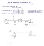
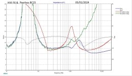
I am posting the XO network I designed and a couple of the graphs.
I would really appreciate your feedback and suggestions on how to improve or to learn what errors I made.

I did try this with 3 different tweeters and 5 different drivers. This particular combo gave me the best graph with the simplest XO and lowest part count - thus the cheapest option. Other combinations produced better looking graphs, but the XO network and part count put the project into the $350 to $800 range! I am budgeting about $300 for components (including drivers).

Attachments

  • HiVi F6 Peerless BC25 XO Diagram.jpg
    HiVi F6 Peerless BC25 XO Diagram.jpg
    57.4 KB · Views: 170
  • HiVi F6 Peerless BC25 XO FreqPhase.jpg
    HiVi F6 Peerless BC25 XO FreqPhase.jpg
    171.4 KB · Views: 160
  • HiVi F6 Peerless BC25 XO imp.jpg
    HiVi F6 Peerless BC25 XO imp.jpg
    191.2 KB · Views: 158

Calculate Xmax

Hi everyone,

I want to be able to create my own enclosure for some woofers that I am recycling from some old equipment, and I wanted to calculate their response in WinISD, and by inserting the Thiele-Small parameters, I realize that they ask me for Xmax. As they are recycled woofers, I do not have the Thiele-small parameter table provided by the manufacturer, so I had to do all the measurements manually in REW, using a non-amplified system, but this measurement does not allow you to calculate Xmax.

My question is if Xmax can be calculated in some other way, knowing other T/S parameters, or I don't know, in some other way that does not require many very sophisticated measurement tools.

Anyone still using IB subwoofers in 2024?

I acquired a pair of vintage subwoofers; MB Quart QM340CX. I’d like to install them in my ‘83 380SE. But, I’m looking for a vintage-style installation. In the past, it’s popular to install subwoofers in infinite baffle style, put the subwoofers on the rear parcel shelf. I’m so interested in it.

Is there anyone still installing the subwoofers on rear parcel shelf in these days? Also, are my subwoofers suit for rear parcel shelf installation?

T/S parameters of the QM340CX:
Impedance 4 Ohm
Re 3.4 Ohm
fs 44.2 Hz
Qms 8.51
Qes 0.77
Qts 0.71
Le 0.89
Vas 55.8 Liter

IMG_8601.jpeg

Switching Noise DC-DC Converter

Hi,

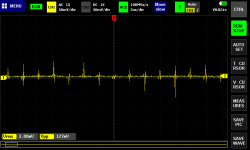
Is the switching noise what makes people not use dc-dc converters in sensible audio circuits such as DACs?

I can't think of a external filter for the output, as the problem is not the ripple but this high frequency switching. 🙁

Many professional audio interfaces use dc-dc converters followed by an LDO. But won't an LDO block these high frequency spikes!? 🤔

Is this the reason that most people on the forum prefer to continue with linear PS?

Attachments

  • switching-noise.png
    switching-noise.png
    5.1 KB · Views: 192

Sealing old chipboard boxes prior to painting?

Almost up to the finishing stages. Because I am using old boxes for these outside speakers [ but under shelter so not rained on] I need to paint them. The old plastic veneer is off and the build has a lot of cracks and the chipboard isn't in good condition. Has anybody ever used gesso to seal boxes before painting? If so do you have a recipe that uses Bondcrete PVA plus sawdust as part of the mix? Also rather than calcium carbonate as the filler has anybody used Plaster of Paris?
I don't want to spend too much more on these boxes than I have to but they will look a bit better with coat of paint

SEAS driver choice for first build and some xMax problems

Hey guys, I have been reading a lot of your discussions and I recently joined to be able to discuss some things in more detail.

I am building my first speakers, they will be a curved bookshelf design, with some similar shapes to Sonus Faber. They will be front ported in a similar design to the TAD speakers and I will be trans laminating CNC cut wood like the TAD Reference Ones.

I would like to use an Aurum Cantus G2 ribbon tweeter from the 90s but I am willing to change this if I get some different recommendations.

My question, and problem so far, is woofer selection. Any woofers I choose seem to hit Xmax pretty bad in my 650 cubic inch enclosure (final enclosure will be between 450 to 700 cubic inches depending on driver selection).

The first driver that did not hit Xmax in my design was a SEAS 7" Curv woven poly. All tho it can go up to 4000hz, I read that I should go with a smaller woofer to match a ribbon tweeter that only goes down to 2.5k hz, is this correct?

So I found some SEAS 5" Magnesium woofers, the Excel W15CY-001. But these hit xmax in my box no matter what I do. I do not want to reduce the enclosure size too much because I would like to keep a nice bass extension.

Which of there two woofers would you guys recommend? And is there anything I might be doing wrong in WinISD that makes my drivers hit Xmax at half their rated wattage? I see similar designs online with the same drivers so I do not know how other designs can pull it off while I seem to be hitting Xmax in my simulations.

Other drivers I had my eye on are the 6.5" AC-165 Aurum Cantus Kevlar and Carbon fiber woofer and the Kartesian Wom165 MS or Wom145 MS.

Thanks you very much in advance.

Von Schweikert VR1 Crossover upgrade

I'm about to try a crossover upgrade from my Von Schweikert VR1 bookshelf speakers.
However, Im not sure of the cap value.
Has anyone done this to this speaker? It's getting on in age now but I quite like its presentation and having done crossover cap upgrades before I know how much it can improve a speaker's performance.
TIA for any info anyone might have.

A Trans-Atlantic Collaberation: High Gain Tube MC Phono Pre-Amp

Hi,

I guess at some point we should work on that head amp we've been discussing for a year. I suspect there is an ideal Russian tube...

Yeah, wouldn't that be great?
A dedicated MC phono stage would be quite something.....
As for the russiaqn valves, I was thinking about the 6S3/6S4 (what's the difference?) based on it being their equivalent of the EC86 but looking at the USSR sheets it doesn't seem to be a true equivalent or am I missing something?

Cheers, 😉

Suggest some tubes?

I recently purchased a power transformer and a pair of single ended output transformers relatively inexpensively. The PT is rated at 250 volts at 200ma and 6.3V at 3.5 amps. The output transformers are 15 watt, 3.5K to 8 ohm, 40% screen tap.

My initial thought was 12ax7 and EL34 tubes. But I'm open to suggestions. I won't be building this immediately, but it will probably be my winter project. Please give me your thoughts. Thanks!
Projects by fanatics, for fanatics
Get answers and advice for everyone wanting to learn the art of audio.
Join the Community
507,663
Members
7,883,216
Messages

Filter

Forum Statistics

Threads
405,982
Messages
7,883,216
Members
507,663
Latest member
The driver