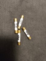
Caution ! Cheap fuses

You clever lot may already be aware of this but it’s new to me 😁

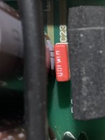
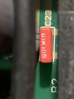
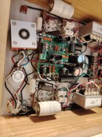
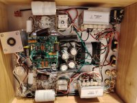
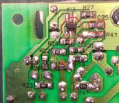
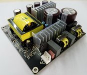
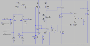
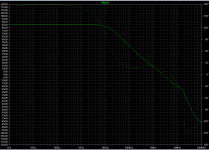
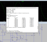
I bought a none working power amp ( owner had somehow touched the speaker wires together) so the first thing I did was check the 4 internal 3.15amp fuses for continuity and they had all blown , as I didn’t have any of those fuses I risked wrapping some thin wire around the old fuses just to test ( I don’t recommend doing this) and hey presto it worked and the amp sounded very nice . I then ordered some replacement fuses from Amazon prime ( being impatient) , they promptly arrived the following day , fitted my newly acquired fuses and “ Hmmmm ! Now what’s wrong? “ I thought, sounds all distorted, perhaps there’s something else wrong like caps or the transistors. I went about changing some of the small value caps and removed some of the larger caps so that I could test them and they were still within their tolerance, plugged the amp back in and it still sounded distorted so I then went back to the wire wrapped fuses that I made and again gorgeous sounds 🤷‍♂️
I then bought some Bussmann fuses locally and yes the amp sounds fine . Next time I see 1 fuse for sale at £600 I may not be so quick to judge. 😁

Hello from upstate NY!

Hello from upstate NY!
I love this hobby.
so...
My setup
Head end Allen & Heath Xone 92 analog DJ distribution mixer
TAD TSM-300 Studio Monitor powered by Willsenson R8 w/ EL34P or JJ's
KRK V88 monitors (plate amp disabled) w/ ESS AMT Hi Freq drivers, Bi amp tube amps, Dr. Bag custom PP amp and upgraded Douk KT88
DBX 234 electronic crossover
Lii Silver 10" stone open baffles via Douk B300 mono blocks tube amps
Dayton sub amp >>> CSS SDX12 Dual APR12 subwoofer enhanced by DBX 510 subsonic synth
Bob Carver Sunfire subwoofer
Denon & Tascam CD players
Dragonfly RED DAC
Headwrecker folded horns powered by Decware SEUFO84/ with copper caps upgrade
Fluance RT85 / Ortofon 2m blue

Obligatory introduction . . . so I can post some advice to an existing thread

I am a first-timer to this forum.

I am informed by diyAudio's registration process that I have to initiate a new post before jumping into an existing thread and offering advice.

Okay . . . so follow me over to here:

"New owner of Beveridge Electrostatics!"

URL: https://www.diyaudio.com/community/threads/new-owner-of-beveridge-electrostatics.348422/page-3

SMPS to run Gu50 heaters? Extra filtering?

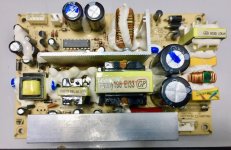
Greetings Friends. I need a 12vDC power supply to heat 2x Gu50 tubes for an amp. While the Hammond 166L12 is one option, I'm curious about these small n cheap SMPS they got nowadays. Here's a SMPS on Ebay, 12V 2A. Gu50 need 0.8A per tube, so 2A should be plenty. Is this a viable option for powering tubes? Would a 6800uF 25V (audio grade) cap be useful across the outputs?

thanks for taking a look!

will

For Sale Miro's TDA1541A d and PSU - UK

Giving someone the opportunity to try this DAC. I built it up with all top components pretty much all new from Mouser.
TDA from a Philips CD. Removed myself with care, it desoldered easily and without much heat.
Doesn't include opamps but I did socket the IV resistor location. 'IV to taste'! Or budget.
Obviously have quite a bit invested in this. It is untested but have no reason to doubt my work atleast.
Asking £175

PSU also available, built with Pana FC/FM/Wima etc. Used the lower noise MCTG regs. I think I did test this but not totally sure but not much to get wrong.!
Uses 25v caps so watch your rectified voltages.

£35.

Buy the DAC and get the DC blocker FOC.

Attachments

  • IMG20240704065223.jpg
    IMG20240704065223.jpg
    374.1 KB · Views: 138
  • IMG20240704065239.jpg
    IMG20240704065239.jpg
    342.8 KB · Views: 128
  • IMG20240704065246.jpg
    IMG20240704065246.jpg
    280.9 KB · Views: 126
  • IMG20240704065300.jpg
    IMG20240704065300.jpg
    403.9 KB · Views: 119
  • IMG20240704065304.jpg
    IMG20240704065304.jpg
    386.2 KB · Views: 112
  • IMG20240704065315.jpg
    IMG20240704065315.jpg
    365 KB · Views: 108
  • IMG20240704065425.jpg
    IMG20240704065425.jpg
    380.7 KB · Views: 121

Dual TDA1541 Dual balanced DAC PCB (batteryman)

I have been listening to various dacs over the last few months, including a Cambridge Audio Dacmagic (dual TDA1305), Chiurutu's discrete logic ladder dac, and a Topping E30 dual AKM 4493. Years ago I built an Audio Note DAC1 (single AD1865) and valve output stage.

But then I go back to my dual TDA1541a dac, and realise everytime that I it prefer over all the others although I can't explain why. I think it's like comparing fresh water with distilled water - they are both H2O but the distilled water is bland.

I built it with Nichicon UKL ultra low leakage 100uf dem caps and use IanCanada's Fifo II and I2S to PCM board to supply the +- data for simultaneous mode. The dem clock runs at the specified frequency. I2S comes from a DIR9001 coax/optical interface. (or originally, direct from a CD player modified to provide I2S)
I/V is thanks to a pair of Sowter 1465 I/V transformers with 75r resistors. (there is no issue with the output offset current)
Power is from a Lithium battery bank with onboard low noise regulators.

I now want to experiment with other dem caps so have ordered 20 boards and 15 will be available to members.
If anyone wants one, please let me know. The cost is about £5ea + postage. (cost confirmed when they are delivered in case taxes are added)

The design is below and it is what it is and is far from perfect but cannot be changed. There are no surface mount parts.

bmadac.jpg

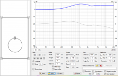
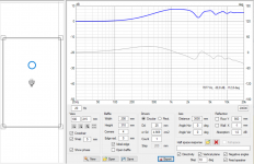
Dipole peak of naked driver array ?

This OB speaker is in the planning stage albeit I already have the mid range drivers. The mid / tweeter section will look like this:
IMG_0898.jpeg

The 16 mid range drivers are 2.5” BMRs which I intend to use over c. 200hz to c. 3500hz. The central tweeter is a ribbon. Although I have shown space between the drivers, in practice they will be edge to edge and joined together and suspended by paracord so as to be baffle-less.

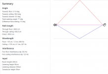
I have heard some box speakers that used a somewhat similar array of full range drivers (albeit just used for mids) and subjectively the array sounded like a single wide dispersion source. However, what I’m struggling to get my head around is what the dipole distance will be for such an array and therefore what the dipole peak will be.
I’d welcome the thoughts of those on this forum who have taken a deep dive into dipole behaviour.

For Sale Scanspeak 18WU/4741T00 & Scanspeak R3004/662000

ScanSpeak 18WU/4741T00: Bought and tested but ended up not using them. $385/ea new. $600 shipped US

Scan Speak R3004/662000: Purchased via Madisound for a Troels project and I ended up going in another direction. Have never seen power. $286/ea new, $500 shipped US

More pictures available upon request.

Thanks!

Attachments

  • PXL_20231101_152145362.jpg
    PXL_20231101_152145362.jpg
    384.8 KB · Views: 175
  • PXL_20231101_152201668.jpg
    PXL_20231101_152201668.jpg
    454.6 KB · Views: 166
  • PXL_20231101_152439638.jpg
    PXL_20231101_152439638.jpg
    274.4 KB · Views: 167
  • PXL_20231101_152512436.jpg
    PXL_20231101_152512436.jpg
    486.9 KB · Views: 153

Discrete 2N4403 from 1976, same noise performance in Moving Magnet RIAA preamp, as NE5534A. And better performance than the dual (5532A)

John Curl filed a patent application in March of 1976, which eventually was granted as US Patent # 4,035,737. His invention was a moving coil pre-preamplifier which used the low noise {for 1976!} discrete transistors 2N4403 and 2N4401. I wondered how well those old transistors would perform in a Moving Magnet RIAA preamp, where the current noise is paramount because of the 47K cartridge loading resistor.

To get started, I looked up the base resistance r_bb of those devices in The Art Of Electronics, 3rd Edition (by Horowitz and Hill). As expected, the PNP's base resistance was lower (r_bb = 17 ohms !) so I focused upon a moving magnet design with PNP input devices: 2N4403. The other transistor parameter needed for noise calculations is the current gain Beta, which I measured on six units using a curve tracer. As Figure 1 shows, Beta exceeded 160 on all six devices, for all collector currents greater than 30 microamps. Thus I used Beta=160 in the noise calculations.

Figure 2 is the equation for the input voltage noise density of a differential pair of bipolar transistors. (It's from George Erdi's ISSCC paper on the super low noise LT1028; written in 1986). As you can see, voltage noise density varies with temperature, collector current, and base resistance r_bb. (notice that Beta does not appear)

Figure 3 is the equation for the input current noise density of a bipolar transistor. (From Horowitz and Hill TAOE, 3rd Edition). Current noise density varies with collector current and with Beta. (But not temperature or base resistance).

The only one of these variables under the control of the circuit designer, is collector current. So I plotted input voltage noise, and input current noise, when varying collector current. These plots are Figure 4 and Figure 5, respectively.

The voltage noise plot in Figure 4 contains a few surprises. First of all, the 2N4403's input voltage noise {red curve} is better than the (dual) 5532A, for every single collector current I tried (40uA <= Icollector <= 300uA). Second, the 2N4403 noise turns out to be less than the 5534A, for every collector current greater than 70 uA. Not bad for a fifty year old jellybean part.

The current noise plot in Figure 5 tells another story. As mentioned above, the very low base resistance of the 2N4403 makes no difference to the input current noise; only Beta and collector current matter. The 2N4403 is lower noise than the 5534A at low currents (Icoll < 80uA) and higher noise than the 5534A at high currents.

Like our colleagues at Philips (later Signetics) who designed the original 5534A, we have discovered there is a "sweet spot". Namely, at 70-80 microamps of collector current in each input 2N4403. This sweet spot gives an input current noise density of 0.4 pA per rtHz (same as the "Typical" spec for 5534A), and an input voltage noise density of 3.3 nV per rtHz (while 5534A "Typical" spec is 3.5 nV per rtHz). Both of these are way, WAY better than the dual 5532A's specs.

Now, if you wanted to build a moving coil preamp (as John Curl did in 1976) instead of moving magnet, you'd be interested in the input voltage noise density. Why? Because the 47K cartridge loading resistor of MM preamps goes away, and is replaced by a ~100 ohm loading resistor for moving coil cartridges. So the (CurrentNoise * LoadingResistor) contribution to noise voltage becomes negligible. Let's go back to Figure 4 (2N4403 voltage noise) and see what can be done....

Cowabunga! Simply by raising the collector current, we can decrease the input voltage noise density dramatically. At Icollector = 250 microamps per transistor, we get a 2x reduction in noise compared to the 5534A. And, as John Curl's patent carefully explains, by connecting several of these transistors in parallel, we can reduce noise yet further. Not bad at all, for a fifty year old jellybean part.

_

Attachments

  • 2N4403_beta_vs_Icoll_fixVce_5v.PNG
    2N4403_beta_vs_Icoll_fixVce_5v.PNG
    22.2 KB · Views: 317
  • diffpair_voltage_noise_LT1028_ISSCC_1986.png
    diffpair_voltage_noise_LT1028_ISSCC_1986.png
    4 KB · Views: 281
  • current_noise_TAOE.png
    current_noise_TAOE.png
    41.7 KB · Views: 295
  • Voltage_Noise_diff_2N4403.png
    Voltage_Noise_diff_2N4403.png
    20.2 KB · Views: 284
  • Current_Noise_diff_2N4403.png
    Current_Noise_diff_2N4403.png
    20.8 KB · Views: 299

Beosound 9000 problems

I have two different editions beosound 9000 with problems,
both did not read cds, I changed the laser mechanism in the first one and now it shows the following
the change was not successful, it goes to the number of the CD that I choose,
it starts to turn but vice versa (anti clockwise )and the display says load
I also removed a gray connector p9 that went from the power supply to the motor control unit and put it back in.
Now the standby LED doesn't light up and it doesn't even go into test mode.
the radio and the rest work normally.
it is connected to its speakers beolab 8000 and the remote control works.

the second one mk1 had a problem with its power supply the 9 and -12 volts failed I changed the ic100 dual mosfet WAS SHORT and the resistor r157 33R OPEN and the IC3 LM3578 THE voltages came in and then I found a short circuited zener diode d64 15volt in 9volt rail.
which I changed now it opens normally, but in the mode of the cd, when it gives an order to play , the voltage of 9 volts begins and drops and the device goes to standby, does anyone have experience with this I want to see if the problem is in the power supply or in the mechanism of the SD
it is connected to its speakers beolab 8000 and the remote control works.
no standbuy led and it doesn't enter state test

Screenshot 2024-06-26 at 16-16-48 bang-olufsen_beosound-9000_mk1 9v cd.png


mode

any help would be greatly appreciated

Powersupply_M.jpg

Speaker analysis is hard, so 1m measurements are the way to go!

Hey everyone,

I wanted to post a think-piece about learning to do speaker analysis. In particular for a beginner starting out with a 2-way system and using in-room measurements may be the very best way to get started.

Of course there will be room interactions not fully accounted for, but maybe a measurement which gates the tweeter/mid-woofer crossover areas and then blends that with the mid-woofer's low end response is the best way to get started?

With 1m measurements there are a few complications we avoid (compared to quasi-anechoic), such as:

  1. Integrating the port (if any) with the woofer response
  2. Adding baffle step calculations
  3. Understanding boundary reinforcement and how that will shape the final outcome.
Even with 1m measurements there are still a couple of things which are going to be a little difficult:

  • Measuring the acoustic offsets
  • Measuring off-axis to pick ideal crossover location.
What do you all think of this as a solid learning path for most beginners? Would you suggest another direction instead?

Hatred towards resonance

The series notch filter is used for eliminating/reducing impedance peak at resonant frequency of any drivers. However, since the frequency response curve of most drivers provided by manufacturers still can be roll-off smoothly at the low frequency side, why do we need to eliminate that impedance peak due to resonance? Please help recall my memory.

Also, most of modern speakers tend to have crossover points at lower frequencies compared to those loudspeakers in the 1980s. For instance, the modern 3-way speakers have 200Hz and 2kHz while the 80s speakers had 450Hz and 4.5kHz crossovers. However, I found some of those modern speakers haven’t had any (series) notch filter to handle the impedance peak at resonance anymore. So, does it mean some designers ignore that impedance spike? In all, is the imp. peak/resonance really matter?

RAFFLE - Power supplies for new Aleph Jzm Kit

In celebration of the launch of the new Aleph J Zen Mod edition, I'm offering up 1 fully built PSU and 2 power supply PCB kits to Aleph Jzm builders.

24 May 2024 - UPDATE - I found the pre-built PSU in my stash that I was looking for. I'm adding that to the raffle prizes!
#1 GRAND Prize - Choice of Fully built stereo Supply, 2 Rectifier snubber PCBs, 2 bridges - OR pass this to the next winner and go for one of the other PCB setups
#2 & #3 - Choice of one of the 3 PSU board kits below. I'll include bridges. If you get the stereo PSU I'll include Panasonic 0R47 Resistors.

Of course, anyone is welcome to enter, but it would be ideal if these boards went to new builders looking to get started with their first First Watt project.

Winners have the choice of 3 power supply styles from my stash:

For a single donut stereo build: 1x "New original" F5 dual rail decoupled power supply board and 2 rectifier / snubber boards. This is the Power Supply shown in the brilliant build guide by @ItsAllInMyHead

If you're considering a dual mono or monobloc build, there are 2 additional options available.
For monoblocs: 2x V8 CRCRC power supply boards, 2x CL-60/AC Cap boards, and 4 rectifier / snubber boards
For 2 donut dual-mono build: 1x W12 CRCRC power supply boards, 2x CL-60/AC Cap boards, and 4 rectifier / snubber boards

Rules:
To be eligible you must be committed to using this on AJzm amp build
Must built by end of 2024 (I don't want the boards sitting in drawers)
I’ll cover shipping within the USA. Outside USA I'll cover shipping up to $10 USD. I'll ask you to cover any additional cost.
I’ll keep entry open until 12 noon Eastern time on Monday 03 June 2024. From there, I’ll take the last post that contains all entrant names, randomize with random.org, and the top 3 spots will be the winners. Spot #1 will be the Grand Prize winner. I’ll post the screenshot - it’ll be the winners' responsibility to pm me with their shipping info.

Attachments

  • 3 PSU Options.jpeg
    3 PSU Options.jpeg
    620 KB · Views: 299
  • Power Supply Option Overview-00a.JPG
    Power Supply Option Overview-00a.JPG
    142 KB · Views: 291
  • IMG_1745.jpeg
    IMG_1745.jpeg
    460.4 KB · Views: 188

Grounded grid preamp voltages

I have a Grounded Grid preamp. The board is from Analog Metric in Hong Kong. When checking the voltages without tubes the voltages are substantially higher than specified.

HT is 16,9V. It is supposed to be 12,6V
+200V is 236v
-200V is 238V

All components seem to be the correct ones (I have however not measured them).

Is this big difference to be expected, or is something wrong?

Attachments

  • IMG_0667.jpeg
    IMG_0667.jpeg
    572.1 KB · Views: 211

Hello from downunder

Hello DIY'ers, I've been an avid reader of this forum for many years and finally decided to sign up!

I'm into designing my own speakers for both commercial and diy use from the likes of atlasharmonic (formerly Atlas and Hurd) and thespeakerproject.com.

Only here to read what people are building and comment from time to time.

Thanks for having me!

Cheers,
Atlas.
  • Like
Reactions: Stanislav

JFETs from Linear Systems

Exciting news! The diyAudio store is now the exclusive distributor for limited quantities of LSK170 and LSJ74 JFETs from Linear Systems.

Watch the announcement from Linear Systems on YouTube!

Please post any questions you have in this thread. We'll be posting information shortly about the difference between the grades. Depending on your application, different grades may be the most suitable.

A comment from Nelson on grades:

Nelson Pass said:
The B through D and most of the A would not be a problem for the ACA, and a slight adjustment would allow down to the 2.5 mA figure without problems. Most of my projects would want a B or C grade as most desirable, but it’s not a big deal.

Dead tweeter in Tannoy Mercury M1

Newbie here. I just picked up a pair of Tannoy Mercury M1's for free. The owner said the woofer was dead on one and I thought it would make a suitable first DIY audio repair. I connected it and the woofer wasn't dead but was sounding like a tweeter. Opened it and sure enough someone had connected the tweeter wires to the woofer and vice versa (maybe when they were adding polyfil to the cabinets). Checked the tweeter with a 1.5 voltage battery and it was definitely dead. I had an old pair of Gennexa (optimus) Pro X7s in the basement with tweeters that looked almost the same (both speakers are 8 ohm though the Gennexa's are 89 db sensitivity and the Tannoys are 87 db). After fashioning a new mounting plate for the tweeter out of fibre board, I connected the tweeter and was pleasantly surprised that I couldn't hear a discernable difference between the two speakers. What I'm wondering though is whether the original tweeter might be salvagable and how difficult/expensive it would be to fix it? Thanks.

Blowing the dust off my Hifonics Boltar VIII

Hi again!

Going through some of the old school amplifiers I have accumulated over the years, and I still have a Hifonics Boltar VIII, A few years back I posted on this forum looking for the connectors. I did contact Steve at Zed who would sell me a used set for $100, not worth that to me so I will probably remove the connectors and replace them with something else or solder wires directly to the board.

While exchanging emails with Steve, I started to discuss the updates/upgrades for this amplifier. It is a service he offers for a reasonable charge, but it is more that I want to spend on it. Unfortunately, he has no support for DIY types. It would have been great if he sold a parts kit and instructions.

So, first question is- Anyone else know the details of the upgrade process? Replacing the capacitors is pretty obvious, but he also mentions modifying the power supply (drive circuit, and regulation). He also mentioned those upgrades in this post: https://www.diyaudio.com/community/threads/hifonics-boltar-viii.367163/

Second question is- even though I think this amplifier works, there are two resistors that look to be "crunchy". One is labeled R14, the other (right next to it) I can't read. My thought is to remove them, and measure but that may not be accurate considering their appearance. Anyone know what this is supposed to be?

Also would love some schematics, if they are out there.

Thanks!

Hybrid bias for output stage

Hello!

I have a question. We discuss very often the pros and cons of fixed vs self-bias for output stages. But I do not see often hybrid bias, where self-bias and fixed bias are combined, into something like this:
1708089497212.png

What are the drawbacks of this approach? I can understand that it is a bit more complex, even when the current source is replaced by a resistor. But I can see a big advantage, which is reducing the power dissipation of the bias component, while still retaining some of the self-bias advantages. Using a CCS instead of the bias resistor makes it even better.
I'm sure it is used somewhere, but not very often. Any ideas?
Regards,
Jose

DIY Internet Radio

I would like to share with you my project - Internet radio with touch screen and stations web management system
1716592634700.png


See it on youtube:
Login to view embedded media
It is very easy to build using only 3 components: Login to view embedded media
My YouTube channel contains various versions, including one with SPDIF Hi-Fi output:
https://www.youtube.com/@arielhhhhh

Article about the internet radio:
https://www.hackster.io/news/build-your-...59513be786

Software, documentation and enclosure 3D print files:
Internet_Radio

Build it yourself option:
https://www.tindie.com/products/33913/

This is my first post

I joined in 2012 but never posted. Now I have more time to work on my hobby. I have DW loudspeakers now since 1977, had those replaced under warranty in 1980. And with some maintenance they lasted until 1999 when I took them apart after several cells had died. I now own a pair of Martin Logan ESL. Since the Dayton-Wright site is no longer functional, I thought I'd post an analysis of how the loudspeaker developed over time and all the engineering decisions Mike told me about. So these posts are on the Martin Logan users forum.
I used have amplification on the cheap by using two bridged Hafler amps. In the mid 80s I designed my own amp for them, which served me well and i still have it running today into conventional speakers today. Back in those days we did not have WiFi so the amp has no protection against that kind of local high power ingress. The caps are all tired now, so its time for a rebuild.
Here is a picture of a dual mono amp with power supply shoehorned into a Hafler DH100 case, but using 6 output devices per channel.
Anyhow I had to post here before I could post an answer to someone that just bought a non functional DW speaker recently.

Attachments

  • Hafler_mod1.jpg
    Hafler_mod1.jpg
    447.6 KB · Views: 45
  • Hafler_mod2.jpg
    Hafler_mod2.jpg
    552 KB · Views: 48
  • Like
Reactions: Jason and adason

Single CD drive mechanism to suit 2011 Hyundai iLoad. This drive mechanism is so far, impossible to locate on the net. Help please.

Does anybody have any idea who makes these radio's, and where am i likely to obtain a single drive CD mechanism complete to suit this radio?. I've looked high and low, with no luck. I have sent emails, with no reply. There are millions of these cars made all over the world. One would think that a couple of the sites i looked at had heaps and heaps of mechanisms, but none the same as these. I have three to repair, so far, and they are quite easy if you could ever get one of the CD drive mechanisms. Somebody obviously makes these radio's, but it appears to be a big secret, for some reason. I got one reply from one manufacturer, who makes these units for just about everything else, but Hyundai iLoads. They have to exist, it's just a matter of perhaps somebody out there who has fixed one of these before now. Another problem with these radio's, which is the standard radio in these cars, is the four screws that hold the bottom circuit board, come loose real easy, and maybe short something out, not quite shore, but, if you ever buy a new one, the first thing to do is take the top cover off, remove the CD drive unit, and tighten those four screws. Any help in purchasing a couple of these drives would be greatly appreciated. Thanks, and i love this new site, as i am fascinated with this stuff now and have been for a while, after a few mistakes that is. Cheers, Wal.

As I create my first amplifier diagram, I eagerly await your feedback

Hi everyone. From an academic sense, I know very little about power amplifiers and circuits. I have learned a great deal about amplifiers from YouTube and the DIY audio community. To gain some understanding of the fundamental construction of a transistor amplifier, I have collected some circuit diagrams related to amplifiers from the internet and some sketches from the PCB. what I have learned or what experience I have gathered, or, you may say, stolen, 🙂 which I wish to implement on my own designed PCB. This ambition led me to create this schematic. In order to create the amplifier, I would like to ask that you provide some valuable advice and constructive criticism prior to routing the PCB.
🙂
Thanks
OPU

Attachments

  • new_amp.png
    new_amp.png
    359.4 KB · Views: 371

The frequency at which the Rockford t1500 1bdcp amplifier driver operates floats away

Hello! I have a problem with the t1500 1bdcp amplifier. At low volume there is constant noise after the amplifier warms up. It looks like the problem is in the throttle output ring. it seems to have lost inductance. can you please send me the circuit diagram of this amplifier? I want to replace the ring and throttle, but I don’t know which one. The frequency at which the driver operates disappears; it is not clear why this happens. I checked all the little things, everything is fine. There is a suspicion that the ring on the output choke has lost its inductance due to time and heat. The amp also gets very hot even when not playing.

The ultimate speaker measurement setup?

Hi Forum
It has been over 6 years ago that I build my big 3 way speaker.
"building the best 3-way full range speaker"

Earlier this year we did a big renovation of the living room with attached kitchen and when this was done, I found the speakers a big too massive.
Maybe it is my age and the testosterone is diminishing but the speakers always were big.

So I am starting a new design, with 20% smaller footprint and 30% less volume.
Still a large speaker but a bit better suited to the room.
I will start a different thread on this built.

But..... I want to improve some parts on a design that will borrow a lot of the original as to my ears it is still a fantastic sounding speaker.
In the preparation to this new design I want to simulate better and measure more precise.

So, I bought an Earthworks M23R reference microphone.
This unit has an insane flat curve with a correction file that onlu has +/- 0.16dB of correction.
I designed a new mic stand by combining some parts of existing good available mic stand parts.
The reason not to go with a standard mic stand is the possible reflections the boom and mic-clamp can introduce.
So the ideal speaker measurement setup is kind of a floating microphone with nothing close that can cause reflections,

The parts I used are:
  • The main tube of a Gravity MS 23 XLR B Microphone Stand
  • K&M 252 Black standard mic stand where the main tube is build out of 3 parts so the vertical pole can go pretty low
  • An Adam Hall SDMSB 190 Stereo Bar that gets mounted on the K&M stand by standard 3/8” threaded bolt
  • A K&M 21105 Counterweight (that I mount to the mic tube with a rubber door stopper)
  • Some bolts, nuts, washers and 4 black electricity tube clamps.
And this is the result:

Attachments

  • IMG_5130.JPEG
    IMG_5130.JPEG
    743.1 KB · Views: 318
  • IMG_5131.JPEG
    IMG_5131.JPEG
    547.2 KB · Views: 290
  • IMG_5132.JPEG
    IMG_5132.JPEG
    464.3 KB · Views: 262
  • IMG_5133.JPEG
    IMG_5133.JPEG
    488.7 KB · Views: 294
  • IMG_5134.JPEG
    IMG_5134.JPEG
    801.5 KB · Views: 307
  • IMG_5135.JPEG
    IMG_5135.JPEG
    1.4 MB · Views: 411
  • IMG_5136.JPEG
    IMG_5136.JPEG
    440.4 KB · Views: 294
  • IMG_5124 no serial.jpg
    IMG_5124 no serial.jpg
    382.1 KB · Views: 298

JL 1000/1 Low ohm light

Amp came in with low ohm light lighting up and barely any power draw. I found Q835 which is an FQP30N06L signs of overheating. I replaced this part with IRFZ44. The low voltage supply will turn on with 1A for 15 seconds. The new IRFz44 gets raging hot. I put a small sync on it for now.

The amp does fully power up but with Q835 overheating its not stable to test much out. Gate looks alright, a +4v square. It could be cleaner but seems to be alright. Drain is very jagged. Looks like a downward 2 steps. I would have expected this to be cleaner. First image is with REM quickly applied. Second image is after about 15 seconds. 10vDiv, 2uS. There is always about 13v on drain.

Gate resistor for Q835 is 47 ohms and absolutely fine.

The 0.1ohm resistor and 33ohm resistor near Q835 are good. All diodes before and after the low transformer are measuring OK.

U802 is measuring:

1: 13.6
2: 0
3: 5.01

OpAmp regulated voltage seems OK at +-14.6v
Any thoughts as to why Q835 is overheating?

3-Way active DSP speaker with Faital and Dayton

Hello,

my friend Oli (Rese66) told me, that some of you might be interested in my current project. So I post some photos and in case of any questions, I will try to answer them. Okay off we go.

What is in the speaker:
1x Faital 18XL2000
1x Faital W8N8-150
1x Beyma TPL150 the Horn only
1x Dayotn AMTPRO4
2x t-amp Quadro 500 DSP

And here some pics of the speaker build. I name the speaker "fatally", because of the Faital speakers and it's enormous output.
933968d1616230903-3-active-dsp-speaker-faital-dayton-20210220_133953_resized_1-jpg

933969d1616230903-3-active-dsp-speaker-faital-dayton-20210306_161343_resized_1-jpg

933970d1616230903-3-active-dsp-speaker-faital-dayton-img-20210315-wa0005_resized-jpeg

933971d1616230903-3-active-dsp-speaker-faital-dayton-20210312_213857_resized_1-jpg

Attachments

  • 20210220_133953_resized_1.jpg
    20210220_133953_resized_1.jpg
    697.1 KB · Views: 1,245
  • 20210306_161343_resized_1.jpg
    20210306_161343_resized_1.jpg
    822.9 KB · Views: 1,274
  • IMG-20210315-WA0005_resized.jpeg
    IMG-20210315-WA0005_resized.jpeg
    537.3 KB · Views: 1,211
  • 20210312_213857_resized_1.jpg
    20210312_213857_resized_1.jpg
    624.8 KB · Views: 1,272
  • IMG-20210315-WA0014_resized.jpeg
    IMG-20210315-WA0014_resized.jpeg
    550.3 KB · Views: 382

Biasing target for push-pull amp

I have created a 10W amp (2.5A) in QSpice and I'm preparing to build a prototype on Perfboard.
My question is what should I target for the current across the diodes?
I have attached datasheet screenshot. My interpretation is I'll only need 7mA which seems too low.
Please take a look at the datasheet and advise me if I've got this calculation wrong.
Both hFE and fT are over 270mA and 270MHz respectively.

Also, I have the option to use dual channel. Advisable or superfluous?

Many thanks for reading.

Attachments

  • 2SC6144SG-SPEC.PNG
    2SC6144SG-SPEC.PNG
    117 KB · Views: 322
  • 2SC6144SG-amp.PNG
    2SC6144SG-amp.PNG
    42.8 KB · Views: 340

Hello From Dallas Texas! Needing some help with Repairing my JL 500/1 amp

I have viewed several great and very informative posts already here on the site regarding my exact amp. Even have noted some of the exact same issues with mine that I know will need fixing.

My first initial question is my gate resisters on the PWR fets are toast of course as seen on many here already. I noted these are 47 ohm resistors I believe Mr. Perry stated in another post. Mine however are not through hole type like I have seen here but mine are surface mount or where I should say they where really smoked! pretty much all crumbled off the board.

Anyway they said 470 on the tops of them but they are only 47 ohm? and Question 2 is one of the pads on at least 1 of the bad resistors surface mount area looks like it was completely burned off and there is nothing left for me to solder a replacement too? What can I do in this case? Wishing mine where through put at this point. Any and all advise would be great! So R605s left Pad looks the worst out of all of them again not even sure what to do with that flux and dab of solder or?
IMG_2853.JPG


Now below this text here is from another JL Audio 250/1 amp where they are using surface mount Resistors as well but they say 470 on them is that still a 47ohm resistor or 470ohm? Sorry for the dumb questions new to this repair thing but find it very interesting! And would love to fix my amp. Also the 2 amps are using the same fets for PWR IRFZ44N which I saw in another post Perry suggests replacing with IRF3205s so will be doing that! Thanks for taking time to review this and for any help guys/gals!

IMG_2854.JPG

8 mystery cases

8 plastic cases containing film capacitors, driver transistors, output transistors, trimmers, heatsinks, and so on, for sale.

Attachments

  • 20240701_164123.jpg
    20240701_164123.jpg
    441.4 KB · Views: 231
  • 20240701_164100.jpg
    20240701_164100.jpg
    371.9 KB · Views: 214
  • 20240701_164051.jpg
    20240701_164051.jpg
    358 KB · Views: 211
  • 20240701_164051(0).jpg
    20240701_164051(0).jpg
    389.5 KB · Views: 211
  • 20240701_164041.jpg
    20240701_164041.jpg
    350.8 KB · Views: 219
  • 20240701_164017.jpg
    20240701_164017.jpg
    405.5 KB · Views: 215
  • 20240701_164011.jpg
    20240701_164011.jpg
    357 KB · Views: 204
  • 20240701_164001.jpg
    20240701_164001.jpg
    392.6 KB · Views: 203
  • 20240701_163956.jpg
    20240701_163956.jpg
    445.5 KB · Views: 226

My Denon amplifier is freaking out , help me fix it

I need help in troubleshooting my denon pma 520 amplifier that started misbehaving recently.A few weeks prior to malfunction
one channel was playing slightly louder than other and it took quite long for the relay to connect.
What i did was to replace old relay but this didnt help . Now the symptoms are ( and were before relay swap)
1. After turning on relay still takes too much time to click
2. after the click amplifier can either:
a) work properly
b) not engaging source selector light , have fixed volume ( quite loud , overdriving my test speakers) and not responding to volume pot or anything else)

turning the cd direct/subsonic/normal selector can temporarily fix the amp ( or spoil if it was working correctly)

I dont know much about electronics but i have multimeter, esd meter and know how to solder so obviously i can change some components like capacitors etc but need instructions/suggestions how to find faulty ones and where to start.

I attached a link to short youtube video showing the issue.
Login to view embedded media

Marantz 250M Repair

I have a Marantz 250M here from the original owner who says it worked fine until he put it in a new system and the speaker leads were shorted blowing one channel.

He had it worked on, but it is still not working. I think it was checked out but not completed.

I have the schematic. Does anyone know the story behind these Motorola SJ2519/sj2520 output devices?
Are they simply beta selected?
The beta range is listed for many of the transistors.

This is a nice looking piece, however it is a rather unusual design. Seems it does not tolerate a shorted output even though it has protection.

Pete B.

For Sale No excuse for having a stereo LM4780

1701547408124.jpg

For sale stereo kitt, price 44€
LM4780TA with PCB with supply and stereo potentiometer bare PCB, also the connectors are included.
Alps Pot and relay aren't supplied, relay is used to bypass Pot.
Tracked shipment to European union
Skematics sended together with articles.
Payment by PP
If you enjoy this kind of stuff maybe check my offers related:
https://www.ebay.de/usr/dialedinmusic?_trksid=p4429486.m3561.l2559

Attachments

  • 1701547408128.jpg
    1701547408128.jpg
    531.6 KB · Views: 114
  • 1701547513895.jpg
    1701547513895.jpg
    479.5 KB · Views: 113
  • 1701547513902.jpg
    1701547513902.jpg
    513.2 KB · Views: 118

For Sale LM3875TF Diy stereo audio set

1702253718285.jpg

LM3875TF stereo set for sale, price 75€, if you wish with heatsinks the price is 106€ solid walnut is included,check pictures..
I also offer this in mono channel and a full diy kitt, if you want to check take a look on the link.
LM3875TF genuine amplifier IC's assembled on Enig PCB's put together with high quality parts: Allen bradley carbon resistors,
Nichicon electrolytic, Evox mkt's and Murata ceramic caps with bare supply, pre-amplifier and Potentiometer PCB,the supply
connector is included.Pre-amplifier and Potentiometer are also Enig PCB's.
Alps stereo Potentiometer and relay aren't supplied, relay is used to bypass Pot.
Stereo amplifier 56 watts rms good for Hifi stereo system or amplified speaker.
Tracked shipment to European union
Skematics sended together with articles.
Payment by PP
If you enjoy this kind of stuff check my stuff related:
https://www.ebay.de/usr/dialedinmusic?_trksid=p4429486.m3561.l2559

Attachments

  • 1701625142381.jpg
    1701625142381.jpg
    631.2 KB · Views: 86
  • 1701625264522.jpg
    1701625264522.jpg
    448.9 KB · Views: 80
  • 1701625023364.jpg
    1701625023364.jpg
    470.2 KB · Views: 74
  • 1702253937505.jpg
    1702253937505.jpg
    505.3 KB · Views: 77
  • 1702253937496.jpg
    1702253937496.jpg
    540.7 KB · Views: 111

Yet Another Aleph J Build

It was suggested that it might be worthwhile posting my experience as a Guinea Pig 😉, but first a BIG THANKS to all who have made this project possible! The level of professionalism and dedication exhibited should be an example to other companies, especially those in the retail segment.

So far my build is moving along nicely, pic to follow, but I wanted to mention a couple of things that I have discovered. First off, though I am using Kester solder w/ rosin, I still prefer the look of the finished product more when flux has been added. In general I'm finding that the less flux the better, it is still a PIA to clean off.

For those who are having difficulties getting some components to line up nicely, things like LEDs, Jumpers etc. I find that putting the slightest touch of solder on 1 hole, heating it and inserting a leg, with LEDs obviously the long leg, till it is properly aligned, solder the other hole then touching up the first joint.

20240326_132405 (FILEminimizer).jpg

What's your method for filling the tiny cracks between plywood sides?

What has everyone come up with for filling the tiny spaces you see in these pictures?

I have been just filling it with putty but the issue is that sometimes the stain doesn't quite take right in that area.
I am considering mixing the putty with some of the stain to hopefully blend it buuutttt, that might just double stain that particular area and make it way worse.

Attachments

  • PXL_20240628_185430972.jpg
    PXL_20240628_185430972.jpg
    352.9 KB · Views: 124
  • PXL_20240628_185425654.jpg
    PXL_20240628_185425654.jpg
    343.7 KB · Views: 123

For Sale Z Foils, Kiwame 2w, Mills 5w

I've quite a few 2w Kiwames and the following Charcroft Z foils & Mills resistors:

1 off 47K
4 off 1K2
2 off 15R
4 off 150R

Mills:
4 off 0R56
4 off 0R47

£10 each for the Foils and £2 each for the Kiwames, £5 each for the Mills. Free UK postage. PM me for Kiwame values, I've boxes full

Kiwames are mostly new, foils & Mills have been soldered
  • Like
Reactions: Matthew78

PM7200 Amp problem

Hi,

Only just joined and apart from my introduction this is my first post.

Hoping someone can help me out here.
My beloved Marantz PM7200 has developed a problem, occasionally when turning on I will get no sound from one or both of the channels, the only way to fix it is to turn the volume up to max and wiggle it about a bit and then the sound comes crashing in. It's usually fine after that.
It's a random fault and I can go weeks without it happening and then it will happen regularly before behaving itself again.
I've had it from new (so at least 20 years old), any pointers would be helpful, I don't think it's the protection circuit problem but I'm happy to be corrected (I've used some contact cleaner on all the switchs, dials etc. but doesn't seem to have improved things)

Thanks,

Hi from Norfolk, England

Hi, glad to be a member of the forum. Have loved and tinkered with Hifi for about 40 years now and no signs of stopping yet.

My current setup is a Michell Tecnodec with modified Rega Arm, Graham Slee Phono Stage, Marantz PM7200 and Dali Menuet speakers. Sounds perfect in my (not too big) front room.
I also can't resist buying up Hifi and Audio bits and pieces whenever I see them (Boot fairs, etc.) and spend many happy Sunday afternoons restoring them (just need to start selling them afterwards as running out of space)!!

Asymmetrical Fs impedance peak

Most speaker drivers have symmetrical Fs impedance peak but there are drivers (woofers and also tweeters) that have asymmetrical Fs impedance peak, which looks 'strange' intuitively if you saw many raw driver Fs impedances. What is the source of this and what are the realworld consequences (mainly audibility) of such an impedance? Thinking mainly about woofers where tipically using the drivers at it's Fs.

Examples of asymmetrical Fs peak:
6-SB17NRX2C35-8-GRAFIK.jpg
https://sbacoustics.com/product/6in-sb17nrx2c35-8-norex/

f_seas_prestige_loudspeaker_tweeter_h1499_27tbcd_gb-dxt.jpg
https://www.seas.no/index.php?optio...xt&catid=45:seas-prestige-tweeters&Itemid=462

Where to get an affordable Icepower 50asx2 btl module ?

Good evening good people.

I'm trying to repair a GK mb112 amplifier. As far as I can tell, the power amp (Icepower 50asx2 btl) is dead. On the manufacturer's website they sell for 77$ in bulk and 152$ a single unit. 152$ is too expensive. It's basically the price of a new TC electronic BAM 200. Since they sell in bulk for 77$, maybe it's possible to find them selling for around a 100$. Do you know somewhere where they sell them at a reasonable price ?

Wow, Flutter & RPM measuring app for mobile phone? (+ Calibration Tapes)

I would like to measure my cassette deck when I get it restored with new belts, and probably checking the turntable too at some point, and thought I would ask where to find a suitable smart-phone app that can do it, if such exists.

Found these two apps on Google Play Store:
https://play.google.com/store/apps/details?id=com.AM.AM.RPMSpeed&hl=en_US
https://play.google.com/store/apps/details?id=com.vinylrpm&hl=en_US

But these seem to be aimed at turntables only, can one use any of these for cassette deck measurements, or do anyone know of an app that can specifically measure cassette deck W&F ?

I assume the measurements have to be done in conjunction with a prerecorded calibration cassette / vinyl.

Thanks

ps. some links to useful SW etc.
The latest version 8 of the WFGUI program by Alex Freed, ANT Audio
http://www.ant-audio.co.uk/index.php?cat=post&qry=library
http://www.ant-audio.co.uk/Tape_Recording/Service/wfgui_8.zip

edit: BTW sources for calibration cassettes and vinyls would be good too, of course Ebay have a lot of stuff as usually but not sure of the quality so recommendations are welcome.

For Sale London, UK - selling some type 46 DHT tubes

46 - Sylvania in original box £65

Postage at cost. I don't post to Italy, China, Singapore. Possibly other Asian countries as well. Japan is OK.

Attachments

  • IMG_6032.jpg
    IMG_6032.jpg
    862.9 KB · Views: 59
  • IMG_6033.jpg
    IMG_6033.jpg
    760 KB · Views: 58
  • IMG_6034.jpg
    IMG_6034.jpg
    908.2 KB · Views: 65
  • IMG_6035.jpg
    IMG_6035.jpg
    810.3 KB · Views: 71

Anyone heard of these “isolation amplifer” ICs from vintage Kenwood equipment?

Hi all,

I have a few 90s Kenwood active crossovers meant for car use and they have an interesting IC(s) right at the input to cancel out common mode noise.

They are given different names in different models and googling the part numbers doesn’t turn anything up.

They can be found in the service manuals for these two:

https://ia902301.us.archive.org/20/items/manual_KEC300_SM_KENWOOD_EN/KEC300_SM_KENWOOD_EN.pdf

Page 9, given as IC1 “lNH-02080”

And for this model

https://ia902308.us.archive.org/32/items/manual_KEC301_SM_KENWOOD_EN/KEC301_SM_KENWOOD_EN.pdf


Page 6, given as IC2 “NH384”

Anyone heard of these, why these rather than the other types of op amp (upc4570) used in these crossovers?

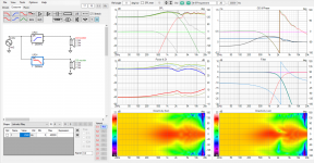
Full VituixCAD simulation workflow? SICA 5,5 coax

Hi,

My wish is to fully simulate speaker with VituixCAD before buying any of the components and building physical cabinets.
Project in details:
-Bookshelf form
-Passive crossover
-2-way with only 5,5 C 1,5 CP coax driver
-Bass reflex 5-10L of internal volume. Manufacturer gives 8L or 9L as recommended in its documentation, quick sim with WinISD also gives "ok" results in 5+ liters range
-Narrow baffle with massive edge radius, 50mm or similar. Only to fit the driver and then some more for rounding/beveling

I already invested some generous two-digit hours of time in understanding some of the Vituix tools, but... Unfortunately it is a tremendously complex software comparable to the collection of the scientific calculators but still with no clear workflow how to actually simulate the speaker in digital form before starting the physical process.

What I did:
1. Took the freely available measurement files in picture format from dibirama.it. I assume they are made on large baffle, 2pi space, 1000mm at 0 degrees H and V.
2. Made FRD and ZMA files with "SPL Trace" tool in Vituix.
3. Simulated Baffle Step Loss with "Diffraction" tool, opened FRD file from my trace, then exported FRD files with 10 degree steps. All the steps above for both drivers - tweeter and woofer.
4. In "Drivers" tab created 2 drivers and opened bunch of FRD files and ZMA file. Everything seems to look ok.
5. Started to play with crossover, manufacturer suggested as a starting point.

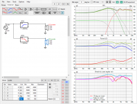
This is what I got with dibirama.it SPL and impedance data AND manufacturer suggested crossover:
muanufacturer.jpg

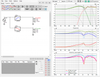
dibirama.it data with tuned values of manufacturer crossover:
muanufacturer+customvalues.jpg

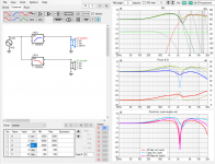
The same with manufacturer data AND manufacturer crossover values:
muanufacturer+mandata.jpg

I do not worry much about the 100Hz range simulation, as the vented box behavior is pretty much clear to me. Also, I have made all the simulations in the virtual 1m distance, because I think the manufacturer and dibirama.it measured at the same distance.

Below are manufacturer polar diagram of separate tweeter and woofer:
polarmandata.jpg


It seems dibirama.it + manufacturer crossover is even better than the manufacturer data alone.

I do believe, that manufacturers make their data by cherry-picking their drivers for measurement or/and simply by painting them to look more beautiful, but my questions are:
-Does the driver look listenable from my simulations?
-If not - what could be reasonable crossover for this driver?
and most importantly:
-Are my simulation steps right?

Here is manufacturer data of the completed speaker with their suggested crossover. All the ripples are in 2-3dB range, but my simulation shows closer to 5-6dB, a pretty big difference:
manspeaker.jpg


It is a pretty expensive experiment to do in physical form, as drivers and crossover components will be at least 250-300EUR, I want to make sure it will not disappoint me. There are not many projects with this driver, and also I am scared of crossovers with ridiculous amounts of components (15+...).

Thank you for your thoughts

Saving my Heath AA-32 amplifier or the lack of available 6GW8, ECL86 tubes

I find the Heath AA-32 a pleasant little amplifier perfect for a office or den.
It is small and simple, gives off moderate heat and in my experience they are long lived and reliable.
Although simple and modest in design and measured performance I find the AA-32 produces a utterly pleasant musical experience when called on to fill in the acoustic spaces in ones den or office with pleasant background sounds to work by. While the output quad of NOS 6GW8 tubes with many hours on them still produces a acceptable amount of output power at moderate distortion they have now lost about half their emissions. One can see the writing on the wall for this set of tubes. So what to do as for me the prices of a set of NOS 6GW8 tubes just does not compute.

My first tact was to switch the outputs with the available and low cost NOS PCL86, the same tube with 13V heaters. Searching for a available small and affordable filament transformer that would fit under the chassis to provide the 13V for the 4 PCL86 proved harder than I expected. There is little space under the AA-32 chassis. I did find a 7V 10VA (6.3V+7V=13.3V) unit from Amgis part number XF-10224 that is 23.5mm thick and should just fit under the chassis however there seems the be a minimum order of 10 pieces for a total cost of over $250 and a 26 week lead time. If anyone knows of a source of this transformer or a replacement that can be ordered in singles let me know as this is still a possible way to go.

As part of my preparation for changing the output tubes I figured to audit the passive parts in the output stage. The result was there were almost no resistors and few capacitors that were still within the original specification. Resistor value drift of 30% was all over the amplifier's power section and it is testament to a robust and forgiving design that the amplifier still sounded and measured close to the specifications of the unit when new. It did seem clear that any tube replacement would need to involve replacement of almost all the power sections resistors and capacitors. Given all the parts had to be removed and replaced I figured 4 new sockets were in order. Can you see where this is going?

Now looking at rebuilding the output section from scratch why stick to 6GW8 tubes? How about replacing the original design with a new design using other tubes. Yes it would no longer be original a valid concern but nether will it be original with a extra power transformer stuffed under the chaise.

Looking around what I had on hand I came up with a bunch of Russian 6F5P, a power pentode and low level triode combo designed for the TV industry as a vertical sweep amplifier.
These have a max plate and screen voltage of 250V close enough to the 290 and 280 the AA-32 runs at. When considering sweep tubes, ratings can often be pushed in audio amplifier service in my experience. The 6GW8 data sheet lists S=10.5 and the 6F5P data sheet has S=7 suggesting the 6F5P would lack some gain, a possible issue as the simple drive circuits in the AA-32 are pretty limited in both voltage swing and gain.
Peak plate current @ a=75V g1=0V is listed on the data sheet curves for the 6GW8 at about 107mA.
Looking as the 6F5P peak current is shown as.. well plate current is not show as it is off the charts high @ over 200mA and this is with only g2=170V? What would happen with g2=250V or more? The 6F5P it seems is a sweep tube with a very sensitive screen not at all like the 6GW8 and clearly dropping it into a AA-32 like circuit will not go well. Add in the triode in the 6F5P has a u= 70 VS the 6GW8 triode u=100. With lower gain and limited drive into a pentode needing higher bias voltage and more drive the 6F5P seemed doomed.

Having owned a utracer for some years I have leaned the data sheet tells only a very limited story about a tube. There are many more operation conditions for a tube than what is listed on the data sheet that can be of interest if you do not mind straying off the beaten path.
So I ran some curves on the 6F5P and the 6GW8 looking at peak plate current VS screen voltage and found that the 6F5P hit the same g1=0V peak plate current at g2=100V as the 6GW8 hit at g2=280V. So the 6F5P can deliver the same peak plate current as the 6GW8 with only 100V of screen voltage. Hmmm.
Next I ran the 6F5P plate current VS the g1 voltage with a=300V g2=100V.
The 6F5P result for a=30mA was a g1=-9V the exact same g1=-9V for a=30mA as a 6GW8 with a screen voltage of about 280V.
With the same peak plate current and the same bias voltages suggests a 6F5P with a screen voltage of 100V has almost the same characteristics as a 6GW8 at a screen of about 280V.
I build up a spice simulation of the current AA-32 circuit and a new version using the 6F5P with a screen of 100V both using a 290V plate voltage. The result was both versions driven with the same drive voltage delivered the same power output into a spice model of the AA-32 output transformer with about the same THD. This was fun to see.
Now lets see of we can replace the driver stage with 6F5P triodes u=70 VS the u=100 of the 6GW8. I was hopeful as the 6F5P triode has S= 7 to a low S=1.6 of the 6GW8 and triode realizable gain is influenced by S as well as u. The AA-32 input stage gain simulated out at 33.208dB @2.14% THD and my version with the 6F5P triode resulted in a gain of 34.717dB @0.75% THD with no feedback. Looking good.
As the 6F5P triode has high S there was no need to bias it separately like the original AA-32 for the split load phase splitter so I lost the blocking capacitor and grid leak resistor between the gain stage and the splitter of the AA-32 design saving a few parts, improving the low frequency phase margin and dropping THD.

Code:
Below is a chart of the gains achieved.
Stage                   AA-32 original                6F5P redesign.
Input                   33.208dB 2.14% THD No FB      34.717dB 0.75% THD No FB
Phase splitter top      32.828   3%                   34.39  1%
Phase splitter bot      32.838                        34.39
Output plate            64.998                        64.03
Output 8 ohm Spk        39.432dB 3.18% THD No FB      38.464dB 2.25% THD No FB

So the 6F5P version came out with a gain 1dB less and lower in THD. Very workable with a caveat. The 6F5P due to sensitivity of screen voltage changes would need some sort of screen voltage stabilization circuit in operation to set the screen voltage and so the operating point.
Below I have attached the spice circuit diagrams for both the original AA-32 and the 6F5P version.
For me the jury is out on how I will deal with my aging AA-32 output tubes.
The above may be useful for others that have a unit they would like to put back into service that uses the 6GW8 or anyone who wants a nice simple good performing amplifier based on the 6F5P.

Attachments

  • Like
Reactions: huggygood

Bliesma T25S WG experiments

I got to hear that T25S sounds very good and wanted to try myself. I like waveguided tweeters so I started making experiments and this is the 1st version that measures reasonably ok. WG is quite shallow, 20mm, with overall diameter ~160mm. WG was 3D printed, low quality, so it may cause some irregularities. In this stage it is just about finding the direction. I do not use any advanced methods to design WG.
Distortion measurements is excellent. FR irregularities ~9kHz somewhat copies native tweeter FR measurements.

And as I have 18W/8542-10 around, I tried to measure it as well to model 2way crossover. This looks definitely good.

Attachments

  • T25S WG v3 dist.png
    T25S WG v3 dist.png
    31.4 KB · Views: 117
  • T25S WG v3 FR.png
    T25S WG v3 FR.png
    45.3 KB · Views: 122
  • T25S WG 8542 v1 Six-pack.png
    T25S WG 8542 v1 Six-pack.png
    38.6 KB · Views: 128

TDA7294 BTL amp with trafo input

This thread is a follow-on to my thread last year on getting TDA1521 to play nicely in parallel with lower gain. In short, it wouldn't cooperate so I decided to switch the design over to TDA7294. Yesterday we got the first in-a-box prototype up and running. Here's a pic to whet your appetite :

TDA7294BTL_20240507095053.jpg


Probably the most unusual thing about this amp is its power supply, a hybrid of linear (a standard toroid) with a high powered buck regulator. The reason the power supply isn't an off-the-shelf switching brick is because I wanted to avoid common-mode noise which comes as standard with such a choice. I did much of the development work on the buck regulator last year but its still not quite optimized - you may note the buck regulator's output inductor isn't tied down to the PCB because its very much a work in progress. Some of the back story to the PSU is told in last year's thread. I've attached the amp board schematic, there's nothing much out of the ordinary there except perhaps for it being a single rail design and the provision for an external bank of supply rail caps. This prototype has about 85,000uF of rail capacitance per channel by virtue of its two out-board cap banks. Having a buck reg means the soft start is built in so with this amp there can't be such a thing as too much rail capacitance.... 😎

(More to come later)

Attachments

Speaker construction: Best adhesive under tension?

I am building a speaker with curved sides using a couple layers of bendable 3/8" birch ply (wiggleboard).

Question #1: What glue is best under tension to attach the bent sides to the skeleton frame? There will be front, back, and 5 pieces horizontal crosspieces, all 3/4" ply. I was planning to use titebond 3 along each skeleton edge to attach to the bent ply, and some screws down each end to hold in place while it dried.

Q#2: for the second layer, i intend to coat the entire first bent panel with glue, and then wrap the second panel. Is the same titebond 3 a good choice for this as well?

Subwoofer distance attenuation vs room modes

Increasing distance to the source of sound can, of course, attenuate SPL. e.g. a doubling of the distance might lose 6dB depending on the environment.

However, I've frequently seen this principle applied to subwoofers in small rooms, and I'm not sure this is correct - certainly it doesn't seem to tally with my past experience. I presume this is because at low frequencies, the room's modes start to dominate; the louder areas are more random and may not even be nearer the subwoofers. Even with multiple distributed subwoofers, the peaks and troughs may be less pronounced but the aim is for more evenness throughout the room.

Am I correct in my belief that listening distance in a small room (say in the order of 5m/15feet square) is largely unimportant, or should I still factor in some distance attenuation when choosing what SPL to design for?

Thanks,
Kev
Projects by fanatics, for fanatics
Get answers and advice for everyone wanting to learn the art of audio.
Join the Community
507,626
Members
7,880,819
Messages

Filter

Forum Statistics

Threads
405,896
Messages
7,880,819
Members
507,626
Latest member
kaban48