effects of using a capacitor to block DC from Speaker on amplifier

I have read several post's here about using a 10,000uf capacitor to block DC to a speaker. I cannot find the post where i saw it anymore. someone posted a link to the PASS F4 that uses a 10kuf cap at the output.
as a student i have been experimenting with amplifiers and doing some repairs of vintage gear. I want to use a capacitor to protect my test speakers. I realize there will be some sonic degradation which i don't care so much about, but what is the effect of that capacitor on the amplifier under test? does the amp still see the 8/4ohm speaker load? safe to use with tube amps? any issues with causing oscillations or odd problems?

Thank you for the help

Harmon Kardon FA30X

Hello,
I just purchased a Harmon Kardon FX30X tube receiver and I'm trying to find some information on this thing. I found a schematic for the FX3000 receiver because I read that my model, (FX30X), is the kit version of the FX3000...I hope that's true! I'm wondering if the FX30X was a kit perhaps there is a build manual floating around out there. That would be invaluable in restoring this thing! The problem is that other than the schematic, there appears to be absolutely nothing on the web about my receiver. I hope I am wrong! If anyone has a link or info I would greatly appreciate it!
Thank you

Help with re-wiring three-way loudspeaker

Hey all,

My friend and I recently picked up a pair of Audio Centron ce50 speakers. I’m powering them with a QSC amp.

The issue I am having is that the two speakers are not wired the same, even though they certainly are the same model. The one speaker is wired how I want it to be: full range. A single 1/4” input delivers to all speakers. The other speaker is wired for three-way, tri-amped input. A 1/4” input delivers to only some of the speakers, with the different input jacks corresponding to different speaker groups within the cabinet.

Can I please have some help figuring out how to modify the three-way speaker so it will accept a full range input?

I do understand the underlying principle at work here. The three-way speaker needs signals from 3 amplifiers, each of which receive a signal from a crossovers or band pass. The full-range input has the crossover inside the cabinet, and can be fed a full-range signal.

Despite doing some internet searching, I can’t find the info I want. I assume I can do this somewhat easily. Soldering and replacing transistors or capacitors is in my skill range.

I have no idea why the two are wired so differently. The full range input sounds good enough for us, if we can manage to get the other one working in the same way we will be in business.

Thanks I hope to learn something today.

Marantz Model5 Amplifiers

I have two Marantz Model Five amplifiers that I inherited from my Dad after he passed away. They've been sitting in an air conditioned upstairs room for probably 30 years; they're in pristine physical condition. They are all original except for two 0.1u caps that he added to create a center tap on the primary of the power transformer. I'd like to recap them and put them in service again. I'm thinking that as long as I'm at it, I should also replace the carbon composition resistors as well.

Other than the usual cautions about working on tube gear, does anyone have any thoughts or advice before I start?

Thanks.

Everett

replacement tweeters for TDL Electronics RTL3 Loudspeakers!

Hi Everyone.

Just wanting to resurrect a project to restore a pair of TDL Electronics TRL3 Loudspeakers which stalled.
Everything was going well. I rebuilt the crossovers with a tweaked design involving quality inductors, poly caps, new resistors, and re foamed the mid/bass drivers.

I blew it as I didn't properly test the tweeters only finding out later that they are both dead.
Original tweeters are probably rare and well worn/expensive if available.

Are there any recommendations for similar new tweeters offering similar physical size and similar characteristics?

Here are specs:
Type: 2 way, 3 driver loudspeaker system
Frequency Response: 35Hz to 20kHz
Recommended Amplifier: 20 to 120W
Crossover Frequency: 3000Hz
Impedance: 8Ω
Sensitivity: 90dB
Bass: 2 x 172mm loaded polypropylene cone
Tweeter: 1 x 19mm soft dome
Enclosure: reflex transmission line
Dimensions: 900 x 200 x 375mm
Weight: 21kg

thanks

Would you run a cap under these ripple current conditions?

I need to replace big 22mF (22 000uF) capacitors in my vintage amp that have no match in size so I would place multiple parallel capacitors on a board that will go in place of the big beasts. I have found suitable replacements that have a rated ripple current of 2800 mA r.m.s./85℃, 120Hz. I have computed their ESR from Tan(δ) (0.18) to 0.05 ohm and did some simulations (see result below) with this value set on the simulated caps.

Capture d’écran 2023-11-15 182622.png


The computed RMS value is well below the 2.8A rms allowable ripple current but that 5A peak has me worried. Note that the voltage source simulating the power transformer has no parasitic series resistance specified, if I set a 0.5 ohm parasitic resistance for the transformer the peak drops to 1.9A (872 mA RMS). Also note that the current draw set for the simulation (2.7A) would be for the amp running at full power in class A, but the amp is AB and of course it is never run at full output.

As I write this I feel everything is well and good but I guess I'd like some reassurance 😱... Just to avoid fireworks!

Thanks in advance!
Joris

New Build, Dual Mono TPA3255 using the ZK-3002 board

Just built Dual Mono Amp using these. Just finished. Tested all connections etc amd electrically it all works great and sound through both channels. I had to wire both board inputs as Right side to get it to work properly. feeding it 48v for dual Mean well EPP-300-48 supplies. There is some white noise going to see if I can get rid of that, Its minor but it drives me mad seeing my other Shuan Yuan is silent as is 3e Audio. Here is the build.

Attachments

  • IMG_1160.JPG
    IMG_1160.JPG
    579.2 KB · Views: 329
  • IMG_1158.JPG
    IMG_1158.JPG
    508.3 KB · Views: 277
  • IMG_1161.JPG
    IMG_1161.JPG
    366.6 KB · Views: 235
  • IMG_1162.JPG
    IMG_1162.JPG
    286.7 KB · Views: 260

Avoid a crossover distortion completely

Hi,

I build some amps with voltage followers output. They all produce some amount of crossover distortion (because of imperfect BE output pair compensation) that is hearable at low volumes.

Few days ago I come up with common emitter output that is designed to work at high quiescent current (consider 200mA for now).

When positive wave on input appears the Q5 supplies a 300mA (as example) , the Q6 sinks just 100mA and 200mA flows to Load.

This should ensure the both transistors are always biased and no crossover should appeared.

Of course the high quiescent current is not a power efficient but for small room low power amp it’s ok.

Do you have some other ideas how to avoid crossover?
IMG_0922.jpeg


Recorded sound by phone-camera:

https://www.facebook.com/reel/2757148411128631/?mibextid=rS40aB7S9Ucbxw6v
  • Like
Reactions: Citizen124032

New but not completely

Good morning,
I like very much to listen Jazz music with a quite good quality, mainly with low budget products, as long as they give me something extra.
I’m trying to make from scratch a pair of bookshelf loudspeakers, maybe using Mark Audio OM-MF4 drivers with a very little cabinet with bass reflex that I saw on YouTube. I hope to find some fan who want to realize a similar project or or who has already realized it
Thank you very much

Attachments

  • OM-MF4_A-1024x675.jpg
    OM-MF4_A-1024x675.jpg
    46.7 KB · Views: 38

CamillaDSP - how to widen the number of pipes?

Hi,

I'm trying to split pipes and can't figure out the pipeline syntax.

In the example (see attachment) there is a single 2-channel pipe which i want to split into two parallel 1-channel pipes. Assuming it's possible I can't seem to figure out how to specify it in the pipeline section.

Any Help?

Attempt at config file:

[at least in the post preview all the leading spaces get removed. In case that's how it goes out I've attached the file below (adding .txt to the name as it won't let me attach a .yml file - sigh)
--------------------------------------
devices:
adjust_period: 3
capture:
channels: 2
device: CamillaLivingRoomSource
format: FLOAT32LE
type: CoreAudio
capture_samplerate: 48000
chunksize: 1024
enable_rate_adjust: true
playback:
channels: 2
device: CamillaLivingRoomSink
exclusive: true
format: FLOAT32LE
type: CoreAudio
queuelimit: 4
rate_measure_interval: 1
samplerate: 48000
silence_threshold: -85
silence_timeout: 10
stop_on_rate_change: false
target_level: 0

filters:
filter_a:
parameters:
freq: 300
gain: .01
q: 0.4
type: Peaking
type: Biquad
filter_b:
parameters:
freq: 300
gain: .01
q: 0.4
type: Peaking
type: Biquad

filter_1:
parameters:
freq: 300
gain: .01
q: 0.4
type: Peaking
type: Biquad
filter_2:
parameters:
freq: 300
gain: .01
q: 0.4
type: Peaking
type: Biquad


mixers:

mixer_ab:
channels:
in: 2
out: 2
mapping:
- dest: 0
mute: false
sources:
- channel: 0
gain: -12
inverted: false
mute: false
- dest: 1
mute: false
sources:
- channel: 1
gain: -12
inverted: false
mute: false

mixer_1:
channels:
in: 2
out: 1
mapping:
- dest: 0
mute: false
sources:
- channel: 0
gain: -12
inverted: false
mute: false
- dest: 1
mute: false
sources:
- channel: 1
gain: -6
inverted: false
mute: false

mixer_2:
channels:
in: 2
out: 1
mapping:
- dest: 0
mute: false
sources:
- channel: 0
gain: -6
inverted: false
mute: false
- dest: 1
mute: false
sources:
- channel: 1
gain: -12
inverted: false
mute: false

pipeline:

- name: mixer_ab
type: Mixer

- channel: 0
names:
- filter_a
type: Filter

- channel: 1
names:
-filter_b
type: Filter


#out of desperation I tried indenting the below one space - flailing!

- name: mixer_1
type: Mixer

- channel: 0
names:
- filter_1
type: Filter

- name: mixer_2
type: Mixer

- channel: 0
names:
- filter_2
type: Filter

Attachments

How low is too low? (minimum tweeter crossover point theories)

Hello everyone,

I want to discuss how to determine the minimum crossover frequency for a HF transducer.

This discussion is focused on finding the minimum crossover point, not the reasons for finding it (I am aware that the minimum crossover point for a HF transducer is not always the optimal point to cross).

Here's an example I'd like to present:

I am currently using an SB26STWGC-4 in a 2-way with a Volt BM165.1. For the purpose of this discussion, let's disregard midbass characteristics; I am solely interested in determining the safe minimum crossover point for the tweeter. I want the system to have the least amount of distortion at relatively high SPL.

To determine the minimum crossover point of the SB26STWGC-4, my approach would be:

1. Consider the type of transducer (soft dome, hard dome, AMT, planar magnetic, etc.).
2. Study and consider the frequency response graph and recommended operating range of the SB26STWGC-4.
3. Ensure that the crossover point is at least an octave higher than the Fs (1560Hz (780Hz Fs *2)).
4. Determine where harmonic distortion / nonlinear distortions start to occur**?
5. Take into account the Xmax**?

Points 4 and 5 are a little vague for me. Any help with this would be greatly appreciated.

Thanks,
Vance.

New DIY planar hobbyist

I'm a software engineer by trade and a few months ago I started building ribbon and planar speakers (I've built a couple of each) though life has made it slow going. I just finished a planar last night (one pic and video attached) and am quite pleased with it despite some issues with the trace that are pretty easy to spot in the picture. I've seen some posts about planar projects here so hoping to engage in discussion with people more experienced with such thing.

Login to view embedded media Login to view embedded media
  • Like
Reactions: AdamThorne

Speaker buying advice

I'm looking at purchasing one of these three speakers.

https://www.amazon.com/Klipsch-Book.../dp/B0849M5JT5/ref=sr_1_19?crid=33PACVMQM6YQ8

https://www.amazon.com/Klipsch-R-51.../dp/B07GDSL3NJ/ref=sr_1_10?crid=33PACVMQM6YQ8

https://www.amazon.com/Klipsch-R-15.../dp/B00LMF41IY/ref=sr_1_21?crid=33PACVMQM6YQ8

Which speaker would be the best choice?

I will be using them with a powered sub.

Also I am thinking about mounting them on a wall using some sort of mount that would allow me to position them properly. What kind of mount would I need?

Hey! Sound guy looking to get hands a little dirty

Hey people!

I’m a professional sound dude who has been lurking on here a little bit. I decided it’s time to start getting more into the nuts-and-bolts side of things and do some work under the hood. I’m also a lifelong musician and creative type. I have a daw-less synth setup and am in the process of putting together a second one. I also have a computer-free setup for creative psychedelic visuals in a live setting.

I’m not always looking for the most streamlined or efficient setup. I’m in it to visualize what is possible and enjoy the process. I’m looking forward to gleaning some wisdom from you nice folks.

Attachments

  • IMG_0042.jpeg
    IMG_0042.jpeg
    569.8 KB · Views: 63
  • Like
Reactions: stv and kevinkr

FS UGS - Muse edition KIT

I have for sale a set of PCB UGS Muse Preamp (unfinished), including Salas shunt regulator and PSU. If you have interest please contact me.

1 x UC Board v1.2
1 x Left preamp v1.2
1 x Right preamp v1.2
1 x Left rear v0.0
1 x Right rear v0.0
1 x Logic power v0.0
1 x Trigger Amplis
1 x Trigger Inputs
1 x Subwoofer Board
2 x UGS Modules v3
2 x Buffer Modules
2 x Encoder Board
2 x Salas shunt PSU v1.0
1 x External Power v1.0
2 x Muse MUSES72320
2x OLED Display
all XLR input/output connectors
1x toroid transformer

Need to be finished...
https://www.homecinema-fr.com/forum/diy-amplification/ugs-muse-edition-t30058092-855.html
https://www.homecinema-fr.com/forum/cg-en-cours/cg-pour-ugs-muse-t30062949.html

Asking 450€ + shipping to EU as a tracked parcel

Attachments

  • IMG_20221011_230830.jpg
    IMG_20221011_230830.jpg
    464.9 KB · Views: 426
  • IMG_20221011_231813.jpg
    IMG_20221011_231813.jpg
    381.4 KB · Views: 417
  • IMG_20221011_232059.jpg
    IMG_20221011_232059.jpg
    283.2 KB · Views: 406

Technics SU-V5

Gooday all,
I need some help with a Technics su-v5. The amp plays fine when the volume is low but when you turn up the volume the speaker relay trips. It has got an impedance detection circuit, It might be out of adjustment. This is the adjustment procedure, I just want to make sure I understand it correctly under adjustment header. Connect a jumper between TP402 and TP404 ? I have read on AK a guy did connect the two test points and he burned stuff, not sure if he did something else. DC offset is 2mV on both channels and the bias is fine on 16mV, that's why I suspect the impedance setting is faulty and want to calibrate it. Much appreciated.
Regards
Jan

Attachments

  • Technics SU-V5 - Z & ICQ Adj.jpg
    Technics SU-V5 - Z & ICQ Adj.jpg
    65.2 KB · Views: 74

Micromega Stage 5 CD “ NO DISC “

IMG_6997.jpeg
IMG_6996.jpeg
IMG_6995.jpeg
This has likely to have been discussed a thousand times and if so I do apologise.
I can’t find any threads relating to this issue.

I picked this up locally today for not a lot of money , initially the tray would barely open, fixed that with a new belt . It looks like someone has removed one of the three tray retaining screws and squirted some oil in there !

Disc doesn’t spin at all , the laser looks nice and shiny.
I’ve been over the back of the board checking for dry joints and there are none , all caps look fine ( no leakage) .
The tray has 2 stickers on it ( made in Malaysia)
Should I persevere or bin it ?

For Sale Tektronix P6114B Oscilloscope Probe - Like New, With Package/Paperwork

This is a 400mHz probe, intended for the Tektronix TDS 380, but here it is on my 2565B (sorry - bad photo, but traces are good). It is a 10X, 10meg Ohm, 13.0-15.0 pF input capacitance probe with a 10-35pF compensation range.

It was used, but apparently very little, since it is in the original bag with the manual, adjustment screwdriver and color rings.

I'm asking $42 shipped CONUS if using PP F&F, or $43.50 if using G&S.

Thank you.

gktaudio_P6114_probe.jpg

Interested in developing a more intuitive understanding of discrete analog circuits

Hi, new here.

I am an electrical engineer by training, but the vast majority of my work life has been spent in the digital world, industrial off-the-shelf automation, or in analog circuits developed before I was born with no significant design input from me.

Looking to get a better understanding to design and repair more efficiently.

Help me trouble shoot my Inuke6000DSP

Hi all,
I’ve finally managed to test my mini rig today! Results aren’t all that great, and I’m sure I’m being stupid somewhere and would really appreciate some help 🤦🏼‍♂.
The set up I had was a laptop> 3 ring aux> aux to 1/4 inch adaptor into amp> diy speakon cable to speaker
I tried 2 amps-
Crown CE1000 and Berry inuke6000dsp, nothing from the crown, barely audible at max volume from the inuke. Tapping the cable gave much higher volume, more what id expect.
Is it a line level issue? Do I need a pre amp? I’ll be buying an ultradrive to plug the laptop into in due course, but am at a loss as to why it was so quiet.
My other thought was I made crappy 0.19mm2 speakon cables just to test with, maybe it can’t carry enough power but I really doubt it’s causing that bottle neck.
Thanks in advance!

WiiM vs Cheap AVR

I've been trying to figure out how to power the new 3 way towers I am designing.

They will go in my living room and be fed by the TV using HDMI ARC. I need HDMI ARC so that I can control the volume using only the TV remote. It is a Sony X90L
I also want to pair this to my Alexa system so that when I say "Play Music Everywhere" it also plays on these speakers. The only way to do that is if it can be added to the "all speakers group" in the Alexa app

This leaves me with 2 choices:
1. WiiM amp
2. AVR receiver with HEOS

I'd just grab the WiiM but for two things that I would clarification on.
1. I heard that the equalizer will not let you allow your main to channels to play the full bandwidth as it saves that for a sub output that I wouldn't be using
2. I also came accross that its circuitry is so designed that the class D chip isn't utilized for the very low end
Since these are 3 way speakers with a bandwidth of 30 hz all the way to 20 khz I need full bandwidth from the amplifier I use, Are either of these bullets true?

A cheap, entry level AVR seems like it would also fit the bill but I have heard that these do not sound well and the HEOS integration using interface is very poor

Does anyone have any other suggestion of what to use here?
Again, my parameters are HDMI ARC, Alexa integration, and full bandwidth power.

bass extension expectations for different frugel horn varieties?

Hey all,

I'd like to make a pair of frugel horns and hope I can get some guidance on which design to go with. Id like to go with the alpair drivers, I have made some pensils with them and like them quite a bit.

I have read that the bass this design family produces is surprising but also that one needs to be realistic with their expectations. Well, I don't know how to interpret all that to guide my choice, and I've had a hard time finding more quantitative statements. Accepting that actual performance will depend on placement, room, etc. can you guys give a rough, quantitative estimate for usable bass frequencies achieved by from the lite vs mk3 vs xl?

Thanks!!


And a bonus question I've wondered about, would making the whole thing out of constrained mass panels give much improvement over quality birch ply?

APT 1 power amp – undeservedly forgotten

I'm really wondered when somebody will start discussion (cloning) of this quarter century old but excellent amplifier here – but couldn't wait more and start this by myself.

The designer of APT power amplifier and preamplifier is Tomlinson Holman, formerly with Advent, later with Lukas film, THX and TMH Labs. The principles that he used to design APT power amplifier and preamplifier can be found in JAES:
New Factors in Phonograph Preamplifier Design, Volume 24 Number 4 pp. 263-270; May 1976
Phonograph Preamplifier Design Criteria: An Update, Volume 28 Number 5 pp. 325-330; May 1980
Loudness Compensation: Use and Abuse, Volume 26 Number 7/8 pp. 526-536; July/August 1978
New Factors in Power Amplifier Design, Volume 29 Number 7/8 pp. 517-522; July/August 1981

Clear explanation and important content made these papers essential for amp designer.

Mitsubishi MN1400ST or MN1400SJ

I’m looking at a schematic for a 45 year old FM tuner/controller and there’s a central processor in it, listed as “MN1400ST, IC, Micro Computer.”

Unit currently only works as a clock, I’ve done some troubleshooting and am likely to replace one or two latch IC’s if not some switching transistors (I’ll dig in to it later).
I already fixed another one many months ago, works fine. But as I go through the schematic, IF that is the bad component (there’s NO output to the station selection LEDs or power off AC2 lights part of the board which makes me think it’s one of the peripheral ICs) but just in case…

QUESTION IS:

What difference, if any, does the ST suffix make vs. the SJ suffix in the part.

Trust me, I’ve scoured the web, including some of the self-denoted “geek” sites, Elcodis, and others and have come up with squat other than a general spec sheet PDF for the part in Japanese.

Thanks in advance.

Alternative amplifier strategies for 83db speakers?

greetings from CT.

Is higher wattage worth the trade off of adding more channels or bridging channels?

For my 83db efficiency speakers, Mirage M3si, I am currently bi-wired with my 2-channel Adcom GFA 5800.

This puts 250wpc to 8ohms and 400wpc to 4 ohm. My speakers are 6ohm.

Generally, is a standard 2-channel amp like my Adcom superior to an internally bridged 5-channel amp which may put our 300wpc but obviously be more complicated in design? For reference, a Classe CAV-150.

What about a 5 channel x 200wpc amp with 200 watt channel to each of woofers (x2) and mid/tweeter (x2). 4 channels x 200wpc, For reference, a B&K 200.5

For Sale LM4780TA and LM4781TA diy 5.0 amplifier kit 2x60watt more 3x35watt class AB

1669475282163.jpg

5.0 channel diy amplifier kitt 2x60Watt more 3x35Watt rms, for sale 56€ payment by PP.
LM4780TA with PCB connector included more LM4781TA with PCB connector included
Tracked shipment to European union
Skematics sended together with articles.
If you are interested in this kind of stuff check here:
https://www.ebay.de/usr/dialedinmusic?_trksid=p4429486.m3561.l2559

Attachments

  • 1669475282143.jpg
    1669475282143.jpg
    514.2 KB · Views: 92
  • 1669475282158.jpg
    1669475282158.jpg
    529.5 KB · Views: 104
  • 1669475282153.jpg
    1669475282153.jpg
    539.3 KB · Views: 93

Bliesma & DC Blocking Caps

https://solen.ca//storage/media/rvZfOWvfehFHqm7HJLFgNQXhA2q2ALpvaNcsFjUS.pdf

Found these guys a little while ago and was thinking about using a couple of them for a build. Was thinking of throwing these guys on the tweeter amp of a fusion amplifier so I could use a main channel amp (limiting power of course) for the actual tweeter. The manufacturer's website ( http://www.bliesma.de/FAQ.html ) recommends using DC blocking caps. Would adding them change any electrical properties (impedance curve, signal loss, etc.)? If so, would they cause any problems with either the speaker or amp? Also, do I need one of those fancy audio caps or can I just throw on a vishay/dale film cap and call it a day? lol

Hello from a newbie

Hi diyAudio members,

I'm joining as I'm currently working on my very first DIY audio project.

I do have a background of fiddling with electronics, but only in the Maker/IoT space, where I did some projects with Arduinos and Raspberry Pis.

I've read quite a few things already in this forum and it is unbelievable how much knowledge people here seem to have.
My hope is to learn from you and eventually be able to also answer some questions.

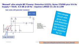
Ortofon MCA10 Moving Coil pre amplifier clone

I have an original MCA10 that uses two 1.5V disposable batteries.

I rebuilt the PCB because I wanted to use a rechargeable 18650 lithium battery. After being fully charged, it can be used for a long time, possibly for a week.

Some changes have been made to the parameters of the capacitor, which seems to be better.

This is very simple. If you are interested, you can DIY it. A schematic diagram has been provided.
1719454741412.png

267aa1bbf79dbf1ac28deac6da60a67.jpg


MCA10-B.jpg
MCA10-A.jpg

Unique Offer on Audio/Electronics

Due to my old age, I am clearing out the remaining inventories leftover from my previous business.
I offer the following items to any interested individuals with a desire to sell these items online. I accept any of your offer prices:
  • 260W power amp PCBs
  • Fast blow fuses and holders
  • Toggle switches, various sizes
  • 2- prong 6 ft. AC cords
  • Various heat sinks
  • Logic probe and pulser
  • Populated audio/electronic modules and many others ...........Make an offer!
Ideal business opportunity for an electronic hobbyist/audio amp DIY builder.


Sorry some pictures are too big to be posted!


-

Attachments

  • DSCN0117.JPG
    DSCN0117.JPG
    48.6 KB · Views: 134
  • IMG_20200613_181600.jpg
    IMG_20200613_181600.jpg
    351.4 KB · Views: 141

GRUNDIG R20 HiFi receiver

Sorry to bother you, but I have a problem with my GRUNDIG R20 HiFi receiver.
Namely, it spent a long time in the closet and my son decided to use it.
When switching on, after 10 years of use with the old speakers, the speaker on the right channel made a short circuit.
I understand that because it was stored in the garage for a long time (more than 20 years). To cut it short, my Darlington transistor G8004 burned out.
I replaced all output darlington transistors with new BDX54C / BDX53C and when they burned out (I was guiltyfor this) I also put new BDX34C / BDX33C.
I examined the correctness of the other transistors in the assembly and after some component replacements when adjusting biasing the quiescent (30 mV .... between test points x and y) current, the BDX33C exploded.
This happened when adjusting the quiescent current of the right channel to 30 mV.
I'm lost, now I install new darling transistors BDX34C / BDX33C (I have new BDW47/BDW42 .... this is for reserve).
I put new trimmers for adjusting ... 1kOHM.
I put trimmer to minimum and system operata .... no burning but I'm afraid to start adjusting more than 6mV.
My trimmer on the right channel was on maximum and I adjust biasing the quiescent to 6 mV
According to my calculation, the adjustment value should be a maximum of 9 mV and not 30 mV as recommended by Grundig in the HiFi Receiver R20 documentation.
I'm making a mistake somewhere with the settings or it's a problem that I don't see.
OK I can change the smaller trimmer but I'm not sure my darlin transistors will withstand 30 mV ..... as per the R20 documentation.
Please help if you can and thanks for your patience.
Best Regards,
BrankoPetra

Attachments

  • Output stage scheme.jpg
    Output stage scheme.jpg
    242.9 KB · Views: 59

Introducing My self

Hello everyone, I'm Jack Hicks, a dedicated professional in the DJ business with a passion for creating unforgettable musical experiences. With [number] years of experience in the industry, I specialize in delivering high-energy performances and seamless mixes that keep the dance floor alive. Whether it's a wedding, corporate event, or club night, my goal is to bring joy and excitement to every event through the power of music.
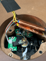
DBX 510 sub harmonic synthesizer

I've added a DBX 510 sub harmonic synthesizer to my setup.
I mounted it in a vintage DBX 118 box.

The description is below. It really adds a new level of sub bass and feeds a Carver and CSS sub.

It does need a bi polar +/- 15 volt power supply. Linear preferred.

I like it.

IMG_0795.JPG

DBX510.JPG


The 510 is a 500 series compliant subharmonic synthesiser that has been specifically optimized to enhance the low

frequencies in audio material. The 510 was designed for use in a variety of professional audio applications, including nightclub

and dance DJ mixing, theatre and film sound, music recording, sound design, live music performance, and broadcasting.

The 510’s patented Modeled Waveform Synthesis™ process builds a synthesized waveform using the wave shapes of the

original bass material, producing a new waveform modeled bass note exactly one octave below the bass in the original audio

signal. dbx subharmonic synthesis produces smooth, musical low frequencies that do not interfere with mid and high-band

information, even when the maximum amount of synthesis and boost are applied. The result is a low-end punch that people

really feel!

Using traditional EQ to enhance this extremely low frequency region doesn’t always provide desirable results and can increase

noise potential. Another problem is that the audio source may not have sufficient information in this low-end region to boost or

the mic used to capture the sound may not capture these extremely low frequencies.

The 510’s two independently adjustable bands of subharmonic synthesis (24 Hz–36 Hz and 36 Hz–56 Hz) provide the best

combination of smoothness and control. The SUBHARMONICS control adjusts the overall amount of effect applied to the

signal. The LF BOOST control can then be used to fill in the “gap” between the modeled waveform and the lower midrange of

the source, for a deep, smooth low-end response.
  • Like
Reactions: adason

Hey from Germany. Recently built my first set of speakers.

Hi there,

recently built my first set of speakers.

Speakers
FAST System with TB W8-2145, Dayton RSS315HF4
both in closed enclosures.
Surround with TB W4

No passive crossovers - all done in PC for active crossovers, EQ and DSP

DACs
DAC Topping DX3Pro
MOTU M2
Realtek Soundcard
maybe Multichannel DAC/Audio Interface in future

Software:
Windows 10
Voicemeeter Potato
Cantabile for VST Plugins for Crossover and EQ
REW
maybe CamillaDSP in future

Amplifiers:
Marantz PM11-S1
Fosi V3
SMSL SA.98E

surely I got many questions. At the moment struggling with different latencies due to running my signals through different DACs at the same time.


badie
  • Thank You
Reactions: GM

I did something different

I'm not aware of anybody trying this, I may even be the first...

I have an active system, my DAC is four ASUS Essence STX II PCIe cards.

My wife bought a cat and called it Dac, so I bought a DAC upgrade because fair.

So I bought four LHY lithium Battery power supplies, each stereo pair for my subs, woofers, mids, and tweeters are now (almost entirely) electrically isolated from each other.

I'm aware that battery powered DAC's often are reported to be superior, but four on four DAC's? It MUST be four times as good...

Previously they shared the LPSU I use for the Digital Crossover PC.

The benefit wasn't what I would call a "veil lifter" -after you move the crossovers into the digital stage before the DAC's, overall clarity is (almost) no longer an issue- but the improvement was apparent, I blind tested my (begrudging) wife by asking her to describe what differences she felt she heard -if any-from the test track I found for her, and hers concurred with mine.

Dynamic range was more pronounced, (her words: "the bass was more up and down, but like, wavy you know?") but more interestingly, the relationship between bass and treble had become less of a tradeoff.

I have preamplifiers and integrated monoblocks -a setup I encourage, as it can give different tonal properties to the same level of output- and with by turning down my preamp and turning up the power amplification just that smidge, it was like when I was a kid and managed to get the antenna on the radio to that exact sweet spot during the song I liked, I have a small amount of control over colouring, attack, I can change the timbre, if only somewhat.

This usually had the impact of the bass appearing too strong or weak, whenever I tweaked the treble (or the bass) I would also find the bass (or the treble) would often call out for some similar tweak, but now, they were no longer enemies, the tweeters were as amicable with the subs as the woofers would be.

I feel like transparency is greater, but it's probably just be being excited that it worked at all.

Turning on (and off) a fully active system with monoblocks and Multiple separate LPSU's dedicated to various components is like following the Minuteman launch procedures, I have some total of 30 odd buttons and switches to press and flick -one multiple times, several now only on occasion- in a set sequence, many of those reading will find this to be a total turn off, some, however have piqued interests...

My wife has (gracefully) allowed me to commandeer the lounge room on Tuesday nights, after the baby has been put to bed, but while dinner is being made I have to:

Switch all four new BPSU's from off to on.
Check their battery level -which is obviously apparent- and decide if I want to charge them, and if so;
Flick the four charging switches, plus turn on the one attached to the dedicated power board for their four wallwort power packs.
Press the power button to a second power board attached to the PC, and some various LPSU's for the preamplifiers.
Press the PC power switch (which doesn't work that first time)
Turn on the tweeter power amps
Press the PC power switch (which turns off the first failed attempt)
Turn on the midrange amps.
Turn on the PC (which works this time)
Turn on the woofer amps.
Turn on the subwoofer amps.
I still manually set the PC because my Linux skills aren't good enough to automate the steps I like.
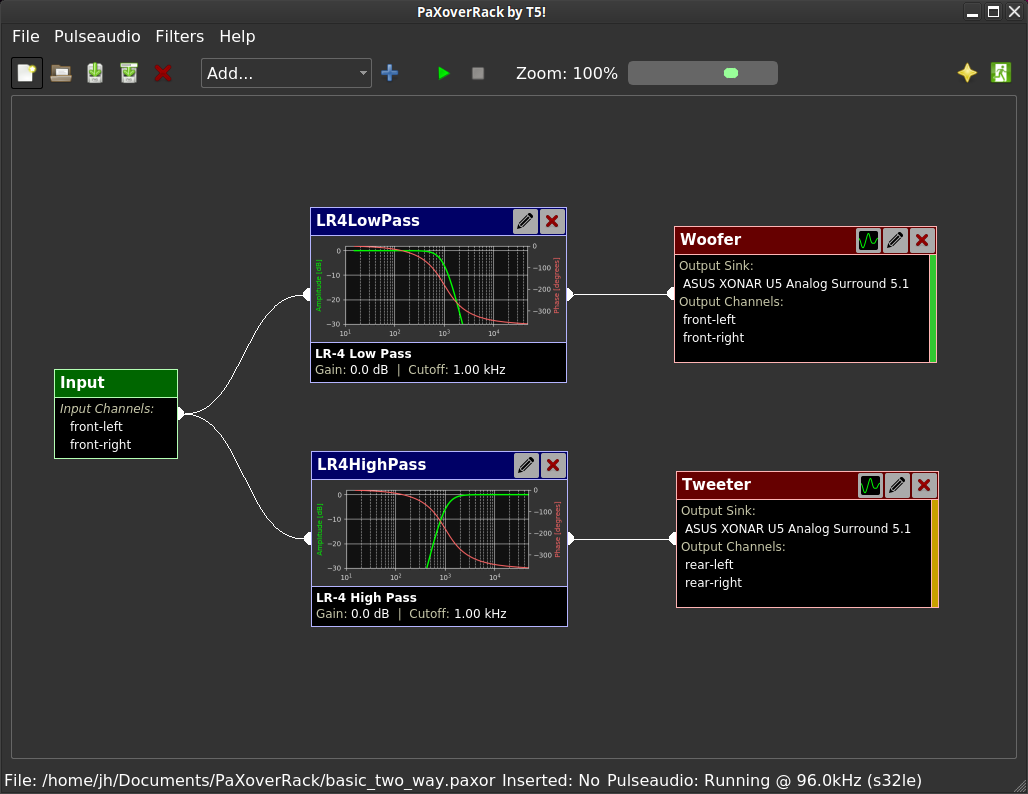
Run PAXoverRack, load the filter profile.
Run PaVuControl, do the -3db trick
Run Rhythmbox (I like it)
Eat dinner
Turn off the charging switches to the BPSU's, turn off the power board for the BPSU's plug packs.

If you're still reading, you may still be eligible to access some cash from the Australian NDIS scheme due to Autism.

TL😀R

But yeah, does anybody else here know anyone who's hooked up four BPSU's to four DAC's, or do I get to make up a name for it?

I want to call it the Bradley Configuration...
  • Like
Reactions: stv

Anodized aluminium push button with LED

I recently bought this push button " Anodized Aluminum Push Button with Red Light Circle 1NO1NC 250V 5A Ø19mm Black " from Audiophonics

https://www.audiophonics.fr/en/push-button/anodized-aluminum-push-button-with-red-light-circle-1no1nc-250v-5a-o19mm-black-p-8797.html

There are 6 pins and I don't know how to connect them in order for the LED to be switched on , when is powered and off when its not. Till now the LED remains on all the time.

I use the push button as a power button and I want to know when my system is on/off based on the LED. I am trying to connect directly the AC cables to the LED and then to the transformer.

Do you have any idea ?

Attachments

  • Screenshot 2024-06-25 094016.png
    Screenshot 2024-06-25 094016.png
    64.2 KB · Views: 175
  • Screenshot 2024-06-25 093948.png
    Screenshot 2024-06-25 093948.png
    167.8 KB · Views: 167

[3D Print] ACA Mini Feet (slide over the M4 Hex Standoffs)

I have a couple ACA Mini's I've built per the standard build guide and kit and although they sound fantastic, I wasn't a fan of the bare M4 hex standoffs as feet. They slide around too much and I was worried might possibly scratch whatever the ACA Mini was sitting on top of (which for me is typically the preamp). I decided to make some quick "slide on" feet out of 3D printed TPU material. The Thermal-Poly-Urethene material has a slight squishyness to it and has a little extra grip for that reason.

Attached is the 3MF and STL files you can use to 3D print yourself. Very very simple design. Print solid (no infill) by increasing wall count accordingly. They hold very tight on the existing M4 hex standoff and give the ACA Mini just a little more grip and protect whatever it's sitting on top of. You can remove them with a pliers if need be, but I suggest un-bolting them before attempting removal to avoid damaging the board (this are very snug fit).

If anyone wants some of these, I'm willing to send out the first two dozen or so sets for free if the interested party(s) covers the shipping fee (ideally in US only as shipping internationally makes it too expensive).
ACA Mini Feet Over Hex Standoff.JPG

ACA Mini Feet Over Hex Standoff_Sliced.JPG


20240706_002031.jpg


20240706_002052.jpg

20240706_002103.jpg

20240706_003856.jpg

20240706_003926.jpg

Attachments

  • Thank You
  • Like
Reactions: jt23 and Dennis Hui

Modifying prebuilt "book" crossovers?

Back story first.
Was building some party speakers from bits and bobs in the shed and some old boxes waiting to be junked. Found some cheap generic XOs on eBay and bought them because I didn't want to muck about on $100- speakers
These NOS from Jaycar
https://www.jaycar.com.au/3-way-speaker-crossover-1200hz-5khz/p/CX2621
I ordered 2 from the seller and using them now and they are "OK" with the drivers I'm using.
BUT
I just got a message from the seller that there had been a mistake in the listing and dispatch and he's sending me another pair.
I have some NOS and slightly used drivers in the shed I was contemplating making up some bigger speakers with.
I can't do anything about the orientation of the inductors easily or at all but I can change the capacitors for something better but is it possible to adapt what is coming to a third order at all? If so what compromises would I have to make?
I'd be using Zobles on the midbass and 50mm dome to get a reasonably flat impedance and using the first generation Vifa Neo tweeter on top.
It seems to me that these cross points are reasonable for the drivers I have, the Peerless dome is a nice even driver as is the Vifa Neo tweeter.
Woofer cross-over will then depend on how the top half works but I have a pair of 12" Carbon fibre woofers here that give good solid bass and I might just use those rather than buying a Peerless woofer.
Thoughts and advice please

Repurpose power transformer

Hi,
I have a 3 year old transformer with two secondary windings, 17V 3A and 7V 5A. It was used in a DIY linear power supply for a DAC and a Raspberry PI. I have moved away from that setup so I have this large transformer laying around....

Please give me ideas of what should I used it for. I was thinking about PSU for a cheap class-D board but the voltage is quite low (7V) and it is almost impossible to create dual rails for class AB amps at 15V. Also, it would be ideal if I can use the two secondaries or if I left one open, it probably waste of energy.

Best,
AP

Wiring help - 3 way crossover on 2 separate boards

I'm putting together the 3TDX center channel from CSS Audio. It's a 3 way design with 2 woofers, a mid, and a tweeter. The crossover is broken out onto 2 boards - one for the woofer circuit, and one for the mid and tweeter circuit. My question is this - what is considered the best way of wiring this up? Should the input to each board be connected directly to the binding post, or do people usually run one board to the post and then run a wire over to the second crossover board? They will be separated from each other by baffles on opposite sides of the cabinet, so my concern is that wiring them to each other will be more difficult and any potential future disassembly will also be harder. I realize it probably doesn't matter at all, I just don't want to find out later that something important slipped my mind. Thanks in advance.

CamillaDSP not understanding compressor

Hi,

I'd like to use single channel instances of the compressor processor, one in each output in the interest of protecting my drivers from errant bits caused by misconfigurations or crashes. It seems that with the included compressor the number of channels has to match the pipeline width which implies it must apply the same parameters to all (or the selected) channels in the pipe. I'd like to experiment with having different attack and thresholds for each type of driver (i.e. hefty subs can tolerate more abuse than delicate tweeters). I can see that putting a 1 to 1 mixer in each channel to narrow the pipe to one channel might do it but is that the only way?

Cheers, Louis

Allelectronics.com surplus is going out of business by end of August 2023

from their website
https://www.allelectronics.com/

After 56 years supplying surplus and new electronic parts and supplies, we have decided to call it quits. We expect to close our doors before the end of August, 2023. Our warehouse still contains lots of material which we need to move. Take advantage of our final clearance sale. This is the time to get some real bargains.​


I bought some of these PP film caps for my DIY FE-22 at 2/$1:
https://www.allelectronics.com/item...n-br-4-uf-250v-polypropylene-capacitor/1.html

Also bought the two versions of their 48V SMPS to try, but all those are probably gone by now.

Attachments

  • IMG_2808.jpeg
    IMG_2808.jpeg
    241.3 KB · Views: 217
  • IMG_2809.jpeg
    IMG_2809.jpeg
    385.6 KB · Views: 176

Can two high-side CCSes be paralleled?

Hello all,

As per subject line, in the case of a CCS based on a depletion-mode FET feeding a shunt regulator.

The FET has a max 150mA rating and my output stage needs 130 mA, plus the current into the shunt. So was thinking about paralleling two CCS cells, i.e. each FET with its own gate stopper and current set resistor, running at say 90mA each. Common drain connections and of course outputs tied together.

Being CCSes there is no risk of one hogging all the current no? The only gotcha I can think of is the two of them starting to oscillate sympathetically, but I'm not knowledgeable enough to judge if it is a risk or not. There surely are other considerations I don't foresee.

For what it's worth both FETs will be put on the same heatsink close together to keep them at about the same temperature.

Thanks in advance for any insights!

Joris

Car Audio, DIY to a low cost dang fine system the relatively easy way! (other car stuff is welcome as well)

Long time DIY car audio interest from dirt cheap to insanely expensive, on and off for over 50 years into this. First install was in my mothers 58 Bonneville coupe when I was 16, I am going to be 72 in May. Motorola 8 track and Sparkomatic 6x9's, yeah baby! Back then very few cars had systems, next one was in a 63 Belaire we used to cruise in the big city of Spokane and might the the only one with a system on the main drag whenever we could get up there as we lived 50 miles away in a town of 800. We were the sheat back then🙂

I am going to post up some things I learned over the years, most all from my car audio comp days, that can make it pretty easy to create a great sound stage in many vehicles, some are far easier than others, some pretty tough and I have little dirrect experience in that real though have coached quite a few "world champion" builds in most types of vehicles. And yes, there are those that know more than I do, some with a far longer history in competition, few have done what I did in a very short time, because I made a point to get to know some of the masters, worked with them on projects and paid attention.

I also sold a very high grade sound deadening product I owned and a secondary one I introduced to the car audio world as far as I ever learned that is, tens of thousands of happyt customers around the world. I will of course post my sound deadening recommendations followed by most all of them.

I know what I know and will not pretend I know more than I do, if anybody questions whatever I may post I will take it seriously and if agree will make it known and be glad to learn from them. I will also call out what I see as misinformed or pure BS.

Rick

3-Way active Horn Speaker (Monitor) for small rooms

Since a while now I want to build some speakers but I need some help with the concept. I'm listening to electronic music, sometimes hip hop and sometimes jazz music. You never get that feeling from small speakers so I'm definitely going to build horn speakers. Problem is my studio is quite small, about 15m² now and maybe 20m² in the future.

I like the concept of the Calpamos by Humblemadehifi because it uses the midrange horn down to 650hz. But I definitely want to use a multi sub system with 3 or 4 closed subwoofers. So I don't need a 15" woofer. A 12" woofer like the faital pro 12PR320 in a closed box would be better in the upper bass/midrange I think. But the PH2380 horn is too big for a 12" woofer (opitcally). Would this be a problem?

What should I do now?
- just use the 12PR320 with PH-2380+Faital HF201 (Calpamos with 12")
- use the 12PR320 with a smaller horn and driver combination (like mezzo Calpamos for example)
-or maybe build a horn for the 12" woofer (B&C 12PE32) and combine it with PH-2380+Faital HF201

I want to use an DSP with IIR and FIR filters. Best place for the speakers would be in the corners since the room is not that big. In the other two corners I'm going to put bass traps and in general I want to use 3-4 absorbers. But I'm not sure if get problems with early reflections using a constant directivity horn.

What do you think will work best in a small room? I'm open to other driver and horn suggestions. But most smaller horns just go down to 1,2khz-1,5khz 🙁

Would something like the Martion Orgon but using a multisub instead of corner horns be overkill in small rooms? I could use a 70-80cm tractrix horn with a 12" woofer for 80hz-800hz( I know not enough horn loading for 80hz), the BMS 4591 for 800hz-3khz with a 30-40cm tractrix and a 1" driver with 12-20cm tractrix for 3khz-20khz. Would this work or is it hard to build because of the two ways for 800hz-20khz?

Handheld Console / Raspberry Pi CM4 Amp

Hi All!
I'm incorporating an amplifier into a handheld console I've been developing. I'm trying to keep things simple as the rest of the board has been complex so trying to avoid the need for GPIO to talk to the amp. It takes the PWM signals from a raspberry Pi CM4 through the following driver buffer:
View attachment 1319011
Rather than the audio jack I then intend to run the signals through an amplifier (something like a TPA2012D2):
View attachment 1319015 The idea is I would then take the outputs to drive two onboard speakers but then when I plug in headphones to an audio jack this is rerouted into the headphones. This can be achieved using a headphone jack like the one in this image:
View attachment 1319014
The problem is the outputs from the amp are L+, L-, R+, R- so I'm guessing I need to use some form of op-amp configuration to convert this to a single-ended output. Then I can achieve the above since it will work for the headphones and the drivers.
Am I on the right lines here? Is this a stupid way of doing things? I'm fairly good with PCB layouts and Arduino stuff but for whatever reason when it comes to Pi's and amps that talk over I2C to set everything up my brain switches off.

Perhaps there's an Amp IC out there that offers Speaker Out/Headphone Out along with a detect pin for when the headphones are inserted? No need for any other MCU to handle things?

soft start for SMPS

I have built an M2 using a pair of Meanwell LRS units per side and it works great. There is an active thread on the upcoming F5m also using these supplies. A bigger amp like Stasis, Honey Badger or similar 100W+ amp might require a +/-48V supply and with a 4 ohm load we're up to a peak current of 12A per rail. This is available via SMPS and I can both afford it and lift it!

I have two questions:
1. Is it OK to just turn on a high current SMPS from cold and dump 10s of amps of inrush current into the downstream components? Is it deleterious to the health of the SMPS and/or downstream components (am I worrying over nothing?).
2. If it is not OK, then it appears there a need for a something to go between the SMPS unit and the amp boards, perhaps enabling the addition of some local capacitor reservoir for those who feel it beneficial. It would be great if there could be a sanctified version of a soft start board for these applications.

One of the potential advantages of the SMPS is that it can be cheap and although expensive solutions exist with soft start, speaker protection etc., this choice negates the cost benefit. And as Nelson Pass has astutely noted; we're cheap.
😉

Maybe if you take the store soft start circuit and put the SMPS output across AC1 and AC2 and the load across XFR1 &2, leave D2 & D3 open, short D1 & D4 and choose appropriate high current /. voltage versions of the relay and capacitor maybe it does the right thing, but I really don't don't know.

As a cut & paste artist / solder slinger I am aware that I don't know what I don't know, but it appears that this simple (?) module capable of options for different voltages and current and bipolar supplies would be of wide utility given the increasing number of SMPS based audio toys.

bridge amplifier with current sensor

Hi everyone.
Is it possible to make a bridge amplifier coexist with a current sensor, like husband and wife after many years?. 🙄😀
the purpose is to create an intelligent network for feedback and correcting the current when the speaker impedance changes with frequency.
I read up on current sensors but none of them satisfied me completely then one day Mr ELvee (member of this forum) was kindand he pointed out his circuit to me:
https://www.diyaudio.com/community/...ransformer-based-circuit.356221/#post-6247241
the heart of the sensor is the clamp but for a feedback network a small toroid whose enamelled wire winding has the task of detecting is more appropriatethe signal
generated by the speaker current which is amplified by the two transimpedance opamps , everything else is useless. what I like about this system is the absence of contact and no
resistors in series with the speaker.
I subsequently thought of an alternative which you can see in the photograph. to do a quick test and verify its functioning I used 15 (15 is not a fixed number, it varies according to needs) small plastic toroids (therefore magnetic permeability equivalent to air, no ferromagnetic core) arranged in a row to capture the maximum intensity of the magnetic field.
the windings are connected to each other to form a larger one, a single layer of turns for each toroid. you can see it in action in the first attached video, the terminals are connected directly to the oscilloscope probe so no amplification with opamp.I used a 20-20khz sweep,
I can't tell you what the volume was but I'm sure it didn't exceed 50%. the amplitude of the signal seen on the oscilloscope is adjusted on the volt scale.
to create this type of amplifier I thought of the scheme shown in the second attached video. in the simulator, I used a transformer as a current sensor because I couldn't use anything else and instead of the speaker I used a variable trimmer. apparently if the circuit is applied in reality, it doesn't work and this is a real shame.
this was stated by people accustomed to chewing electronics every day. Mr ELvee also advised me against going down this road, so I'll stop here.
however it seems right to me to share what I have done and the information collected, in this forum there are many brilliant minds who can express an appreciated opinion.

Attachments

  • Sweep forum.mp4
    14.9 MB
  • current sensor.jpg
    current sensor.jpg
    133.4 KB · Views: 156
  • bridge amplifier + current sensor.mp4
    2 MB

DIY ACA Mini twist - help?

I built the ACA Mini almost clone (many thanks to Papa and Kevin for that). It is a truly great sounding little amp. I love it. So I wanted to go a step further and make the same thing in a proper chassis that I could give to my daughters.
FWIW I laid out my own version of Mini ACA. And I sent out for boards and got them back. I felt I could do better so re-did it and also added a TL071 unity gain inverter to feed a bridged mono-block arrangement.
Does anyone out there want to cooperate on this, i.e. check the schematic and layout and provide suggestions or blessings? I'll probably get 10 boards made (again) so would share pairs at cost. BTW, these are mono boards with JST connectors (or soldered wires could be used) designed to go in a chassis and use conventional heat sinks. Is anyone interested in helping with an engineering review to be sure these turn out as they should? Let me know. I'd like to order the next round of boards soon. Thanks. BTW, I'd be happy to share the schematic and layout for review. Please PM me if interested.

Speaker Repair Question

Folks:

I'm looking for some guidance on a speaker repair project. My daughter and I recently built a chipamp-based integrated amplifier for her (a father-daughter project which was great fun). After a couple of months of use, one of the channels on that amp blew (entirely my fault; I stupidly misread the BOM and used a couple 1/2W resistors, not 2W resistors). My daughter told me that when the amp released its magic smoke, she also saw smoke coming from the rear port on one of her PSB Alpha B1 loudspeakers. The amp has been repaired and I'm ready to tackle that speaker.

The blown speaker measures 0.2R across its terminals. The other speaker measures 3.8R across its terminals. My first question: how do I determine what to repair/replace in the blown speaker? Notably, I haven't tested the presumably good speaker yet. I don't have any test equipment other than a few multimeters.

My second question: regardless of whether the problem with the blown speaker lies somewhere in its tiny crossover, this seems like a good opportunity to upgrade both speakers' crossovers. A closed thread ( https://www.diyaudio.com/community/threads/psb-alpha-b1-internal-pic.137546/#post-4542271 ) provided the values of the caps and resistor used in the PSB Alpha B1; should I just install better quality equivalent-value parts?

Your advice is appreciated!

Regards,
Scott
Projects by fanatics, for fanatics
Get answers and advice for everyone wanting to learn the art of audio.
Join the Community
507,619
Members
7,880,128
Messages

Filter

Forum Statistics

Threads
405,871
Messages
7,880,128
Members
507,619
Latest member
Yahweh1x