Rectifier Diode Replacement

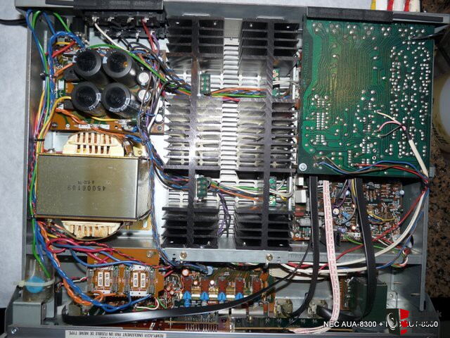
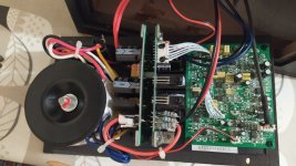
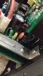
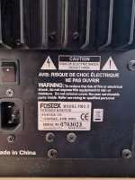
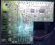
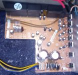
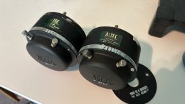
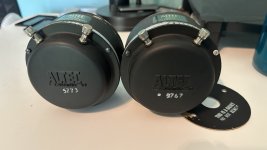
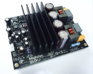
Been a while since I've been here, just looking for a bit of verification on my current problem. I have an Auna Concept 620 which has been acting up lately, a lot of noise on the channels at times, audio just not coming out at random, other times audio being extremely quiet even with the sub volume at maximum, that kind of thing. I'm fairly certain the problem is with the 1N5404 rectifiers and considering they are on the edge am wondering if I should replace them with some 1N5408s to handle things better or if anyone could suggest something else? My only focus is with building something that is extremely robust - specs mean nothing to me if I won't have an audible difference.

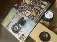
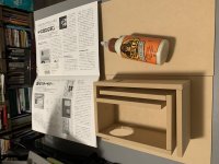
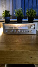
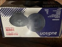
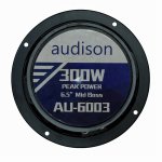
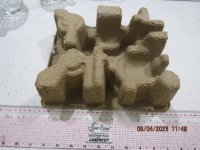
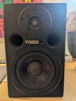
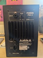
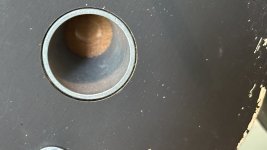
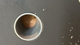
Years ago I did some major recapping work on the sub where the primary capacitors blew out (I wasn't surprised to see this when I saw how severely under spec they were) so those got replaced with 2x 25v 125c RS brand capacitors and all other caps were replaced with Rubycon and Nippon Chemi-Con 105c so I know all of those caps are good but to be sure I did also inspect them, no leaking or bulging I can see. Any extra input is appreciated, I've attached a few images of the patient.

EDIT: On another note why is it the text size is appearing like it is set to extra large on the forum and it won't change when I select other sizes?

Attachments

  • IMG_20240731_001846_801.jpg
    IMG_20240731_001846_801.jpg
    737.3 KB · Views: 129
  • IMG_20240731_001909_845.jpg
    IMG_20240731_001909_845.jpg
    727.2 KB · Views: 131

For Sale Tamura A-4714

Selling 1x pair of Tamura A-4714 line out transformers, in excellent condition

Prim: 5K 60ma
Sec: 600 (300 split) / 6 ohm

Interesting transformer that can be used as a line output transformer or as a regular output transformer to drive a speaker or both!

SOLD

Attachments

  • tempImagepz8Sye.gif
    tempImagepz8Sye.gif
    1.7 MB · Views: 68
  • tempImagewHQJad.gif
    tempImagewHQJad.gif
    1.6 MB · Views: 66

For Sale Altec 806a drivers - pair

parting with this pair of Altec 806a 16 ohm drivers. They sound great and are solid all around. Pulled from 9844 monitors. Diaphragms are replacements from Midwest Speaker. DCR measures 11.1 for one, 11.0 for the other.

SOLD

Attachments

  • IMG_2736.jpeg
    IMG_2736.jpeg
    206.8 KB · Views: 115
  • IMG_2737.jpeg
    IMG_2737.jpeg
    187.2 KB · Views: 89
  • IMG_2738.jpeg
    IMG_2738.jpeg
    212.3 KB · Views: 80
  • IMG_2739.jpeg
    IMG_2739.jpeg
    196.9 KB · Views: 85
  • Like
Reactions: cibo and twitchie

FreeCAD tips and hacks for cab design

Things that we find in the program that can save some head scratching, Please allow me to start with these three for sheet material:

1. Start your drawing away from the axis central dot and, for even more flexibility at a future stage of development, away from the axis lines as well. Use the distance constraint set to 0mm to bring it to the axis once the panel is drawn. This allows placing a fillet on the corner that will be on the axis centre as well as future movement of the panel

2. Make the first base panel larger than needed. You can always bring the excess in without FreeCAD getting its panties in a twist. But adding on later to increase the area will create new lines in the model, and this will set a limit for fillets in that area, plus too many other reasons to recount here

3. Let's say the material is 16mm or 32mm, and you are trying to set a 16 or 32mm radius on the edge. FreeCAD will throw a hussy fit. You can do 15.99 to get close, or 31.99mm. 15.9 or 31.75 is better as you can find that router bit at a good price of Ali or eBay

4. Drawing in sheet material is best left to a tested design. For prototyping, it is more efficient to create a base body and carve cavities into that. These will represent air volumes, ports and such. The drawing is done in a reverse outline, where you draw the profile of the cavities on a side panel. Then carve that out, and you will be left with a sold set of walls sans the sides. These are added on after finishing the interior work. It is very possible to do the whole inverse outline as one sketch only, which again is perfect for prototyping as all the objects are continued within one sketch and changes on the fly do not cause FreeCAD any upset. Once the model is complete. Panels sizes can be just pulled off with some simple calcs and redrawn into a new file as a mature panel design. This is quicker than having to delete a lot of objects to go back to make a simple change. Prototyping a 3D model in this manner leaves the most options open for changes further on
  • Like
Reactions: stv

Extreme 1543 DAC

So I was searching for some transformers and I stumbled across an Extreme 1543 DAC Kit from diyhifi.net. It looks like I purchased it in 2008 and also bought the upgrade to 8X 1543. I found the PCB populated and I don't think I ever finished the assembly. I can post some pics of it tomorrow. Here's the schematic of the PCB

Is there a way I can feed this an I2S signal?

Attachments

  • TDA1543DAC US[1].GIF
    TDA1543DAC US[1].GIF
    177.4 KB · Views: 143

Workbench sub

Guys, help me choose a good workbench sub. One that can be used to test out different ideas and things. Interested in operating range down to low 30s and one that doesn't require a huge box and fits on my CNC

A high performance 8" would be perfect. Something that is well sorted and fairly well known. Also, something that suits BR and TL cabs

I have been looking at this one as a candidate for a bench sub. Any other promising 8s?
https://www.wagneronline.com.au/sb-...dio-speakers-pa/sb23mfcl45-4-64590/976215/pd/
  • Like
Reactions: Booger weldz

Looking for a pair of waveguides: QSC PL-000446GP or B-52 PHRN-1014 or PRV Audio WG35-25-B

I'm looking for a pair of waveguides of the following types:

QSC PL-000446GP (horn of QSC HPR152 loudspeakers)
PRV Audio WG35-25-B
B52 PHRN-1014

These waveguides are the ones that were used in Econowave Deluxe from Zilch. The PRV and B52 clones were available in the past at Parts Express, but not anymore and the original QSC not anymore available as spare parts by QSC.

Preferably from the Europa Union (I'm located in France). Please make offer including shipment to EU.
  • Like
Reactions: IamJF

Re-center spiders in Ohm F: using DC voltage

In an effort to stiffen the spiders to a new, correct position on my Ohm F's, I'm thinking of applying DC voltage to each driver to move the spider into position and then apply ingerdients to re-stiffen them. This may be for a few days.

I see 1.8V, 0.31A is required to do this.

Is it fine to leave DC voltage to the voice coil for an extended period?

NEC AUA-8300E any good?

I was able to get from Canada a NEC AUA-8300E integrated amp and Nec 8300 tuner.
Both pieces were never sold in the USA. The tuner and the amp are located with my tech for a recap, I know the tuner is a good performer, but I dont know anything about the Nec 8300 amp. So I am on the fence about spending any money on it.
What do you guys make of the integrated amp ? Any good ?
Can someone review the schematic and see what is inside ?


NEC AUA-8300E Stereo Integrated Amplifier Manual | HiFi Engine

some pics from the web

417711-35b6c4da-nec_aua8300e_amplifier__aut8300_tuner.jpg


An externally hosted image should be here but it was not working when we last tested it.

Can't figure out how to read this impedance graph

Silver Flute W17RC38-04
I have never seen an impendence graph like this.
How do I read this? I am trying to trace it to see if its a viable choice for a build I am considering. Basically a budget 2 way build I could give away to friends.
How does the "V" translate to ohms?​

Attachments

  • Screenshot 2024-08-11 173854.png
    Screenshot 2024-08-11 173854.png
    39.4 KB · Views: 141

HiVi RT2C-A for sale

Too many speakers already (not as many as Cal 🙂). I do not plan to use these right now, so instead of sitting on shelf collecting dust, someone can use them. The are lightly used, in great shape, just some residual glue on edge or back. Make offer, pay shipping in us (~$19).

Attachments

  • 1000032529.jpg
    1000032529.jpg
    633.6 KB · Views: 64
  • 1000032530.jpg
    1000032530.jpg
    650.5 KB · Views: 66

Greetings from atherton

Hi all am mick from atherton nr manchester uk
Am 57 currently having time off work
I live wi mi gf deb and her 2 sprogs
Av geet a Frenchy biggest av evr seen called buster
Av been into audio stuff for last few year
Been stalking these forums for a while gathering info here and there so thought better join av geet 27 technics separates a few pioneer and a few sony just restored a sony str 11l
Currently trying sort a str 7025 out
And lookin for a service manual
Looking forward to joining in the discussion
Thanks for reading
Mick

Attachments

  • 20240730_212530.jpg
    20240730_212530.jpg
    413 KB · Views: 40

Analog xo, LP only, stereo in > 3 outputs or more?

If known, please suggest any DIY or plug'n play. For a 4-subwoofer distributed array. Already familiar with the Ashly digital.

Analog subwoofer active xo, requires only low-pass

Inputs:
Prefer balanced XLR, not a deal breaker
2-input (stereo), sum to mono

Each output:
3 outputs minimum, prefer 4
Prefer XLR balanced, not a deal breaker
Continuous phase 0-180 mandatory
Selectable pole, require only 70 Hz minimum up to at least 140 Hz (prefer 200 Hz)
Parametric EQ nice, not mandatory
Prefer selectable 12/24 dB, maybe 12 dB OK

Looking at building an easy to build Distortion Analyser adaptor for my Oscilloscopes.

Hi everyone,
I'm planning on building a Distortion Analyser adaptor for my two Oscilloscopes, using a design from an article I found online, the circuit of the Distortion Analyser looks relatively easy to build, and uses fairly common NPN bipolar junction transistors, should be a fun and useful test gear build project, I'll post a pic of the schematic later on.

Are these genuine Audison?

HI
I saw these Audison's mid-bass drivers couple of days ago for a very reasonable price but I couldn't find anything online about them.
I wondered if these are genuine Audisons or if they are fakes
If anyone has came across these and knows anything about them, I appreciate the help.
Thanks

Attachments

  • f15e7ef5-307a-4451-bc80-24c521b1a366.jpg
    f15e7ef5-307a-4451-bc80-24c521b1a366.jpg
    150.7 KB · Views: 70
  • dbdc72457eaeb4bd02f076425fb2d6664ed62855_1629015626-01.jpeg
    dbdc72457eaeb4bd02f076425fb2d6664ed62855_1629015626-01.jpeg
    104.5 KB · Views: 69
  • 54422c65bed916481da603add2a51df92ea635ad_1629015632-01.jpeg
    54422c65bed916481da603add2a51df92ea635ad_1629015632-01.jpeg
    110.6 KB · Views: 69

Acrosound TO-310 Schematic Bypass Cap Values?

OK just to clarify, I want to build this amp using some vintage Acrosound TO-310 transformers I picked up and want to use their vintage published schematic. I'm not asking for a review of the overall design or suggestions on changing to another "better" topography. And while I feel I have a good understand of single ended amps, I'm just starting to understand and work with push pull stuff. These bypass cap values don't make sense to me.

So again, I'm simply trying to understand their suggested bypass caps. They have a 1K resistor being bypassed with a 250uf cap which is good to 6.4hz, I get that one. But then on the output tubes, they have a 250R being bypassed by a 100uf, which is only down to 64hz. I am clearly missing something here, as that doesn't make any sense to me.

This design was used by many people and tested well with this iron, so I don't think there is a problem with the design, just my understanding of it. TIA

6V6-acrosound.png


acro-310-test.png
  • Like
Reactions: huggygood

Thoughts about egg carton type surfaces

I know that egg cartons themselves don't do much: but I was unpacking some IKEA furniture this week and I'm wondering if these or something like these could be used as a diffuser panel by gluing several of these to a sheet of stiff cardboard using PVA glue and if they would work to any degree?
I'm not sure that SWMBO would actually allow me to screw such panels to the ceiling.
Could they qualify as "Art" if I got the grandkids to paint them in bright colours and hung them on the walls?
PVA and sample pots of paint are relatively cheap
Usable or just a dumb thought and I need to chuck them in the compost?

Attachments

  • IMG_2545.JPG
    IMG_2545.JPG
    88.1 KB · Views: 140
  • IMG_2547.JPG
    IMG_2547.JPG
    81.1 KB · Views: 127

Simple battery current probe

Have you ever wanted to measure the current consumption of a battery powered device, but found that you need two hands to hold wires against the battery, and your other two hands to hold wires against the battery contacts, leaving you with not ernough hands free to operate the device itself? Here's a way to reduce the required number of hands.

The probe itself is made from FR-4 double-sided copper clad board, nominally 0.2mm thick (actually 0.25mm including the copper layers). At that thickness it's easily cut with scissors, and very flexible. This stuff is cheap, but not widely available. I found some on Ali Express.

After cutting it into a long shape narrow enough to fit against a battery contact, I carefully sanded the edges to make sure no copper bridged the two sides. I soldered a wire to each side of the board, making sure not to bridge the two sides with solder, and attached a 4mm banana socket to the other end of the wires, for connection to a multimeter or oscilloscope. Here's what the completed probe looks like:

DSC_0851.jpg

And a closeup of the tip, where you can just about see the individual layers of glass and copper:

DSC_0853.jpg

It's so thin that it can be slipped between a battery and a contact, diverting the current through the wires instead. Here it is inserted into the back of a DE-5000:

DSC_0858.jpg

DSC_0856.jpg

And finally a shot of using it with a multimeter to measure the actual current consumption of the DE-5000:

DSC_0859.jpg

If you're curious, the DE-5000 uses 20mA when measuring a capacitor (as shown in the photo), 16mA when idle, and a mere 2µA when off.

  • Poll Poll
What is your headphone out jack size preference

What is your headphone out jack preference 1/4" or 1/8" or 2.5mm

  • 1/4" (6.35mm)

    Votes: 27 87.1%
  • 1/8" (3.5mm)

    Votes: 4 12.9%
  • 2.5mm

    Votes: 0 0.0%

I've always defaulted to making the output jack on my headphone amp builds 1/4" and suddenly wondered whether there is a genuine reason to use up so much real estate when a 3.5mm would do the same job.

So as a headphone user, what size output jack do you prefer, and why?

Updated Pass A40 Design

I've been having a look at Nelson Pass's A40 Class A design, that originally appeared in Audio magazine in the late 70's. I have done an update of the design that eliminates the tantalum capacitors and the need for the unobtainium Llambda power Darlingtons originally used in the design. This comes at the expense of discrete Darlingtons, but the ability to choose zippy updated bipolar driver and output devices, as well as being able to optimize the driver termination resistors may make up for the added complexity. All the parts should be available from the usual suspects. I'll post a prelim schematic when things quiet down for me a bit (3-5 other projects in the works). Of course I'm posting with the full realization that this is not strictly a Pass design any more, as so many aspects of the design have been changed.
  • Like
Reactions: rmfar

Eurotrip/parts search

Hello friends, I am starting a trip through some cities in Europe and I wanted to know if any of you know about electronics sales businesses for our DIY hobby, such as selling capacitors and resistors, even valves, etc. The cities that I am going to visit are Valencia, Madrid, Dublin, London and Edinburgh, any information is appreciated. In my country some spare parts/valves are quite difficult to find, and if they are available, sometimes it is at exaggerated prices. That's why I wanted to take this travel opportunity to take some things home. thank you very much friends

I have two Audioline 15W powered studio monitors, one needs servicing, need schematics for them.

Hi everyone,
I have a pair of Audioline 15W powered studio monitors, one of them needs servicing to fix intermittent distortion, I was wondering where I could find schematics for them online? they have internally mounted solid-state amplifiers in them, I'll see if I can post the model number later on today.

G.E. BA-5A audio delay line LTspice and other info

I happened to see the General Electric BA-5A limiting amplifier and that it uses an analog delay line to get the control voltage ahead of the signal, so nothing above a set level can get through. Reading the material on the web and in a book here, I started playing with LTspice to come up with the delay line using the same capacitance and induxtance, and tweak it for flat frequency response and also determine the time delay at various frequencies. It's by no means a complete treatment but there are three transformerless models and two with transformers. The transformers are not well-modeled, but I hope it will be of interest. Note that the book mentioned has just about the full theory section from the manual for the instrument as well as a great schematic. references are included in the document attached.

Because I prefer tube and other analog gear, and note that just about all compressors and limitiers have a finite attack time that can allow some excessive peaks through, this one is very interesting. I'm probably wrong about a lot of this stuff and just trying to understand it.

Attachments

Maybe a better way to cascade Linkwitz-Riley filters...

Been pondering IIR crossovers some more...always dangerous for me, being the die hard linear-phase xover dude I am...lol

Many are no doubt familiar with Linkwitz's cascading strategy found at https://www.linkwitzlab.com/frontiers_5.htm#V
First from that link, it's shown how a parallel 4-channel topology has its issues, and that cascacading is a definite improvement.

1723226901113.png


Then next, the bold text in the snip below describes adding an all-pass to the SW (sub) channel based on the W channels low-pass frequency,
improves response further.


1723224195493.png


I think there is a better way, and not much harder to implement, ......particularly if you have an open-architecture processor than lets you place filters in series as needed.

Cascading high passes is retained....but the recommended SW all-pass gets dropped,
in exchange for putting all the low-passes used in higher channels, in series after a channel's principal low pass..

So for example, using the W channel which has a principal low pass at 200Hz. It gains a second low-pass in series at 2000Hz (The M channel principal low-pass).


1723225076607.png


With the above flow put into a processor, here's the measured T+M+W+SW summation.

1723225853697.png


So zero ripple.
With no level adjustments, delays, or all-pass, on any channels.

Maybe there's holes in this.....i dunno..
again, i'm NOT an IIR man 😛

I figure the ripple free results can most likely be achieved through the use of more all-pass filters in series on the channels, akin to the low pass strategy I used.
But I'm like why bother with that?
When the low-pass strategy is so straightforward and simple....

Folks who do know IIR... please correct any/all of this if I'm barking up a tree (again LOL) ...thx, mark

Lase LF18-3600

Is anyone using these drivers? I have 4 loaded into 176l 30hz tuned reflex cabs.
The measured response is poor with a huge peak at 65hz and low output below 45hz but I believe the dsp in the plate amps I am using is the issue, once I get a proper amp I’ll measure them again.

Product Specifications:
  • Nominal Diameter: 18"
  • Power Handling (RMS): 1800 Watts
  • Power Handling (max): 3000 Watts
  • Impedance: 8 ohms
  • Frequency Response: 30Hz to 1,000 KHz
  • Sensitivity: 97.5 dB 2.83V/1m
  • Xmax : 13.5mm
  • Voice Coil Diameter: 4.5"
Thiele&Small Parameter:
  • FS: 41 HZ
  • Re: 5.5 ohm
  • Qms: 9.7
  • Qes: 0.41
  • Qts: 0.37
  • Mms: 247.4G
  • BL: 29.3T-M
  • Sd: 1216 cm2
  • Vas: 124.4 L
  • Weight : 42.2 Lbs(19.14Kgms)
  • Shipping Dimensions : 20.5" x 20.5" x 17.5"(533.4mm x 533.4mm x 457.2mm)

Soldering Iron Bit Problem

Just looking to see if anyone has had similar problems to me and if there are any experts that can offer advice. I’m using .5 mm Weller solder and a Weller WE1010 iron with a 1mm needle point bit.

The problem is my bit keeps losing its wetting and it oxidises and then will not solder properly. I’ve tried it at 350C temp and then 395C but it is still problematic. Any ideas? Thanks

IMG_0026.jpeg

Attachments

  • IMG_0024.jpeg
    IMG_0024.jpeg
    29 KB · Views: 110
  • IMG_0022.jpeg
    IMG_0022.jpeg
    695.5 KB · Views: 105

ADAM A7 Service Manual (including schematics) needed

Hi,

Have a fault with one of my Adam A7 monitors. Upon a visual inspection of the PCBs I have discovered a burnout component which I would like to verify. It's a small flat orange circular component which I think maybe a capacitor.

I would also like to get to the bottom of what has caused the component to "fry".

The PCB I am referring to is the right hand one mounted vertically as pictured (with white connector).

Any advice or tips people?

Thanks

Attachments

  • IMG_20240809_220450.jpg
    IMG_20240809_220450.jpg
    300.7 KB · Views: 142
  • IMG_20240809_220730.jpg
    IMG_20240809_220730.jpg
    237.7 KB · Views: 99

Alpine 7269 schematic

Hello I was wondering if anyone has a schematic for a Alpine 7269 cassette deck . This is a deck that I've been using in my 83 jeep CJ for years and it finally packed it in . I would just replace it with a newer deck but that would require cutting the dash and I want to keep the stock retro look and function. Turns out these early made in Japan Alpines are starting to become more valuable so figured I would see If I can salvage this one . thanks for any assistance Roger

Greetings

Greetings 🙂.

I'm new to building speakers and associated electronics. Just last Friday I fired up an Econowave I researched and built (inner damping and outer finish still to do) with assistance during wood sawing, routing and drilling from a friend. I am now in the process of putting together an amplifier.

Where to place high-pass filters?

Hi. This is probably a dumb question, but I'm cobbling together a pair of presence speakers using existing drivers and parts I have lying around.
I want them to operate only from 500Hz up, and I want to cross from the midrange to the tweeter at 2kHz.
I have a pair of existing existing 500Hz and 2kHz high-pass filters already built up from a different project few years ago, so should I take the 2kHz filter feed to the tweeters directly from the amp's full-range output, or daisy-chain it off the 500Hz filter?
Thanks.

New ldovr.com power modules (LT3045/LT3094/TPS7A4700/TPS7A3301)

Dear DIYers

Recently we have released a new revision of our regulators, please take a look

1. New Revision of Dual LT3045 PCB, 0-15V, 1A.
Now it is a bit smaller(24mm x 40mm), Heatsink friendly and can be paralleled for lower noise and higher current output.

3045-1AG-1200c.jpg3045G_heatsink.jpgparalleling_multipleLT3045-1200.jpg

2. Single LT3045 regulator board with fixed output 0-15V. 0.5A - same footprint (24mm x 40mm)

3045-0A5-1200c.jpg
3. Single LT3045 regulator board with configurable output 0-15V. 0.5A - 24mm x 40mm, the output voltage can be configured by DIP switch

3045-0A5M-1200c.jpg


for more details please visit www.ldovr.com

Best regards
and
Happy New Year

Hello from Slovakia

Hello everyone,

I am a technical university student studying software engineering. I do not have any proper education in physics or electronics, except for few courses, but I am more than willing to learn and take notes. Last year I have picked up electronics as a hobby, mostly digital circuits, but my interest in analog circuits is growing and is currently what I drain majority of my free time into. I am a proponent of open source and open hardware so I am looking forward to sharing my finalized projects with you on this site. Thank you for your time and I hope that I will fit into this community.

Greetings from Slovakia, enjoy your summer.

To display the album art of the playing music from the Tidal desktop app (windows) on an Arduino LCD.

I use TIDAL to listen to music. I don't use a dedicated network player, I use a Windows-based PC, and I use TIDAL's desktop app for Windows.

Like a typical network player, I wanted the case to display the album cover art of the current track when playing music from the TIDAL app. I used an Arduino and a 3.2-inch LCD to accomplish this.

Login to view embedded media
Since there is no official way to get information about the currently playing track in the TIDAL desktop app, I used window hooking to get the song title and artist, and then used this information to call the TIDAL API to get the album's cover art.

The obtained image is sent to the Arduino using serial communication. The Arduino displays the image received from the serial communication on a 3.2-inch IPS LCD. It's a slow process, but it's acceptable.

20240811_122135.jpg

Right way to simulate the EMI Filters? and load network

I was just trying to simulate the EMI filter now considering the Brookes Stability criterion had considered the values for the common choke with about 60mH.

Now was just doubtful about that is it right way to do the simulation with the loads. As I see differential version seems fine but common mode which is bottom circuit is something Im doubtful about.

the green curve is the differential mode output measured across R8 in the top circuit

the blue curve is the common mode output measured between the mid point of R2 and R6

Attachments

  • emi filter.PNG
    emi filter.PNG
    28.7 KB · Views: 74

Hi Everyone

Just thought I would start an introductory post, anyway, I just returned to the diyAudio forums after some time, I'm a long-time diy electronics hobbyist, I started out in diy electronics when I was 13 years old, I'm going to be turning 55 years old this month, and I still have the same level of interest in diy electronics as I did when I first started, I am currently living in Darwin NT Australia, it is a real pleasure to be a member of the diyAudio forum.

Greetings from Denver

Howdy folks, Big Willy here close to the Rocky Mountains. Happy to be here! I have some electrostatic speakers that I am trying to get sorted. Thought I would join and see what's what. Also interested in exploring Stax headphones and tube sound. If anyone has recommended electronic repair services close to Denver/midwest, please do share below in the comments. It is very hard to find good techs these days! Love the people who keep our gear alive and well.

Best,
UncleWill
  • Like
Reactions: rockies914

OB woofers query

Last month somebody posted a query on OB woofer mounting.
I've been itching to make another set of largish OB speakers for while utilising some old school Road Thunder 15" i have combined with the Jaycar 12" that are really only suitable for OB use [ Qts of 1.7] and I'm intrigued by the way they described the woofer mounting.
As per my attached sketch.
Blue driver being the Road Thunder and Red being the cheap Jaycars of which I now have an even half dozen but was going to use a quad but could use three per panel depending on what mids are used
My query is this. Is there a "Best Fit" set of angles for this way of adding in my big woofer?
I'd already contemplated a second box sitting beside the tall panel but this might work best for me.
I've already decided on angled wings and a 600mm wide baffle to suit the panels I have and I thought 300mm wings would work reasonably at 45degrees

Attachments

  • IMG_3084.JPG
    IMG_3084.JPG
    78.7 KB · Views: 83

Best used budget Stax system?

Really curious on the fuss for electrostatic ear-speakers. I have a pair of electret headphones (Stax SR-30) just to dip my toe in. All this talk about how much better true electrostatics are makes me curious. A few questions:
  • Does anyone have any thoughts on the best used Stax headphones?
  • Is there a better deal out there versus the SL-300 as an entry set of headphones?
  • Is there a difference in the sound of normal vs. pro bias electrostatics?
  • Any thoughts on the (now ancient) SR-5?
  • Tips for buying used electrostatic headphones? I believe that asking for sound balance is important.

Greetings From Seattle

Hello, Ben Smith here from Seattle. Long time audioholic beginning with a Marantz 2216b in 1979 - yes, budget friendly stuff 🙂 I've been lucky enough to move into Bel Canto DAC and amp, Meridian transport, Sota table and Vienna Acoustics speakers. More to the point of this forum, have built a couple of Bottlehead amps and am trying to design a 101D preamp as well as restore an APT Holman preamp. My other main distractions in life are photography and cycling, road and gravel. I'm also the winemaker, owner and bottlewasher of a small Seattle winery.

6.5” full range dip at 6K

Please feel free to move if better posted elsewhere.

Is this the expected handoff problem from mid to whizzer phase plugged with this driver?
Design problem(s)?
Recording/measuring error(s)?
All the above?

Drivers DA PS180-8
Hemisphere baffle internally lined with LOTS of silicone to minimize resonance problem(s)
Cabinet 42 liters/1.5cu ft good amount on cotton batting but not over stuffed
Rear ported (tuned at 80Hz) 4inch diameter 1inch length

IMG_7951.jpeg
IMG_7952.jpeg
IMG_8013.jpeg

Replacement tweeter for Fostex PM0.5

Hello all, thanks for having me in the group.

I'm after some advice on replacing a malfunctioning tweeter on a Fostex PM0.5 monitor.

It's just a single tweeter on one of the monitors that isn't working. I've done some online searches to find a replacement tweeter but it's a minefield for someone with limited understanding on these issues such as myself. I've got so far as to figure out its .75" diameter & 30watts.

Would this work?

https://www.cricklewoodelectronics....88KNYYez7FhrI7nkolfaaSDLS16M8J64aAjIMEALw_wcB

Any advice on which tweeter would fit/work correctly would be much appreciated .

Many thanks,

Jack

Attachments

  • PXL_20240810_080302948.jpg
    PXL_20240810_080302948.jpg
    255.9 KB · Views: 112
  • PXL_20240810_080315493.MP.jpg
    PXL_20240810_080315493.MP.jpg
    272.8 KB · Views: 74
  • PXL_20240810_080321049.jpg
    PXL_20240810_080321049.jpg
    378.5 KB · Views: 67

Watts Dissipated in xsim says what? and what impedance should my amp be at?

After doing a crossover build, making sure all the components don't exceed max power, got them shipped and speakers sound great! I wanted to see if I can turn the amp to max volume and what the speaker wattage would be. drivers are 7x 6.5inch 100w rms woofers and a single 80w rms compression horn. looking at the watts it says I'm getting over 1000 watts on the horn 700w amp? the speaker is 4.5 ohms. using a QSC gx5 amp (700w at 4ohms). thanks for any help in advance!

Attachments

  • circit.PNG
    circit.PNG
    23 KB · Views: 53
  • crossssing.PNG
    crossssing.PNG
    34.2 KB · Views: 53
  • elec_respons.PNG
    elec_respons.PNG
    23 KB · Views: 49
  • imp.PNG
    imp.PNG
    38.4 KB · Views: 53
  • wats_dissapated.PNG
    wats_dissapated.PNG
    29.1 KB · Views: 54

For Sale Stanton Stylus, NOS D5105AA for Stanton 500AA Cartridge

A buddy of mine sent these to me instead of throwing them out. He thought that he had given me two Stanton 500AA cartridges, but those boxes were empty. Anyway, out of the lot, I found one stylus that is NOS. The D5105AA made for the 500AA cartridge. Sale is for the one stylus only, but if you would like I will send the rest of the stuff along with it. Postage will be affected.
I am asking $15 + shipping for the D5105AA stylus.

Attachments

  • P8100006.JPG
    P8100006.JPG
    178.5 KB · Views: 44
  • P8100007.JPG
    P8100007.JPG
    215.9 KB · Views: 48
  • P8100009.JPG
    P8100009.JPG
    231.1 KB · Views: 43

Hello from Pure Music

Hey folks,

I have been an audiophile for some time and I have a nice little home studio with a couple of keyboards, guitars, cellos, and other instruments.

I'm a Denon and Focal fan for audio equipment, and found these forums while looking up information on DIY speakers, as I'd like to experiment and upgrade that way if I can learn how.

Hope I get to learn a lot from you fellow audiophiles and DIYers!

- puremusic

AWW-DSC09131_-_Copy.jpg

Some measurements of port compression using 15TBW100

´I have remade the ports for my DIY subwoofer with a 15TBW100 driver. The ports were previously undersized (two round 103mm ports, 164mm² port area), the tuning frequency was about 32.5 Hz with a net internal volume of 100 liters (~3.5 cu ft). The undersized ports had a 14mm radius flare on both ends.
The new rectangular ports have a total 296mm² area and a 55mm flare radius on both ends, but they sit directly against the bottom and walls, so only 2 of 4 sides of the ports are flared. The tuning frequency increased to 38.5 Hz, and the net internal volume is now 81L, due to the larger ports.
I've made frequency response measurements of the subwoofer at different power levels before and after the changes using UMIK-1 (6db gain) and REW, and put together some port compression data in a spreadsheet.
All measurements are ground plane 2m. Velocity in m/s and compression in db.

1723295779293.png

The spreadsheet shows input voltage, WinISD simulated port velocity and measured compression compared to the 5.66V sweep for Fb - 2.5 Hz, Fb, and Fb + 2.5 Hz. It also shows compression at 130 Hz (low impedance) in order to get some indication of possible power compression, depending on sweep level.

Some things I found interesting:
Port compression mostly affects frequencies below Fb. The undersized ports had only 0.7 db port compression at 77,9V and 35Hz, despite a (very high) simulated port velocity of 36,3 m/s.
Power compression at 130hz was considerable, although later in the sweep (more time for the voice coilt to heat up), it means that power compression likley affects the high power sweeps. For instance, there is more compression at 41Hz, 112V after the mod, than at 35Hz, 77,9V before, despite lower port velocity (28,3 vs 36,3 m/s).
  • Like
  • Thank You
Reactions: GM, freddi and stv

Hello from New England...

Hi All...

I'm new to the Forum and enjoy everything from home theater to car stereo. Music has always been a part of my life from back in the day when we used to carry those big things called boomboxes LOL and making mixtapes as a hobbyist DJ. From there it led to the ride having good sound system and the best speakers I could afford... I think they were Pyle Drivers 🤔. That carries on all the way into my midlife years, where I like my sound always sounding crisp and clean.😎

Thanks... J

Hello from Dorset, UK...and some advice on Fostex PM0.5

Hello all, thanks for having me in the group.

I'm after some advice on replacing a malfunctioning tweeter on a Fostex PM0.5 monitor.

It's just a single tweeter on one of the monitors that isn't working. I've done some online searches to find a replacement tweeter but it's a minefield for someone with limited understanding on these issues such as myself.

Any advice on which tweeter would fit/work correctly would be much appreciated .

Many thanks,

Jack

Attachments

  • PXL_20240810_080315493.MP.jpg
    PXL_20240810_080315493.MP.jpg
    272.8 KB · Views: 36
  • PXL_20240810_080302948.jpg
    PXL_20240810_080302948.jpg
    255.9 KB · Views: 33
  • PXL_20240810_080321049.jpg
    PXL_20240810_080321049.jpg
    378.5 KB · Views: 31
Projects by fanatics, for fanatics
Get answers and advice for everyone wanting to learn the art of audio.
Join the Community
507,570
Members
7,877,318
Messages

Filter

Forum Statistics

Threads
405,739
Messages
7,877,318
Members
507,570
Latest member
speakerguyaz