Introduction

Hello from Hungary! I'm gafabo.
Welcome to the diyAudio community!
I've been reading interesting topics here for a couple of years. Thanks for the inspiring posts! Maybe it's time for me to speak up. When I was university student, I already built myself an amplifier and a DAC, after which there was a big break. Now I started thinking about building another old style DAC. In addition, I would be very interested in an SE tube amplifier, which has interested me for a long time. Just have enough free time!

Sandy - Power VFA

Final Steps - Projects!!
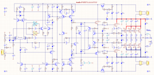
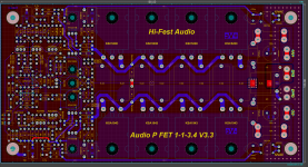
VFA P FET 1-1-3.4 V3.3

Attachments

JBL 2268HPL vented alignments

I've decided to build a pair of subs for my son's studio, likely using a pair of 18" JBL 2268HPL drivers. The goal is low THD in vented or aperiodic enclosures, to determine the best design for crossover points higher than most typical larger subs can pull off for their size.

At first we looked at dual 12s, but none of the decent reasonably priced 12s were capable of the low distortion figures the JBLs could do from way down low to way past 100hz. The SB34NRXL is the only 12 I've used with distortion numbers closer to the JBL ($400), but one of them is close to the cost of the JBL ($340). That means closer to $700 using 2 of the SBs, for the same cone surface area as the JBL. The SBs have the xmax advantage over the JBL 2268s, but that isn't relevant at higher frequencies closer to the LP cutoff.

I've heard the JBLs in various configurations and enclosures. They are likely the best 18s available under $500 for vented enclosures and open baffle based on my listening experiences. Because of this, my son has gotten ahold of a pair of the JBLs and wanted to build a pair of vented subs, but he's also open to aperiodic enclosures if they can go down into the mid 30s using little to none shelf correction.

We'll be running these off of 1000W Icepower plate amps with very light EQ, one driver per enclosure, per side. They'll mainly be used for mixing electronic pop, jazz and acoustic music. He plays drums and is very picky about low end. The bass has to be accurate and have exceptional dynamic capabilities.

I preferred the 2268s because they have an excellent reputation and sound great in the right enclosure at just about any level. This is another trait not typical with large pro audio drivers. We looked at 18 sound, B&C and Eminence, but the JBL always won due to price vs performance.

The enclosures were going to be 6 - 7 cu ft based on the preliminary specs I have on the 2268s. I'd like to hear about some of the designs others have done using JBL2268s.

Capacitor Recommendation For Recapping Cheap Bookshelf Speakers

Hello everyone,

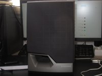
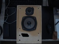
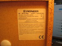
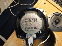
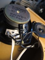
I have a pair of older Pioneer bookshelf speakers. They were probably never that great sounding, but I think they sound a little dull at the moment. They do not have a crossover, just a single electrolytic in series in between the driver and the tweeter. Can you please recommend a capacitor that is at max 10$ for one, that would bring a new life to them? I have heard a lot of praise for the film capacitors, would they be a good choice? Should the value remain the same (2.7uF)?

Thank you

Attachments

  • IMG_0937.JPG
    IMG_0937.JPG
    310.1 KB · Views: 85
  • IMG_0931.JPG
    IMG_0931.JPG
    331.2 KB · Views: 84
  • IMG_0935.JPG
    IMG_0935.JPG
    523 KB · Views: 77
  • IMG_0933.JPG
    IMG_0933.JPG
    483.4 KB · Views: 88
  • IMG_0934.JPG
    IMG_0934.JPG
    312.4 KB · Views: 90

For Sale Denon DL-103SL

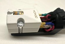
I purchased this and then was gifted a Denon DL-103FL

DENON DL-103SL Special Ceramic Moving Coil Turntable AT-MS11 Headshell $375 firm

This is a special cartridge. It was produced in 1989 with a white ceramic body for a more rigid body and faster response. It takes the already great sound of the legendary DL-103SL and takes it to the extreme. It also uses a 99.9999% high purity copper wire to reduce distortion.


s-l1600-9.jpg
Thanks for looking.

DIY-ish replacement for my Z-5500 Desktop system?

Hi all, sorry if this is a little redundant...
I've had a Logitech Z-5500 for like 15 years now on my various Desktop PCs. I've been super happy with it overall, but we've had a wild ride together. Several years ago, I replaced the main L/R speakers with 2 small bookshelf-size that I built with help from the kind folks here, using 3" MarkAudio drivers. They sound great. The rest of the system is stock.
Recently, I've started hearing some pops and crackles (almost a sizzling static) from all speakers when there's no other output. I'm afraid the amp, or some other internal component, is finally about to let out the magic smoke.
I would like to begin investigating options for replacement. My current PC (just built), has a Creative Sound Blaster AE-5 Plus sound card, so I'm working with 3x analog outputs that need to be accepted by whatever sound system I buy/build. I'd like to use my current main speakers, and I have 2 Definitive Tech surrounds that might make good rear or center speaker(s). Beyond that, I'm looking to buy/build whatever I need. I'm not interested in going the full AVR route. I've tried that once before, and not only do I not really have the room for it, I never got the inputs and outputs to work correctly with Windows. Also, I've heard about routing sound through HDMI via my video card, but that doesn't appeal either, since it involves a 'phantom monitor', which invokes all sorts of additional issues.
I thought about something like the Aiyima A09, but the one actual review I found of it wasn't encouraging.
As for the Sub, I would probably go with a Polk PSW10, unless you folks have a better suggestion in the same general price range. I've installed 2 of those in homes for friends, and they are solid units with good sound for the price, in my 'very much not a professional' opinion.

Bottom line: I'm looking for something that will sound as good or better than the Z-5500, doesn't take a degree in electrical engineering to set up, and won't totally break the bank. I'm not 100% fixated on 5.1, either. If there's such as thing as 3.1 (L/R/C/Sub), I'd consider that as well, if it sounds good enough. My rears aren't really mounted properly anyway. 😉

Any suggestions greatly appreciated!
I actually asked this question a couple years ago, and got no response. I'm hoping this time will be better. 🙂

UPV 50Hz on Output

Hi,

We just got a UPV back from an extensive service @ R+S. As it's discontinued and we are concerned about how long R+S will support it for, we decided to go for the full repair option, inc. 1 year guarantee (big hole in wallet).

The machine works like a charm and has the latest firmware (good). However, when either of the oscillator options are fed to the analyser (standard oscillator, B1 or B3) there is a 50Hz spike on the FFT (it goes from below -150dBV to around -120dBV). I shorted the I/P and flipped between analogue IN / gen 1 / gen 2 - and you can see the 50Hz is not there with shorted I/P and only present when loopback (or XLR leads from I/O) are used. Our other UPVs offer -113 THD+N with 2VRMS, but the serviced one only has -111 THD+N. If I feed it from another oscillator, it's cool, so the issue is isolated to the UPV output section.

My feeling is that a shield isn't grounded or a screw has been left out - that kind of thing. I am loathe to open the thing as it has a 1-yr guarantee. I am wondering if R+S will give us special dispensation to open it, assuming that there is an obvious instruction to fix it (hence my post here, to ask if anyone has taken one apart and can think of an obvious culprit?). It would be a bummer if we have to send it back to Germany just because someone left out an insulating washer...

They swapped the entire analogue board during the repair - repair report here:
12-months warranty on the entire product
  • Replacement of the Display Converter.
  • Replacement of the Analog Audio Board.
  • Replacement of the hard disk.
  • New installation of the image and the current firmware version 4.0.5.190.

The irony is that one of our UPVs was constructed out of a pair of totally broken UPVs (by us) that we bought for parts - and it has no 50Hz to worry about! We had front panel and keypad changed on the problem one, so it looks and feels like new....aarghh...

Any tips appreciated!

AD797 Clone people! Who can make a better one.

hi

Everything tells me, that AD797 is not only a very good operational amplifier
The topology used has got to be something extremely good!

Using only the simplified schematic from Analog Devices datasheet
I get some extraordinary simulation results.
(And I am used to see a few good figures, from my own circuits. Using same transistors.)

===============================

A few details from me, for those who want to try to make a better AD797 Clone.
... but I am not sure anyone could do this better than myself
... maybe get some similar results, but not better, I doubt.

My circuit is in attachment and follows the AD797 schematic
- what I know from reading This Datasheet Very Closely

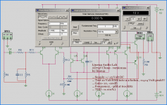
Lineup Audio Lab
AD797 Clone - version 2a
by lineup

... Supply +/- 15 Volt DC
... Test 10 Volt RMS into 2.2 kohm, = 14.14 Volt peak!!!
... Gain= x10, +20dB
... Frequency, -3dB at 600kHz
... THD <0.001%, my MultiSim does not show anything = 0.000%, see picture

Some more details:
All transistors BC550C and BC560C.
Total Supply Current 8.0 mA
Output stage, like the original biased only 0.5 mA ( 492uA more precise .... )

Good Luck Fellowes!
You may need really it 😀

Regards
lineup

Attachments

  • ad797clone-2a_10vrms.png
    ad797clone-2a_10vrms.png
    20.8 KB · Views: 5,236
  • Like
Reactions: ginetto61

Sound Stream Reference Ref5.1000 on protect mode

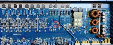
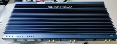
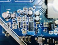
I am working with a Sound Stream 5 channel (Ref5.1000)m for 2 days now.It is a class AB amp. It is on protect mode, I had replaced a shorted transistor (TIP41C), a burned capacitor (10uf/25v) and burned resitor(1,2K) as shown in the picture wiht red circled, other than that i checked all the components but it seems all parts are good as far as I'm concern. What I found out was, there is no rail voltage because the TL494 PWM drive is not giving pulse signal to the FETs gates. The TL494 seems good I believed because I can see a saw tooth wave in the pin 5 and 5 volts reference voltage on Pin 14. Pin 12 Vcc is 12 volts to the ground. So i believed the TL494 is just shutting down the pulse signal output. As measured, I am getting unequal voltages on the non inverting and inverting inputs Pin 16 and 15(error amp) . Am I missing something? I did not try to replace the TL494 yet. Can anybody shed me some light on these amp. Is The TL494 deffective?

Attachments

  • SOunStream Ref5a.jpg
    SOunStream Ref5a.jpg
    204.7 KB · Views: 68
  • SoundStresam Ref5.jpg
    SoundStresam Ref5.jpg
    113.7 KB · Views: 60
  • SoundStream Ref5b.jpg
    SoundStream Ref5b.jpg
    245.6 KB · Views: 55

What kind of filter is this???

Im trying to figure out what kind of circuit can affect to q of a subwoofer system as described in the paper attached
1723613873088.jpeg

310Vanfig04.jpg


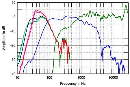
Fig.4 Vandersteen Model Seven, acoustic crossover on upper-midrange axis at 50", corrected for microphone response, with nearfield responses of upper-midrange unit (green) and lower-midrange unit (blue), both plotted below 350Hz and taken with high-pass filter in-circuit. Nearfield response of powered woofer shown with Contour set to: "1" (green), "4" (cyan), "7" (black), "9" (magenta), "10" (red).

To the left of fig.4 are shown the powered woofer's output, with its Contour control set to "1" (green trace), "4" (cyan), "7" (black), "9" (magenta), and "10" (red). (The 11 bandpass equalizer pots were set to their central, flat positions for these measurements.) The Contour control adjusts not only the amount of midbass boost but the low-frequency cutoff. Peculiarly, the biggest response changes occur when the control is set between "7" and "10"; a light hand on this control will be necessary. I set the woofer-level control to give an apparent crossover of 90Hz, but it should be noted that there is plenty of woofer gain still available. Again, a light hand on this control will be necessary to get the best match of speaker and room.
lowfreq contour (1).jpg

Attachments

Hello, another one joining from Finland.

Now that I'm finally retired from my day job, I have more time for these more interesting projects.

I've already repaired some turntables and recently acquired some cassette decks to work on.

I have to say that the restoration of the turntables was a "piece of cake" compared to these old cassette decks.

I am also interested in modifying loudspeaker crossovers to better suit my small listening room.

So there has been lot of interesting reading for me here at DIYaudio.

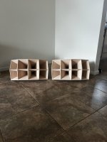
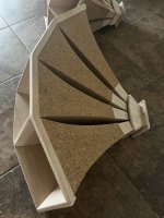
For Sale Markus Klug 805b Horns

Markus Klug 805b Horns
Brand new
Recommended crossover is 500hz and above (cutoff frequency 300hz)
For 1.4in CDs (3 or 4bolt)
Horns are natural with cork surrounds.
25in w x 13in h x 16in d
Asking $1500 free shipping CONUS

Attachments

  • IMG_1102.jpeg
    IMG_1102.jpeg
    418.9 KB · Views: 204
  • IMG_1105.jpeg
    IMG_1105.jpeg
    436.6 KB · Views: 195
  • IMG_1103.jpeg
    IMG_1103.jpeg
    511.3 KB · Views: 196
  • Like
Reactions: OtisCampbell

HELP: Acoustat Spectra 11 - volume issue?

Acoustat Answer Man - just joined this board to ask you a question. I have a pair of Spectra 11's powered by a B&K AVR-307. Sound great, like a hot knife cutting through butter.

My issue is that one speaker is definitely louder than the other. I have tried swapping channels and amps, but the issue is the same. Feels like something is missing in the sound. Is what I am describing a familiar issue? I read this thread here and it sounded similar:
https://www.diyaudio.com/community/...rostat-damp-and-subwoofer-replacement.334555/

A local speaker repair guru says they can take a look, but are less familiar with electrostatics. Is there a place in the circuity you might recommend them looking? I have another pro-audio guy coming to take a look. Trying to get these fixed in Denver, CO.

SS 1" Textreme Low Profile

Hey everyone, surprised others haven't noticed this incoming model from ScanSpeak. Textreme 1" dome tweeter. Aside from the coolness factor of Textreme (at least for the last year) what really is cool about this particular model is the low end extension and very flat FR for a low profile design. Even among SS tweets, their low profile (small face plate) models tend to suffer considerably compared to the full sized versions of the same line. Honestly wish I had this before my center channel build, I could have probably shaved an inch and a half off the height of the front baffle. 🙂

1723511292266.png


For a small baffle tweet these are some excellent results:
1723511691475.png
  • Like
Reactions: Arthur Jackson

Diy PFM flea not working properly

I have maranta cd63 which I modified 10 years ago with Ray’s version of the PFM flea to power a tent clock. After taking the unit out of storage, I’m getting a strange signal at the output of the clock and suspect this is the cause of the cd mechanism acting weird (speeding up like mad, with or without a cd in it). Where to start debugging?

(Can’t find a scope photo at the moment, imagine a sinusoid with sharp points)

whatelse will blow along with output transistors

Hi,

whatelse will normally go when the output transistors of an amp blow?

Might seem like a silly question as there are bound to be lots of possibilities but i was thinking that through your experience there is a likelyhood of other components that either made the transistor blow or will have blown along with the transistor.

I have come across a few amps recently that have all got shorted output transistors on one channel and when replaced they still wont work, only the one original unblown channel works.

Suppose what i'm looking for here is a - "when the output transistor(s) blow, always check/replace ..." sort of answer.

Please help!

Welcome the GSF Collective

Hello everyone
My name is Fabrice, i am running the "sound department" (if you can call it that) for a small party collective in southwest germany.
We are constantly looking for ways to make our horn system sound better.
We are currently using Martin Audio WSX, MKH 130 Kickfills and Limmer 308 Horntops.
In the winter i refreshed some old EV HP6040 Horns with some B&C DCX 462 drivers which are supposed to send the limmers into retirement.
I'm hoping to find a good solution for a new midbass horn in this forum that can do the same for the mkh's
Greetings
Breece

Short & Sweet - Greetings from Poland!

Greetings,

My name is Cyprian Wozniak and as stated in the title, I'm writing this introduction from my house in Poland (the country in Central-Eastern Europe, though I kinda wish I meant the town in Maine, US). My background is in electronics engineering, a field which I'm very fortunate to have been able to work in full-time for almost a decade.

I would not call myself an audiophile, but I do consider myself an enthusiast of all things audio - particularly the DIY kind, which has absorbed a substantial portion of my free time over the last couple of years.

Some of my completed projects so far include:
-About a dozen different 2-way bookshelf speaker designs (some passive, some active, sealed, ported, you name it)
-A few subwoofer boxes
-An experimental TQWT design using 8" Monacor SPM-200X/4 full range drivers (cheap, but with very surprising performance when given the right amount of care)
-Two power amplifier circuits utilizing TI LM3886 (Inspired by Tom Christiansens stunning LM3886DR)
Many other projects/experiments are in the works, some of which I hope to share with everyone soon!

Since day one of starting my journey with DIY audio, this forum has been an invaluable source of insight into speaker and amplifier design. I cannot express just how thankful I am to finally be able to become an active member of the forum 🙂

Thanks for reading my not-so-short and hopefully not too sweet introduction.

Wish all of you a lovely day!
  • Like
Reactions: abstract

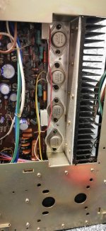
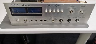
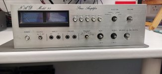
NAD Model 90 restoration

Picked this up for very little compaired to what it is worth, and its going to need a little bit of work, but a worthwhile restoration.Not many of these around these days.
Its going to need a full strip down.
Ive got a nice bright lamp, so i guess at least one of the outputs are shot-i have some MJ15003's, they should be ok.

Attachments

  • IMG_20240630_084520.jpg
    IMG_20240630_084520.jpg
    484.2 KB · Views: 218
  • IMG_20240630_084412.jpg
    IMG_20240630_084412.jpg
    488.9 KB · Views: 189
  • IMG_20240630_084355.jpg
    IMG_20240630_084355.jpg
    237.3 KB · Views: 179
  • IMG_20240630_084405.jpg
    IMG_20240630_084405.jpg
    336.5 KB · Views: 194

Introduction

Hello,
I’ve been an audio enthusiast most of my life. In the 1970s my friends and I had a lot of fun comparing and contrasting tube and transistor based equipment. We were fortunate to have access to equipment that sounded very good but did not cost too much. I have invested a lot of time and money since then (rare vacuum tubes, newer and vintage turntables, various DACs, music servers, amplifiers, speakers, etc). Some of it is stock, some of it is modified. It’s a wonderful feeling when it all comes together to make beautiful music, music that enriches and brings me joy.

Hello from another addict!

Hi All. Hello from the UK!
I'm a self confessed addict for lame hi-fi ducks.... I've tried to give it up, to the point of assembling my "final" system (Yamaha A-S2100, Marantz SA-KI Pearl, Garrard 401/SME 3009 and TDL Monitors), but I just can't resist the urge! Sold off tons of stuff and still have lots to go, then I come across a Musical Fidelity Tri-Vista 300!
Currently looking at getting this beast up and running (when I can lift it off the floor!)
Hopefully I'll find some like-minds here!

Help! Speakers are popping with iPhone/BT

Hello everybody! I hope someone can help. I'm new to the forum.

I'm running a basic set up, Denon AV 3803 receiver with a Logitech BT adapter, playing music through my iPhone.

Everything works fine, except when I use voice text there is a loud pop from the speakers. There is also a pop a few seconds after I stop playing the music.

I ran this same set up at my old house for years, and never had this issue. Now I'm in a new place and having new issues that I can't figure out.

Any advice would be most appreciated. Thanks!

Jim

My web site is back up. OUCH!

The gray-bearded electron wrangler prepares a sacrifice of old electronics gear and mutters:

;-} ;-} ;-} Magica parandi Web Hostiam et fortuna exemplar vetus lexici imaginum in computatro meo restituendi, praecipio tibi ut musingas illius veteris dudi insanis, quae VoltSecond, resurrecturus sit. ;-} ;-} ;-}

He shouts "OUCH" as the ritual text becomes case sensitive to his existing links and when finally resolved, a click me button is seen through the smoke and ashes!

https://www.voltsecond.com/

-Volt
Play Safe and Play Longer.
When in doubt, click the OUCH.

Attachments

  • DIY_Tombstone3A.png
    DIY_Tombstone3A.png
    7.2 KB · Views: 117
  • basic_plot_2.png
    basic_plot_2.png
    28.5 KB · Views: 112
  • ouchINDEX.gif
    ouchINDEX.gif
    5.4 KB · Views: 112

William Cowan Horn Sub Jr as midbass horn?

I’m looking to set up a home theatre and home party system. I Already have a swarm of 12” servo subs and looking to cover the 70-80hz to 300hz range with a horn loaded midbass.

I’ve been admiring the William Cowan Horn Sub Jr which is designed as a corner loaded sub but it occurred to me that this would make a nice free standing stereo midbass horn due to the clean wide bandwidth.

http://www.cowanaudio.com/

1723154691579.gif


I Have not plugged the numbers into horn resp yet but I imagine a narrower single 10” or 12” version with a midrange horn and high frequency horn on top would make for a nice PA style speaker similar to the funktion one Res units.

I am a big fan of the FLH sound for midbass for electronic music, and I’m putting this idea out there for critique.

I prefer FLH over tapped horn as I think it fits better with the design I have in mind with respect to bandwidth.

Looking forward to some feedback, cheers

Exploring High-End Component Upgrades for DIY Active Speakers with DSP

Disclaimer. The following was written by ChatGPT. I did it because my written English sucks

Hello fellow DIY speaker enthusiasts,

I've noticed a growing trend in our community where many of us are building active speakers with DSP using miniDSP and low-cost Class D amplifiers. This setup is undeniably cost-effective and provides a great entry point for anyone looking to dip their toes into the world of active speaker building.

However, it got me thinking: what would happen if we took our builds to the next level with higher-end components? Specifically, I'm curious about the potential sound quality improvements when using a good DAC, high-quality cables, and Class A or A/B amplifiers instead of the typical Class D amps.

The Current Standard: MiniDSP and Class D Amplifiers

For those who might not be familiar, miniDSP is a popular choice because it's affordable, versatile, and relatively easy to use. It allows us to implement sophisticated digital signal processing (DSP) in our speaker systems, fine-tuning the crossover points, EQ, and time alignment to our liking. Coupled with Class D amplifiers, which are efficient and budget-friendly, this setup offers a compelling balance of performance and cost.

Considering High-End Upgrades

1. Digital-to-Analog Converter (DAC):
- Why Upgrade? A high-quality DAC can provide a cleaner, more detailed signal, reducing noise and distortion that might be present in more budget-oriented options.
- Potential Impact:** Improved clarity, better separation of instruments, and a more precise soundstage.

2. Amplification: Class A or A/B Amplifiers:
- Why Upgrade? Class A and A/B amplifiers are renowned for their superior sound quality, particularly in terms of warmth, richness, and dynamic range. They tend to offer lower distortion and better linearity compared to Class D amps.
- Potential Impact: A more natural and engaging listening experience, with enhanced detail and depth in the music.

3. Cabling:
- Why Upgrade? While the debate on the impact of cables is ongoing, higher-quality cables can offer better shielding and lower resistance, potentially reducing signal loss and interference.
- Potential Impact: Subtle improvements in sound purity and consistency, although this might be less noticeable compared to DAC and amplification upgrades.

Hypothesized Benefits

By integrating a high-end DAC and Class A or A/B amplifiers into our active speaker setups, we might experience several notable improvements:
  • Enhanced Resolution: More detailed and accurate sound reproduction.
  • Improved Dynamics: Better handling of the dynamic range in music, leading to more impactful crescendos and delicate passages.
  • Greater Musicality: A richer, more engaging listening experience that captures the emotional essence of the music.

Real-World Testing and Comparisons

Of course, these are hypothetical benefits, and the best way to understand the impact of these upgrades is through real-world testing. I'm eager to hear from anyone who has experimented with high-end components in their active speaker builds. Have you noticed significant improvements? What components did you find to offer the best return on investment?

Conclusion

While miniDSP and Class D amplifiers offer a fantastic starting point, exploring higher-end components like a good DAC, high-quality cables, and Class A or A/B amplifiers could elevate our DIY speaker projects to new heights. I'm excited to hear your thoughts, experiences, and any recommendations you might have for those considering these upgrades.

Happy building and listening!

Best regards,
Martin

ES9038/9039 & AK4493 boards and ICs from China and possible fakes?

I have been looking at building my own 8x I2S DAC or modding Chinese boards for this purpose.

Current pricing on mouser.de (+ 19% tax) and on Aliexpress (EU tax included) 1 IC and one board
ES9038Q2M 1+ € 17.86 3000+ 11.01 1 pc. $3.23 > $24
ES9039Q2M 1+ € 15.81 100+ 11.86 1 pc. $ 8.16 > $32 (> $55 only a few days ago)
AK4493SEQ 1+ € 8.69 2500+ 4.74 1 pc. $ 7.52 > $46

So the AK is the cheapest at at a reputable distributor. ICs from Ali are only a tad cheaper, which is reasonable considering dealers were buying them by the thousands. Boards are strangely expensive, starting at $46, but are typically more like $ 55-60.

The 9038 can be had for about a third of the highest bracket at Mouser, and boards have been cheap for a while starting at $24. Does ESS sell the chips at a tremendous discount in China or could these be fakes?

Interestingly, the 9039 is cheaper than its predecessor at Mouser in spite of being fairly new. Again, IC prices at Ali are lower than the highest bracket at Mouser. There seems to be only a single board design available on ebay and Ali, which was north of $ 50 only five days ago but now has dropped to the low 30s at several dealers. Strangely, this board uses only a single DIP8 op amp by JRC (presumably a dual, so one amp for each channel) whereas the datasheet recommends 2 or 3 amps per channel. Could these be rebadged voltage out DACs?

Dynaudio 17W75 XL 08 vs. 06: What's the Real Difference?

귀하의 메시지 번역은 다음과 같습니다.

저는 현재 Dynaudio 17W75 8옴 우퍼를 사용하고 있으며, 성능에 상당히 만족하고 있습니다. 그런데 최근 17W75 XL 08에 관심이 생겨서 조사해 보고 있습니다. 검색을 하던 중 17W75 XL 06을 발견했는데, 역시 8옴 모델입니다. 17W75 XL 08도 8옴인 걸 알았지만, 두 모델의 차이점이 궁금합니다. 모델 스티커도 다른 듯합니다. 08과 06의 차이가 크지 않다면 구매를 고려하고 있습니다.

trying to repair car underseat sub JBL BassPro SL / Infinity Basslink SM

Dear all,

My sub (JBL basspro SL) stopped working a while ago and I felt like trying to see if I can repair it myself as a challenge- I don't have much experience in repairing such boards though I meddled with designing some simple medical amplifiers (studied EE about 30 years ago)

I opened the sub and removed its board and immediately saw 2 burned wires on the ferrite beads L03 and L04 in the power board (see 2 yellow markings on left of image). the schematic is attached (infinity_basslink_sm.pdf - this is the schematic for basslink sm which is what is printed on the circuit board!) and these beads appear on the 10th page (titled "CIRCUIT DIAGRAM - POWER BOARD") on the bottom left. they sit between the sinks of 2 mosfets and ground.

I tried yesterday to solder these 2 melted wires hopeful that they may have been fried during some maintenance or sloppy disconnection in the past- i reconnected the sub to the car and it worked great for a few hours!! before i left the car i tried calibrating some of the input levels and phases etc until the levels sounded well and left the car. When I started the car later that daythe sub didn't work and taking it apart again saw that the 2 wires and my soldering has melted again.

I tried checking continuity in the 2 mosfets with my Fluke in diode mode IN CIRCUIT and it seemed that the volatge differences between S/D/G are as expected (0.5 V/ no short?)

PS the transistor Q07 and an adjacent resistor seem to have hot marks on the yellow foam- see picture

Any ideas on what happened or how to proceed will be most welcome!!!!

Thanks dearly in advance,

Michael

Attachments

  • circuit_board_L03_L04_marked_afterfix_fry2.jpg
    circuit_board_L03_L04_marked_afterfix_fry2.jpg
    326.6 KB · Views: 246
  • L03_L04_detail_before_fix.jpg
    L03_L04_detail_before_fix.jpg
    229.4 KB · Views: 139
  • Q07_seems_hot.jpg
    Q07_seems_hot.jpg
    287.5 KB · Views: 145
  • BASSPROSL_QSG_EN.pdf
    BASSPROSL_QSG_EN.pdf
    9.4 MB · Views: 158
  • infinity_basslink_sm.pdf
    infinity_basslink_sm.pdf
    1.9 MB · Views: 133

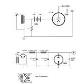
71A preamp design

Hi, hoping to get your thoughts on a simple pre-amp design using the 317A tube. I don't need much gain. Looking to add some tube sonic flavor. Source is a streamer (600ohm output, 2Vrms). Amp is solid state with 10K input impedance.

A few specific questions on the schematic:

1. Is the 1 uF cap sufficient? I don't need much below 30hz.
2. Is the OD3 tube regulator necessary? Will it improve sound?
3. I have read quite a bit on AC vs DC filaments. I would like to try AC from a simplicity perspective. Any issues with this?
4. The autoformer is at the input, instead of output. Sound ok?

Looking forward to your input/guidance.

Attachments

  • gi.png
    gi.png
    21.4 KB · Views: 304

6W6 triode operating point

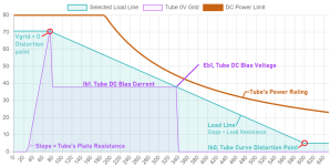
The 6W6 has been brought up many times in various threads, lots of positive comments about triode operation. Tubelab has had some comments about runaway in triode operation when running closer to the normal sweep duty ratings. (300V plate, but only 150V screen rating, so triode operation easily exceeds the stated screen rating.)

The one data sheet I could find floating around from RCA gives a triode operating point at 225V, -30V, 22mA. I'm considering for duty as a headphone output stage or perhaps a push-pull 300B driver stage, running around 190V, -23.5V, 25mA. This gives Pa of 4.67 watts, and spice models suggest screen dissipation around 320mW. Obviously this still exceeds the 150V screen rating, but I doubt everybody using 6W6's in triode are running that low. Those screen dropping/shifting circuits could help, but I'd be nervous about how low the screen voltage would get when driving 300B grids, for example.

If anyone has been running some in triode mode and gotten a good long lifetime out of them, what operating point are you actually running at? I haven't seen many definitive comments about op point. Price does seem to be creeping up, and though I have a couple nice pairs already I'd rather not abuse them unnecessarily.

Marantz Superscope C-205 motor

Hello everybody.

After successfully restoring a Superscope CD-330 a few months ago, I've bought another Marantz from the same series, apparently in very good conditions, this time a C-205. The eBay seller said "probably needing new belts". When I received it I made a quick test test, I could hear/feel the motor running but nothing moved, and when I opened it I found the two main belts, the ones on the underside of the mechanics, reduced to a black goo. I ordered a replacement set and while waiting for the new belts I completely cleaned the recorder on the inside and on the outside.

The Superscope C-205 is a mono recorder with adjustable playback speed based on the same chassis of CD-330 and CD-320. Being mono, the inside is a little less crowded and messy than the CD-330, but they look very similar. I cleaned all the tape transport parts and all the selectors and potentiometers.

I received the new belts today. After changing them I tested the recorder but the motor wasn't spinning anymore, so I unscrewed the mechanics and inspected it once again. Everything seemed fine, no missing parts or orphaned wires, so I pressed play once again and the motor started to spin again. It works, but I noticed some hard wow and flutter and that the motor isn't running at the correct speed: I had to move the speed regulation potentiometer to about +15% to actually have the tape playing at normal speed.

I noticed some problems with the rewind too, as when I engage it I can hear the motor spinning but the tape isn't moving, and goes to auto stop within few seconds, but I will investigate that later.

With more tests, I discovered that the motor not always works when requested, but it does if I gently start the spinning of the motor pulley with my hand.
So my first guess is: the motor is defective and needs replacement. Do you agree? Or should I look for other problems?

The problem is: what motor is that? The label on that gives only the Marantz product part code (MM10600520), it says it's a 6V Matsushita motor produced in 1980 but nothing more than that. I made a quick web search but I couldn't find more detailed info. As far as I can see, only two wires go inside the motor (well, actually it's just a single shielded wire with + on the inner conductor and - on the shield mesh), and looks very similar the motor used on CD-330, but the service manual say it's a 2200 rpm motor, while the CD-330 one is a 2400 rpm one. I can find a replacement for the 2400 rpm motor but I can't find any for this one.

Do you have any suggestion?

Thank you in advance,
Lorenzo

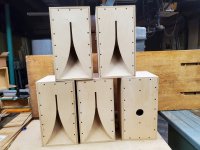
For Sale Karlsonator 53 enclosures

For Sale
Karlsonator 53 enclosure in baltic birch.
17"h x 9-3/8"w x 9-7/8"d
Removable rear panel
Removable baffle so you can easily fit the drivers.
Aperture, driver baffle, and rear panel fasteners #2 square drive.
2 inch diameter hole in rear panel for terminal cup.
About 14 pounds weight.

Baffle sized for PA130 or a pair of Faital 3FE25 or a pair of TC9FD drivers. You cut the appropriate sized cutout for your driver of choice.

I have 5 of these.

$100 each plus shipping FOB zip 98258

Attachments

  • Karlsonator 5.jpg
    Karlsonator 5.jpg
    416 KB · Views: 1,617
  • Like
Reactions: taloyd

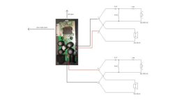
How to correctly AC ground the negative input of a RCA input?

Hello everyone,

I would like to ask you to point me in the correct direction. I am building a class D amplifier utilizing the TPA3128D2. In the datasheet I have read that "To use the TPA31xxD2 with a single-ended source, ac ground the negative input through a capacitor equal in value to the input capacitor on positive and apply the audio source to either input.".

Which one of these is correct?
IMG_0940.JPG


Thank you.

A DIY Beginner's Journey

I began my DIY adventure about 1 year ago and thought it might be helpful to put together some suggestions for tools and other chachka to assist others getting started on their journey. It is worth mentioning that I have managed to spend $20 +/- on many items, wire, LEDs, screws, standoffs, crimp spades and the list goes on, so if you want to get into this you should anticipate additional expenses and time to get the stuff. I ordered some bevel head screws yesterday from Amazon, and they are waiting for me at home, Amazon Rocks!

Something that occurred to me last night, a very worthwhile purchase, perhaps a necessity, a Fire Extinguisher!!!!!

Just posted this further in, but it is worth repeating, It is a wise person who knows when to take a break! Along with this spending a minute or two to double check and then check it again can save hours of frustration!

The first thing is to have an organized work space and extra storage for various tools and supplies. Storage for supplies turned out to be a big one for me as I accumulated a lot in a relatively short time. If you are going to get serious about DIY there are many things that will make your projects look better and likely perform better. I generally find that it is better to pay a bit more to acquire quality tools that will function as expected and last. Having a notebook for projects can prove invaluable, having a place to notate, refer, and document can be a real time saver, and if for some reason you have to put your project on hold 😱 it's much easier to pick up from where you left off.

Tools:
1. A quality soldering station, my first one was a ToautoDS90 from Amazon, notice that the wand is held to the body by a plastic nut. Plastic nut, high heat 🤔, yes it comes apart frequently. I ended up replacing it with a Hakko FX888-D, much better!!

2. This is a good place to mention solder and Flux. Initially I started off with various Silver solders, Audioquest, Wonder Solder but switched over to Kester 24-6337-8800 50 . I have no way of telling if there are sonic advantages to Silver solder, but the Kester melts at a lower temp, flows nicely and is much easier when you need to de-solder. Speaking of which I like Vampire Tools Solder Sucker. While I started soldering without Flux I found that a judicious amount of Flux is quite helpful, both for soldering and de-soldering, this, MG 8341-10ML Flux Paste, 10 milliliters Pneumatic Dispenser, works very nicely, small amounts go a long way. To help clean the board I am using Chemtronics ES1696 Flux Remover 12 oz.. Another thing worth mentioning is temperature used for soldering, I would invite anyone w/ more experience to chime in, but I typically solder at 700F, although there are some applications that require more, ie. soldering speaker wire to binding posts, according to @ItsAllInMyHead, IIRC, 800F for this would be better. That being said, I was taught by the folks at Mark Levinson decades ago that the mechanical contact is most critical and solder basically seals the joint.

3. After additional reading/research it seems clear that crimping is preferable to solder, though if done correctly sealing the joint with solder can be beneficial. As in most things because a method is recommended and potentially superior it requires the correct tool to create good quality crimps. As mentioned in the Section, "Chachka AKA Stuff" there are various types of crimp connectors, insulated, non-insulated etc., and each type requires a different "jaw". Haisstronica 6PCS Crimping Tool Set, appears to be very nice, got 1 due tomorrow 😉. Regarding "sealing" a connection with solder, it is a :nownow: to tin wire prior to crimping as this not only mitigates the advantages of "fusing" your connector and wire, it can cause the premature failure, and no one likes that! Soldering to seal the joint does require some expertise as you don't want to wick solder into the wire.

4. When soldering it is often helpful to have a third set of hands, and this is where "Helping Hands" come in handy. There are many to choose from, but I prefer relatively cheap ones of this type, for much of the work I prefer Magnetic Adjustable Circuit Board Hold.

5. THIS is potentially less known but incredibly useful, Lead Bender, these will help get consistent, properly spaced bends in the legs of resistors etc., which not only adds to the aesthetics but likely the overall performance.

Lead Benders.jpg


6. A "Shear Cutter" Diagonal snipper, Xcelite 170M, is what I have had for decades.
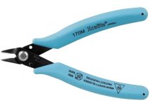
71TCVWqvtCL._SL1500_.jpg

7. Obviously an assortment of screwdrivers and various bits, iFixit, is an outstanding driver set w/ a very nice aluminium 😉, handle and a nice assortment of bits.
Mr Fixit Drivers.jpg


8. Preciva Ferrule Crimp Kit, something that I was unaware of until @ItsAllInMyHead, thanks, suggested it! This is inexpensive, good quality and makes connecting wires to euro blocks more secure. What more could you ask for? It was recently pointed out to me that the ferrules come in 2 different shapes, thanks @vanofmonks, square and hexagonal. Apparently the square ones are designed for the euro blocks on my Aleph Jzm, but the hexagonal when tightened down flattens out and works beautifully.
Preciva Crimping Tool.jpg


More to come.

Something that I should have mentioned earlier, keeping your solder tip clean, a moist sponge is handy, will yield better conductivity and make your tips last longer.

9. A magnifying/lamp is very handy, but to inspect work it's hard to beat a pic from your phone.

10. A heat gun, Seekone Mini Heat Gun is reasonably priced, works well and takes up minimal space. Shrink tubing of various sizes not only enhances the look but can prevent accidental shorts. You will have a few options for shrink tube, 2:1, 3:1, w/ adhesive and without. My favorite for most use is non-adhesive 3:1, it's a bit harder to find but is nice if the price is reasonable, otherwise 2:1 works fine.

11. Clearly multi-meters are a must, and it is definitely worth while having 2, 4 is even better. When biasing your amp you will find it much easier to use 2 meters/channel to adjust both bias and DC offset without having to go back and forth. I recommend either getting a meter that includes plunger mini-hooks and banana ends or purchasing something like Micsoa Multi-meter Test Lead Kit.

12. A variac or DBT, Dim Bulb Tester, is definitely a good idea if you build any kits and especially so as the $$$ and power go up. I have been resisting getting a variac and have some older incandescent bulbs, new ones are available as "Appliance" bulbs. There are some posts re. DBTs including 1 that I just built, including diagrams.

13. Wire strippers are a necessity, I use Klein 1009, a quality tool that will last a lifetime. Take note that it is etched with "Stranded" and "Solid" which are different notches for the same gauge of solid or stranded wire. For finer gauge I have an old Greenlee that strips as fine as 26 gauge, the current version, 1917SS, is a bit pricey but looks nice.

Many of the projects include pretty much everything that 1 needs to complete a build, but having chachka on hand can make a build easier and more professional looking. Some have already been mentioned in Tools, so I'll skip them with the exception of a second mention of the Ferrule Crimp Kit, I just like that word, Ferrule hehehe!

Chachka AKA Stuff:

1. An assortment of both insulated and "sleeved" spade connectors, see Tnisesm, is worth having. It has appropriately sized female spades for just about any situation that you will run into. As a generalization I like to use Spades/Ferrules in power supply sections of my build, I mentioned earlier that I had been taught that mechanical connection first and use solder to seal the joint, perhaps someone w/ more experience might chime in on this?
Something like Mentbery 160 piece male/female spades, is a nice kit.

2. Having an assortment of metric fasteners can come in handy. My collection of metric screws, bolts, washers, nuts etc. has grown a bit, and while they come in little organizers I just ordered some "Crafts" organizers in an attempt to consolidate.

3. It is highly likely that there will be times when you will need additional wiring, based on suggestions by other forum members as well as reviews on Amazon, :radar:, I purchased 16 and 18 gauge silicone insulated wire from BNTECHGO, also, Xinwang 22 Gauge Silicone Wire..

4. Having a Dymo Label Printer can come in handy, especially coupled w/ Heat Shrink Tube Labels.

After using Haisstronica crimper for a while, I am very happy with the quality and results. Love products that meet or exceed expectations, hence my 😍for this site!
Technics SE-9021 DC on speaker output

Hello everyone,
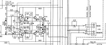
First post here, hopefully someone can help me out diagnosing this SE-9021. The problem I'm having is an intermittent thump and crackling from the right channel. The problem sometimes goes away for a few hours but always comes back. All caps have been replaced prior and after being unable to bias the DC offset correctly, I started meausuring DC voltages across the board. All seem to be well except for the base of TR118, after each DC spike on the speaker terminals, here the voltage drops to +- 0.5V and lower. I'm also getting spikes on testpoint 104 and 106, which seems logical giving the circumstances. The problem seems to happen most in low cut mode instead of DC (not even sure what this means). My best guess would be a bad coupling cap or a transistor going bad but because all the cap's have been replaced, probably the second? I'm pretty new to hifi repair so any tips and tricks are welcome!
Thanks for the help!
Jesse.

Attachments

  • Scherm­afbeelding 2024-08-07 om 15.22.04.png
    Scherm­afbeelding 2024-08-07 om 15.22.04.png
    116.3 KB · Views: 92

Graaf GM20 mods - help!

Evening all - I'm afraid I'm a newbie...

I have a pair of Graafs GM20's (schematic via link) but the constant tweeking of bias and offset is driving me mad!

https://cid-a332bc3aefc89f6b.skydrive.live.com/self.aspx/Public/GM20 schematic.pdf

Is there a way of adding an auto bias circuit?

Also, can anyone suggest any tweeks / improvements? I've scoured the net but nothing forthcoming.

Ahh, can I reduce the gain / adapt the present circuit to suit a higher input voltage without using a pot and thus destroying the dynamics? I'm using a Weiss Medea DAC with +27dBu via XLR's....

Thanks guys 🙂

Easy way to get audio from Windows into a separate Ubuntu PC running CamillaDSP

For years I have been using Foobar2000 on Windows 10/11 into Cantabile. This host several VSTs, to work as a 4 way crossover / DSP.
The audio then goes over USB into my 8 channel DAC, followed by nice hypex modules to drive my DIY speakers and 2 subs.
I love Foobar2000 and use Windows for my work, so I would like to have this stay my primary PC, and the way to play audio.

But I would like to offload this audo processing to a separate laptop running CamillaDSP on Ununtu or Debian. To try, for fun, to tincker.
No problem, I figured.

But then I got stuck: how do I get the audio from the windows PC into the CamillaDSP laptop?
The laptop does not have a digital audio input. Does anyone know of a software solution? Eg to run the audio over ethernet somehow.

Of course there is Dante. The AudioOverIP stuff seems much too complicated and expensive for my use case.
I also came across SonoBus, which is available for windows and Linux. It is open source, which I like, but is looks more geared towards multi-user cases and don't know if it will connect to CamillaDSP (I'm a complete Linux-noob).

But there must be a simple (and cheaper!) solution I'm overlooking?
Your ideas would be appreciated!

Btw: does Ubuntu natively support a USB XMOS UAC2 DAC? Or does it need drivers?

Virtual machine to play Tidal and audio files, Windows OS or ... ?

I am installing my home cloud and media server.
The system is based on an Intel i5-12400 CPU with 32GB of ram, and is running Proxmox as supervisor.
My goal is to install a virtual machine to which to passthrogh an entire USB channel for the SMSL M400 DAC, and play audio from TIDAL or from a music player.
Since TIDAL is moving all MQA to FLAC, I may don't need the Windows tidal app/player anymore.
In fact, I want to play hi-res FLAC files and DSD files as bitperfect as possible, and TIDAL gapless. What are your suggestion for the operating system and software to install?

Bose Companion 3 Series II hiss

Hello everyone,

Need some advice on a Bose companion 3. This weekend I've sort of finished a repair of a Bose companion 3 Series II (2.1 speaker) system. The set is from a friend of ours and hadn't been used for a while. It sat in the attic doing nothing but collecting moisture (and fungi 😏). So the thing was in a terrible state with lots of noise when switching on (if it even wanted to). So took it apart and started replacing all SMD electrolytic caps because some of them looked leaky. Found out that lots of them were actually leaking and / or in a bad shape anyway. Especially the 10uF ones were bad and needed to be replaced.

So after going through all of that it is now working again. But the amount of static / hiss this thing produces is beyond what I find acceptable. However, it might just be poor design. Since I've never had a BOSE on my bench, is it normal that this thing is so noisy? I wouldn't mind digging in a bit deeper but now feels like I'm chasing red herrings.

So far I did find the full service manuals, bulletins and schematics (although being the wrong revision of the board). It has a peculiar power supply and a tiny voltage regulator for all op-amps and bias voltages. My guess is that noise in the power supply would easily get into the amp and out the speakers (the hiss is present in all channels).

Transitional Miller Compensation (TMC) vs. Two Pole Compensation (TPC)

Once again, wanted to find these posts and threads by a title search rather than digging for them.
EDIT: This thread was intended to make it easier to find posts on the subject but I'm having to fix the links again.
This time I'm providing the post # so that if the links break again one can search by post #.
I searched on Megajocke's posts and found that his analysis is now on page 61, half of the last link to page 122,
so perhaps posts per page have doubled.

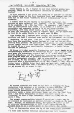
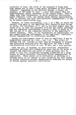
TMC is a derivative/improvement on Cherry's Miller inclusive compensation (or Miller output inclusive) that was first described and tested by Peter Baxandall and refined and promoted by Edmund Stuart on here. Baxandall did not publish his work, rather his wife, after his death, forwarded his notes on Douglas Self's book to him and they included the yet unnamed concept of TMC. Self has posted the TMC part of those notes here: EDIT site no longer works so I have attached the pages below to this post.
And they are published in full in Linear Audio's "Baxandall and Self on Audio Power". The book is a collection of previously published papers by Baxandall and Self with his notes to Self at the end. Cherry's Miller inclusive compensation was used in very early OP amps of the 1970s and it is reported to work less well in power amps where the output stage significantly slows down in saturation. Post by Edmund Stuart on Cherry's work, POST #854 for future reference: https://www.diyaudio.com/community/...er-amplifier-book.171159/page-43#post-2390542

TMC acts as Miller inclusive at audio frequencies but transitions to normal Miller compensation at HF where stability is important providing the best of both worlds.

Much of the detailed analysis and even the naming/promotion of TMC by Edmund Stuart happened on this forum and I wanted to use this thread to collect some of the better links.

Controversy started over TMC when some (michaelkiwanuka) claimed that TMC and TPC were essentially the same thing. I at first did not believe this, BUT some of our best people here jcx, megajocke and others backed up the claim. Megajocke's analysis here has convinced me with regard to small signal analysis but I believe that there are potential differences when the output stage saturates and the parameters change. Here is Megajocke's excellent analysis, POST #1220 for future reference: https://www.diyaudio.com/community/...er-amplifier-book.171159/page-61#post-2414320

Several argued that TMC was first order compensation as is normal Miller Comp but Megajocke pointed out that that was with regard to the global loop and that if one probes inside the local TMC loop there are other stability issues to consider. jcx argues that it is mostly not a first order system: EDIT POST #1100: https://www.diyaudio.com/community/...er-amplifier-book.171159/page-55#post-2406839

Another good post by megajocke with a response from Bob: POST #1239: https://www.diyaudio.com/community/...er-amplifier-book.171159/page-62#post-2415553

One of megajocke's simulations: POST #1163: https://www.diyaudio.com/community/...er-amplifier-book.171159/page-59#post-2411182
AND POST #1252: https://www.diyaudio.com/community/...er-amplifier-book.171159/page-63#post-2415855

Simulation from Bob showing that it is possible to choose compensation values in TPC to get the same distortion performance as TMC, he uses a simple Blameless topology for the example: POST #1184 WITH .asc FILES: https://www.diyaudio.com/community/...er-amplifier-book.171159/page-60#post-2413197

POST #1027: https://www.diyaudio.com/community/...er-amplifier-book.171159/page-52#post-2402170

Post by Bob of his MOSFET amp with the EC removed and TMC added, he mentions the excellent distortion results. On closer inspection this is actually a MIC/TMC hybrid, very interesting, also note the driven cascode: LINK FIXED, NOTE THAT IT IS POST #1602:
https://www.diyaudio.com/community/...er-amplifier-book.171159/page-81#post-2537043

Post by Bob with simulation of Bridged-T TMC POST #1339 for future reference:
https://www.diyaudio.com/community/...er-amplifier-book.171159/page-67#post-2421505

Wish I had time to read the entire thread and carefully link all of the best posts and simulations but there is just not enough time in the day - this is a start.

I'm inclined to use TMC, perhaps with gentle lead compensation in a new design but it is important to observe the changes in stability when the output saturates and with capacitive loads. I'd want to see if TPC is better stability wise when tuned for similar distortion. I was firmly in the TMC camp but megajocke's and jcx's posts have made it clear that they are similar but my opinion is perhaps not from a large signal perspective.

Attachments

  • Baxandall papers 30.jpg
    Baxandall papers 30.jpg
    522.3 KB · Views: 137
  • Baxandall papers 31.jpg
    Baxandall papers 31.jpg
    563.4 KB · Views: 157
  • Baxandall papers 32.jpg
    Baxandall papers 32.jpg
    443.8 KB · Views: 162
  • Baxandall papers 33.jpg
    Baxandall papers 33.jpg
    512.2 KB · Views: 167
  • Baxandall papers 34.jpg
    Baxandall papers 34.jpg
    471.6 KB · Views: 155
  • Baxandall papers 35.jpg
    Baxandall papers 35.jpg
    360.6 KB · Views: 158
  • Like
Reactions: hbtaudio

Jungson JA-88D crackling and static fixed!

No requests or debates, just wanted to share a success:

Over the last year, my Jungson integrated started creating some crackle and noise from the left channel.

Checking the output, measured a dc offset of >200mV, and fluctuating about 50% higher sometimes. It did settle a bit after warning up, but never completely went away.

Found this site with some info on mods and schematics:

JungSonJA88D-09

And located the trim pots top zero the positive and negative offset.

Now the amp is dead quiet! I think one of the protection circuits may have been fighting the output to try and reduce the offset.

Hopefully this may help someone in the future.

DIY vs Pro stock?

For extracting main and sub channels from stereo signal. Is it better to DIY long term stable results or live with the compromise of fewer options by buying a commercial unit from a pro brand?

Let's leave DSP out of this. There are times when one wants hands on knob per function and quick visual reference

What are the important bits? Online searches mostly show analog audio processors from the car scene. There is one generic design that seems to be offered under many brands. The link below shows one. This has variable knobs for frequency but slopes are missing as well as the very important subsonic with a variable knob. This exact design appears at different prices between the brands too. Like AU $100 for Boss and $200 for more well regarded brand

https://www.ebay.com.au/itm/1855986...2256156830&itmmeta=01J4X32P6Z0Z7HVMBBT1KC6DQ2

While this one from pro brand PRV has no slopes and uses limited selection of frequencies with the step slider. It has the important subsonic filter but still with the stepped slider

https://www.ebay.com.au/itm/1337731...9049227912&itmmeta=01J4VNT95QA9T91DVTXR2A47MR

And this pro mobile unit from DS18 has to be used on the subs and another on the mains and still doesnt have slopes selection

https://www.ebay.com.au/itm/1859863...0058991206&itmmeta=01J4X32P5ZMEK8FZCD8AT6DXC3

The generic design is only missing the subsonic filter and slopes. Can something like this be DIY'ed and exceed durability and signal performance? Is there a proven DIY design that can be built in a solid and mini console format with dedictated knobs per function and superior sound?

Fortè 1A problem - whistle

Hi,
I am an happy Fortè 1A owner from Italy 🇮🇹.

A little bit of my personal history: my dad owns a Threshold T50 for 30 years and I aways loved that kind sound, that warmness and that soundstage. I listened that amp since I was born with a pair of Strateg Cyan, an old school handcrafted bookshelf speakers with a 16cm Seas P17 woofer and a 25mm focal t121 tweeter, all in Mogano, assembled by interlocking so without using adhesives and without any sound-absorbing material inside and produced by a local brand - STRATEG by Lorenzo Corsi - that was active until some years ago - https://www.tnt-audio.com/tours/strateg.html). So after discovered that Nelson Pass was behind not only the Threshold but also the Fortè Audio, some year ago I found a used Fortè 1A that, if I understood well, is a project similar to the Threshold T50.

From that moment I’m in love with that amp and even if I try different speakers it’s always pure magic (now I use the Forte 1A with a pair of Martin Logan Motion 20i and I’m really really happy, that folded motion tweeter with this amp ... 😍).

But a month ago appeared a problem: a channel, the left one, started to emit a sound like a whistle, someday not so high, someday higher.

I tried to disconnect the input but the whistle remains.

I also tried to buy a filtered power socket but the whistle is always there.

At the end I tried to open the top cover to blow a little air but nothing changed.

I read here a post of some years ago that talks about the bias and to try to adjust it slowly but I’m a noob.

Someone have any idea about this problem? Who knows a trusted repair service here in Rome or in Italy?

If someone can give me some advice I can give it to a local repair that I know. My concern is about the possibility of changing some components that could modify the amazing sound of this amp.

Thanks in advance.

UNFIXABLE power supply!!?

Hi, i'm a hobbyst that remained stranded after my lab bench power supply died.


Here is what happened in details:

Power supply specifications:
220 - 240VAC input, 30V 10A MAX output.

Current and voltage can both be regulated from 0 to MAX. One day, i was using the power supply when it suddendly stopped working and its fuse was blown. (Fast 3.15A 250V).

So... Let's replace it and see if it works again. Plugged it in... Fuse blew again. So i opened the power supply to access the board, and found out that BOTH MOSFETs in the half bridge and the double diode were COMPLETELY shorted. Every pin to every pin.

So... Let's replace them, it will surely work again... And i replaced them with EVEN BETTER components (thats what i have for now). The mosfets were 500V 9A with 1+ ohm RDS(on).

I substituted them with 400V 24A 0.24 ohm RDS(on) mosfets. The double diode was 200v 20A and i substituted it with a whopping 60A 200V double diode (of course it is a shottky one).

This will also make the power supply slightly more efficent and heating will be reduced. New components and fuse set up.

Plugged it in, and it turned on! But... That was short lived. I tested it under load at 12V with a 12V 60W incandescent Light bulb. It worked. But after i rose the voltage a but more it broke again and the fuse blew.

Opened it up... EVERYTHING SHORTED AGAIN. Even the 60A double diode... Completely shorted. Frustrated, i changed the components again (same components as before) and then tested the power supply differently. I bypassed the fuse and i connected the power supply to a pure sine wave inverter with a soft start function and a series 100W incandescent light bulb to prevent catastrophic failure. The power supply turned on and i set the current to maximum and the voltage to 12V.

Then i started to short the output multiple times. Nothing bad happened. The voltage what set to 12V though. Then i set the voltage to 15V and after shorting / loading the output few times, it broke again and the light bulb went full brightness. This time thanks to the light bulb the two MOSFETs were saved, but one half of the double diode still shorted.

When the power supply was functional, i could short the output even with the voltage set to 30V and the current to maximum without any problems.

In 7 years NEVER a single problem. It always worked. So the question here is... WHERE LIES THE PROBLEM?

Does the main transformer have shorted turns? Some defective control IC? I tested all the rest of semiconductors in the board and they are not shorted / open circuit.

I would really appreciate it if you could help me resolve this problem. Without the power supply i cant do anything...

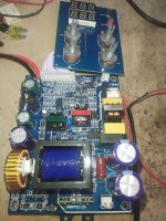
Here is a photo of the board in case you need it. I also measured the inductor and it seems fine (92uH).

The blue transformer is the main one, the green one is the gate driving transformer and the red one is used in a small secondary power supply to power the control electronics and display.

Attachments

  • 17227590519926929083145754462969.jpg
    17227590519926929083145754462969.jpg
    515.5 KB · Views: 141

F5 diyAudio Amp

-SOLD-

Thinning out the number of amps I have. I built each of the amps for sale for personal use and am selling for below cost of construction.

Basic details: Deluxe 4U chassis. Antek AN-6218 transformer, Toshiba JFETS. Takman metal film resistors, Mills power resistors, Vishay TX2575 signal path resistors, Mundorf PS capacitors, Cardas and Kimber wiring, EAR Isolation feet. Functions perfectly. Will be carefully packaged for shipping.

$600 incls. shipping within Continental US. Payment via Paypal.

Attachments

  • F5_0600.jpeg
    F5_0600.jpeg
    327.5 KB · Views: 355
  • F5_0599.jpeg
    F5_0599.jpeg
    465.9 KB · Views: 315
  • F5_0598.jpeg
    F5_0598.jpeg
    506.7 KB · Views: 343
  • F5_0597.jpeg
    F5_0597.jpeg
    425.9 KB · Views: 356
  • F5_0596.jpeg
    F5_0596.jpeg
    420.7 KB · Views: 353
  • F5_0595.jpeg
    F5_0595.jpeg
    527.8 KB · Views: 334
  • F5_0594.jpeg
    F5_0594.jpeg
    564.5 KB · Views: 358
  • F5_0601.jpeg
    F5_0601.jpeg
    578.6 KB · Views: 356

Kicker query

Locally a feller has an 18" old-school Kicker subwoofer. I've never seen one and this was apparently a spur of the moment purchase by him years ago.
I've been offered a listen but it's a long drive and before I'm tempted to make "A reasonable offer" I wonder if anybody here has ever come across one.
Only detail he has given me is that the recommended box size is 4.5 cubic feet

Attachments

  • 452463363_418880757249944_610947262523602738_n.jpg
    452463363_418880757249944_610947262523602738_n.jpg
    452.4 KB · Views: 61

1bit DSD bitstream mix possible? Yes!

I just made program to demonstrate mixing two 1bit dsd64 bitstreams without any conversion to multibit or anything else, this is fully lossy free format, this makes mix in pure 1bit dsd. The only frequency is changed to x2 because we have two bitstreams so mix file will become dsd128 but this will not change purity of your dsd64 tracks since two bitstreams on dsd128 will have two dsd64 bit flows, so two tracks is unchanged. I'm a bit hardcoded things here and you will need to rename your two DsDiff files to dothat.dff and traore.dff, it must be in DSD64 in DFF format. Double click .exe and after 10-20 secconds tracks will become mixed out in new file caled mix.dff and thats your mixed 1bit dsd128 track. Let me know your opinion.

Attachments

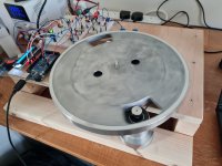
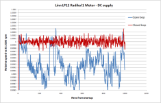
Speed tests on my Maxon DC motor

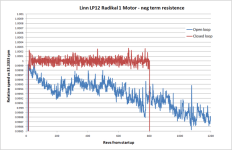
Hi all. I bought a RE max motor from maxon last year and have now got it running on a test rig I put together. The motor will be going in my LP 12 in due course and the rig is being used to develop the drive circuit, control parameters and to check all is well with the motor. In the rig the motor runs super slow with a drive ratio around 10x. There is no noise or vibration evident from the motor, which is good. The drive circuit is on a breadboard arduino controlled driving a voltage dac which provides 0 to 4 volts with a resolution around 20 bit so there is amble resolution to control the motor. Previous experience I have is that closed loop feedback is needed and negative terminal resistance, to both keep the speed accurate and to deal with stylus drag. Testing on this motor confirms the same. I have tested open and closed loop with and without negative resistance. The graphs show the effect on speed stability for these configurations. Note the drift in open loop is just over 1000 revs starting it off on point, so could degrade further thereafter.

The best accuracy is around plus / minus 0.01% at 33rpm. How does this compare to other motor types?

Attachments

  • 20230417_172027.jpg
    20230417_172027.jpg
    392.4 KB · Views: 204
  • PNG image.png
    PNG image.png
    48.8 KB · Views: 201
  • PNG image.png
    PNG image.png
    59.5 KB · Views: 199
  • Like
Reactions: alighiszem

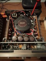
TEAC amp intermittent sound loss - what is wrong?

Dear all
My old(ish) TEAC A-H500i looses sound intermittently in both channels (at the same time).
First I was thinking speaker relays, but that I guess would be channel specific - or?
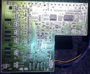
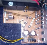
Then I saw this little fella, seemingly with a leak (or is it just glue?) According to the schematic it is on the “sub power supply pcb”.
I am not an expert and does not know what it does - anyone can help? Could this be it?
It is the one in the pictures - and link to service manual below.
If not it - what typically causes intermittent sound loss in both channels simultaneously? It is not a matter of speaker volume.
Thank you all 🙌🏻
https://audiocircuit.dk/downloads/teac/Teac-AH500-int-sm.pdf

Attachments

  • IMG_4689.jpeg
    IMG_4689.jpeg
    363 KB · Views: 82
  • IMG_4690.jpeg
    IMG_4690.jpeg
    488.6 KB · Views: 84

Rectifier Diode Replacement

Been a while since I've been here, just looking for a bit of verification on my current problem. I have an Auna Concept 620 which has been acting up lately, a lot of noise on the channels at times, audio just not coming out at random, other times audio being extremely quiet even with the sub volume at maximum, that kind of thing. I'm fairly certain the problem is with the 1N5404 rectifiers and considering they are on the edge am wondering if I should replace them with some 1N5408s to handle things better or if anyone could suggest something else? My only focus is with building something that is extremely robust - specs mean nothing to me if I won't have an audible difference.

Years ago I did some major recapping work on the sub where the primary capacitors blew out (I wasn't surprised to see this when I saw how severely under spec they were) so those got replaced with 2x 25v 125c RS brand capacitors and all other caps were replaced with Rubycon and Nippon Chemi-Con 105c so I know all of those caps are good but to be sure I did also inspect them, no leaking or bulging I can see. Any extra input is appreciated, I've attached a few images of the patient.

EDIT: On another note why is it the text size is appearing like it is set to extra large on the forum and it won't change when I select other sizes?

Attachments

  • IMG_20240731_001846_801.jpg
    IMG_20240731_001846_801.jpg
    737.3 KB · Views: 129
  • IMG_20240731_001909_845.jpg
    IMG_20240731_001909_845.jpg
    727.2 KB · Views: 131
Projects by fanatics, for fanatics
Get answers and advice for everyone wanting to learn the art of audio.
Join the Community
507,570
Members
7,877,302
Messages

Filter

Forum Statistics

Threads
405,738
Messages
7,877,302
Members
507,570
Latest member
speakerguyaz