ALFET give away follow up

Early this year there was an ALFET lateral giveaway made possible by Nelson. The give away consisted of two pairs of ALF08P16V and ALF08N16V – to build an F7 e.g.
All who participated have seemed to get theirs, so it's time for the last move.

There are still three (3) sets left.

As many of you already have a set, this time it will just be the three fastest, who will get these. Hopefully someone who hasn’t received a set yet.

The ALFETs are free, but the receiver will pay for shipping (5€/10€ depending country) via PayPal. I’ll give further details once we have the three names sorted out.
So the first three who want a set – please speak up! :violin:

- Jugi

DAC CEC DA1N

Hi guys
I have a DAC CEC DA1N I'm searching for service manual, someone have it ?
The display has low brightness someone know why ?

I would also like to make a modification, adding an external PCM, to get to 192 K. For this I provided an mp3 signal on the USB port of the DAC and I thought I would find the analog audio on pins 28 and 29 of the PCM, but measuring with the oscilloscope I find nothing.. and I don't understand why ... if someone can help me... thanks

Attachments

  • PCM.jpg
    PCM.jpg
    142.6 KB · Views: 91

A triplet of wire: Is twisting or braiding superior?

G'day Guys,

A question of construction theory here.

If was has a triplet of wires to be dressed eg: a centre tapped transformer secondary or the +Ve/GND/-Ve wiring from a PSU to an amp board.
Which is the superior approach.

A) To braid the 3 wires together: This looks to me like a superior solution to me as it appears to keep the wires more at right angles to eachother.
B) Twist all 3 together

I notice I don't see braiding in typical big brand AV amps that I salvage but I am guessing this is a cost factor.

845 tube orientation.

I am tasked with repairing a Chinese manufactured "Line Magnetic" valve amp with a bad channel - it uses 845s and 300Bs. The access to this elephant is from below, and my 1938 RCA valve book categorically states the correct operation of the 845 is socket down, bulb up. I realise filament sag could produce unwanted flashover if this lump was operated on its side but how about upside down?. I have to get in there with meter prods and scope probes. The incumbent tubes are Chinese. Ideas?.

For Sale Neuberger RPM 375 tube tester

For sale one of the best, if not the best, analog tube testers ever made. Neuberger RPM375.

Here are a few links about this tester:
https://tubedatabase.co/testers/neuberger-rpm-375
http://www.jacmusic.com/Tube-testers/Neuberger/370/index-Neuberger-rpm-370.html
http://www.jogis-roehrenbude.de/Roe...Pruefer/Neuberger-RPM375/Neuberger-RPM375.htm
https://www.radiomuseum.org/r/neuberger_roehrenmessplatz_rpm375rp.html

I have attached a few pictures of it. Tester is not mine, a friend of mine is the owner who is closing down his business.

Tube tester is in EXTRA good shape, almost no visible markings (there is one dent on the top cover).

Comes with additional tube socket adapters and original cards. It has connectors for external heater power supply (if needed).

It can test almost any audio tube there is. I own Neuberger RPM375 too and it tests GM-70, 845, VT4C with no problem.

Price: 3500€.

Location Croatia

Attachments

  • 1.jpg
    1.jpg
    529.6 KB · Views: 277
  • 2.jpg
    2.jpg
    499.2 KB · Views: 234
  • 3.jpg
    3.jpg
    527.1 KB · Views: 243

Micro stereo twin Silverstone 1301 7 pin

Hello. I was wondering of I could get some facts and opinions. First of all, this is my goal. Make a stereo amp to match the guitar I rewired to be stereo. One pickup to one channel, the other to the other. Standard Gibson theory there. I have built the stereo prototype and it sounds pretty good, but I still want to fine tune it, and possible tune it to reflect the strengths of the neck and bridge pickup respectively. At this moment I am still playing through each channel separately as it gives me some insight into the tonal changes I'm making to one in real time. Super handy.
As you can see in the schematic I have some thoughts and goals with the current design. Voltages are a little high, but I'm on the fence if this will be a real issue other than burning up tubes a little faster. They are easy to come by so no real issue there other than wasting tubes for what may not actually be any improvement in sound.
Questions: have I done anything stupid in the schematic? I know enough to get myself into trouble, and am working on learning enough to get myself or again. Suggestions are welcome as far as changes that people have tried and liked. Or, downright stupid things I have done and really need to change.
My other question is about a good way to mix a mono signal into the amp so it splits out both power amps (also in mono). In case I just want to play a normal guitar and don't need the stereo setup, but don't want to waste an entire side of the amp. There is a thread in here regarding this, but it rapidly moves away from what I think is useful for my purposes. My thoughts started with a phase inverter to split the signal, and it would probably work but there are phase reversal things I would need to do, etc. someone suggested using a cathode split (if I want a no gain buffered splitter), or a anode split of I want some gain from the buffered splitter. Placing this in front of both 6au6's seems smart to reduce noise. I'm pretty in the dark on this as design. I want to make sure I don't lose any signal in the split, if anything, maybe get a little more control because I would have two amps that sound slightly different that hopefully compliment each other. I don't have any intention of adding tone controls to either channel (yet), but I'm always open to good suggestions. Maybe a switch to move choose different coupling caps. This value did seem to make some big differences when I was fiddling with the first build. My transformer has enough juice for a couple more preamp tubes, but I'm thinking 6av6 or 6at6 for the buffer/splitter tube. I like the idea of keeping it 7 pin... don't look at the rectifier. it never happened 😀

So, after that long winded window into my thought process. Thoughts?

IMG_20240824_230821.jpg

Also, as a quick note. The Silverstone 1301 was a big inspiration for the design. Also Les Paul jr, champ 5c1, and magnatone aloha. Anyway, 6sj7/6v6 designs are way easier to come by than 6au6/6aq5, and they are pretty interchangable.

hifi 6J4 - 6P6P/6∏6∏ tube preamp

I have put together this preamplifier kit ,

I have a few questions on the grounding that is troubling me ..

The negative rail of the circuit is connected to the chassis that also acts as a ground for the transformer and the rca connection . basically they all share a ground that is connected to the chassis .

as far as I'm aware that is not a great idea and in my mind can't be that safe ? can someone please advice me on this matter

also one more point is that the earth in the iec ( 230 ac input is not connected in the schematic , I guess if that is connected to the chassis as well that will produce noise into the circuit )

Hopefully someone will be able to put my mind at rest

Attachments

  • IMG_1896.jpg
    IMG_1896.jpg
    1,014.7 KB · Views: 697
  • IMG_1898.jpg
    IMG_1898.jpg
    724.5 KB · Views: 642
  • $_10-5.JPG
    $_10-5.JPG
    157.9 KB · Views: 708

NAD 7400 Receiver goes into Protection Mode: Help with troubleshooting

Hi All,

I picked up a NAD 7400 that goes into Red protection mode. No blown fuses.
Tuner seems to be working fine.
Preamp and Amp are not connected.

I measure 74VDC (L to G and R to G) at the speaker terminal A.

No voltage on Speaker B terminals when Speaker B is On.

All transistors passed diode test ( no shorts found ) in situ.

Unfortunately I mis-diagnosed (measured an open circuit across CE - this is expected for BJT!) Q017 and Q020, Q023 and Q026 and removed them. I plan to resolder these.

Idle Current in the Right channel was high (around 27mV and rising) I managed to adjust it to 14mV per service manuals. Felt a lot of heat early from that side of the heatsink before lowering the idle current.

Idle Current in the Left Channel was adjusted to 14mV. It was close to the expected value.

Faults I’ve found so far
Speaker Relay RY001 (NO type Relay) is shorted( to be replaced by Omron Electronics G2R-2A-DC24 )

I’ve read 74 VDC (rail voltage?) at speaker terminals points to a short in the power transistors. I haven’t been able to find a short in the power transistors Q821-Q824, if I’m correct. Note the right channel in the schematics is a boxed abbreviated formed.

Can the RY001 short cause rail voltage at speaker terminal A?


Service manual attached. Thank you.

Attachments

ROSSO-18SW800

I have space to store 2 cabs. They should be able to be run from within this space locked into a dual opposed config or pulled out and arranged otherwise. This area is 4m wide, 50cm deep and 1m tall under desk area of a 4m x 2m x 2,4m booth. I think I can allow a pair of 18s under this desk. This booth will spend a lot of time on a 6m x 4m deck on a 6m boat and be open to salty air

This is a commercial project ina way as the craft or the pod will be for hire, or I might do a mobile CD/record shop when not on hire. Noise is not an issue, remote regional coastal town, can get away from residence and other water users. The craft is already built to survey, and now I am starting on the super structure and electrics

Power will be a pro grade class d module. These have integrated mains PSU and the design limits the power to 300wrms x 2 with either 8R or 4R. I can also either get the mono version of the same board, and this one does 600wrms/1400w dynamic into 4R

Power must be well-used. An arrangement of some lithiums and around 2kw of solar + an inverter generator to support that is feasible to me. I can series up in the bank to get to the minimum voltages needed for the universal PSU in the amp module. This bank will also run the main BLDC low speed cruise motor of the very efficient hulls

Would really appreciate some help in figuring out output potential based on the system power limitations. I am in sunny QLD and onboard volume would never be louder than safe levels, but the gear may get unloaded and transported for lil DJ gigs for lawn parties and such

https://www.wagneronline.com.au/attachments/Audio-Speakers-PA/sbacoustics/ROSSO-18SW800.pdf

Aleph 5 clone hum issue

I'm working on a Aleph 5 clone which is having hum issue, even without input cables connected. Upon tracing, I found the following waveform on the Gate of the lower half MOSFET, Is this normal or just due to poor power supply filtering? By the way, Purple trace is the Gate of the lower half MOSFET while Yellow is the Drain pin, aka the Output.

Attachments

  • IMG20240823215741.jpg
    IMG20240823215741.jpg
    388.3 KB · Views: 65

FREE loudspeaker damping / sound insulation material (like Rockwool)

Every couple weeks I get a delivery from Hello Fresh food company, they supply meal packs that include an insulating bag containing foods for the fridge.

As a consequence I have a few sheets of very nice materiel that I'm sure will be excellent for lining speaker cabinets.

Each sheet is 34 x 18 inches by 20mm thick. Please see pics. I have five sheets at the moment, one sheet would likely do a pair of bookshelf speakers?

These are free for anyone, just pay postage

IMG_0846.JPGIMG_0847.JPGIMG_0848.JPGIMG_0849.JPGIMG_0850.JPGIMG_0851.JPG
  • Like
Reactions: mdardeniz

Free aluminium panels

Aluminium panels of different thickness hopefully useful for heatsinks and custom chassis making. Unused and clean, still have protective film on one side.

Free just pay postage, the whole lot weighs 2KG but will send smaller bundles if needed. We all need a bit of aluminium now and then 😉

Attachments

  • IMG_0852.JPG
    IMG_0852.JPG
    306 KB · Views: 106
  • IMG_0853.JPG
    IMG_0853.JPG
    404 KB · Views: 102
  • IMG_0854.JPG
    IMG_0854.JPG
    467.2 KB · Views: 107
  • IMG_0855.JPG
    IMG_0855.JPG
    394.4 KB · Views: 100
  • IMG_0856.JPG
    IMG_0856.JPG
    600.2 KB · Views: 102
  • IMG_0857.JPG
    IMG_0857.JPG
    620.1 KB · Views: 102
  • IMG_0858.JPG
    IMG_0858.JPG
    336.2 KB · Views: 90
  • IMG_0859.JPG
    IMG_0859.JPG
    309.6 KB · Views: 76
  • IMG_0860.JPG
    IMG_0860.JPG
    335.2 KB · Views: 109

Port assisted subwoofer (PA)

I have touched that topic in few discussions, but never got enough good arguments, so here it is.

Modern subwoofers have enough motor force and displacement, that the bassreflex port on a ported bin is often almost not needed.
At least not fully in band. Now I use it just for cone displacement control, impedance shaping and cooling, otherwise it works for me almost out of band. As it is out of band, it can be small, it doesn't get the efficiency hit of small port, port noise is low, power compression is low, what's not to like?

Speaking about 18" subwoofer in a 95l/3.55cu.ft box, tuned at roughly 28Hz, used between 34 and 85Hz. I first did it with 21"s.

Seemingly it works great for its box volume. Only the price per woofer is somewhat higher.

Is here someone willing to discuss and object to get to the bottom of things? Why noone is doing it ever?

Many thanks.

Hello everyone!

Hello everyone.

I was looking for solution to fix one issue with my speakers and google said 'look at diyaudio'. Well, I checked the topic and, honestly, I don't know if it can help me, but I decided to post a comment. Since it doesn't let me post until I introduce myself, I decided to make a post here. To make things looks even worse for me, I created this account 4 years ago, but my post count is zero. I guess I tottaly forgot to introduce myself back then. 🙁
Even though I probably deserve to be kicked out for such thing, I hope that will not happen. I'm sorry guys!

I'm kindly asking if you can allow me to post comments on this board.

Thanks!

WTB 2.2 uF Film Capacitors (pair) in U.S.

Need a pair of 2.2 uF film capacitors for tweeter filter.

Voltage rating lower the better, new or used.

Paypal f&f, or if you want to trade, I have a ton of great film capacitors in 0.22 uF range and a ton of great tubes (12AU7/5814, 12AX7/5751, 12AT7, 6SN7(yikes), 5U4G, EL84/6BQ5).

The range of quality I'm looking for may include..:

Audience Auricap XO
Clarity Cap CSA, MR, CMR
Audyn true copper
Jantzen superior-Z or above
Jupiter or Miflex copper foil
Mundorf silver/oil or above
Rike audio Q-cap, S-Cap

Thanks!

Putting a Mouser order in, does anyone want a few parts?

Thought this is a good idea for members that just need a few parts without building an order to meet the minimum requirement for free shipping.

Anyone here can offer to add to their order or request parts to add to someone's existing order from Mouser / Digikey / Farnell

If you need a few caps or resistors, anything, let me know, I will be ordering soon.

🙂

DIY 3 Way-Loudspeaker with (maybe) Hybrid Crossover - BlieSMa+Purifi+miniDSP

Hallo guys,

this is my first thread after reading a lot for years on this website. So thank you for all your input. I dont speak english very well, so sorry for that. Now I want to design a new speaker and it should be my last one (at least for some decades)...

Points to consider:
  • My room is 5,5x4,5x2,6m. Listening Distance is 3,8m. My avg. (for me) loud listening at 3,8m is about 75-80db avg. with 85-90 db peaks. So the speakers should produce around 85db. avg. with 95-100db peaks, to have some headroom.
  • Musictaste is very wide. Only thing I dont listen to is stuff like heavy metal, large orchestras...
  • It should be a 3-way. No 2-way. No Di'appolito.
  • It should be activ with dsp.
  • It should allow to swap amps (so no Hypex but miniDSP)
  • It should use the T25B and M74B (I already have them)
  • Passiv Notchfilter will applied to lower distortion of the resonance peak of the M74B
  • It should have a nice dispersion, but dont use waveguide (because my son is 1,5y old and I dont want to have beryllium exposed to him (atm using a TW34BWNG in my speakers that have to go because of it)
  • Room is my homeoffice, music, homecinema, gaming room. So room treatment is an option. A little bit is done already and I will continue.
  • It should looks like build by a company, not a diy dude. Similar to Rockport Orion
  • It should cost overall arround 5-6000€ without amps.
  • Solidstate Amp for woofer and Tubes for the Midrangdome and the Tweeter.
  • It can be a bigger floorstanding speaker but no refrigerator.
  • I want to do some fancy stuff, even if it wont help much (Tuned Mass Damper at the top of the speaker)
  • Building time should be arround 6-12 months.

Tweeter is BlieSMa T25B crossed at 2750hz LR4 passiv.
Midrange is BlieSMa M74B crossed at 520hz LR4 activ (considering my needed max SPL and LR4 I think its fine).
Woofer will be most likely the new Purifi PTT10 crossed activ. Closed.
DSP will be miniDSP Flex or Flex 8 depending if I go with hybrid crossover or not.
Amp for the Woofers is a Accuphase 303-X (I inherit from my grandpa, so selling it, is more or less no option)
Amp for the Midrange I consider Tubelab SE with single-ended 300B
Amp for the Tweeter will be the same (if hybridcrossover) or a Tubelab SSE with single ended KT88 13-15Watt (to come closer to the max SPL of the M74B with 7-8 Watts from 300Bs)
I have a UMIK1 for measurements.

I dont know if I wanna go the Tube route with a Hybrid Crossover or not... Or just use 3 Amps... one less amp is tempting...

The plan for hybrid (of couse can only be finaled with enclosure build and measurments taken):

1700752505475.png


The plan if going full activ:

1700752650067.png


The enclosure plan:

1700752762459.png


1700752789641.png


1700754784981.png

Volume for the Purifi is exactly 24,8 L like Purifi datasheet and WinISD consider for 0,7. (You can get the mm² from sketchup for every object and than get the volume out of it. Volumen displacement from the Purifi is also considert.)
It maybe look like the enclosure for the purifi goes all the way to the top. But there is a plank under to M74B without any holes.

The bracing you can see in the pictures.

The front is in total 30cm wide. At the mid of the Midrangedome its 142mm wide and at the tweeter 88mm wide. C-T-C speacing between tweeter and midrange is about 1,2. (I follow some of HifiJims (and his friends) recommandations, I found at diy audio.

It will be build ot of 22mm good quality MDF and all parts will be glued with SikaBond T1 Purform. I have a fully equipt woodshop in my basement with a format circular saw, routers and so on. It will take time to do all the parts, but that's what make the design possible for me. You can print every piece in Sketchup in 1:1 and than use a router and flexible curve ruler to get it perfect. Than use the finished one as template for the same pieces.

The Tuned Mass Damper at the top will build out of steel with a total diameter of 110mm. It will be damped with small adjustable oildampers you can buy for RC cars. And it will be adjustable in height. I consider to make it out of aluminium and hollow to adjust the weight with damping oil. But this will increase the costs and chances are, the oil will escape.

I want you to ask, if my design is completely ******** or are there some mayjor design flaws?
Should I skip the hybric crossover and take a miniDSP Flex 8 with 3 Amps instead and for what reasons?
What I could maybe improve?
I just tried 2 passiv Notches for the M74B like found on this forum, but cant see much improvement over just one with slightly diffrent values. Is there a reason to use two? The Peaks are to close in my option to get much benefit out of it. Peak of resonance is -54 dB down at its highest point.

Thank you very much, be nice and greeting from Germany.
  • Like
Reactions: analogkid455

AER acoustic amp mains filter replacement

This is about an AER Compact Mobile2 acoustic guitar amp

Recently it started to blow fuses after a few hours of playing guitar. Until a few days ago that it started to blow them instantly when powering it up

There’s a mains filter inside the amp that it is shorted (fried). Bypassing it the amp plays just fine. But I don’t know if I can find the same one

Should I replace it or leave the amp without one? Is this a common 250V 4A mains filter. Do I have to find exactly the same one?


IMG_0091.jpeg

A Thread for those interested in PPSL enclosures

This is a new thread as suggested by Moray James. For Moray James: What I did was to simulate the enclosure with two speakers in Horn Response. I simulated it as you would an Altec A7 type of speaker but with a front chamber on the horn. This front chamber would be the plenum if I am doing it right. The plenum opening was the horn throat. I rounded the opening a couple of centimetres and used this as the horn. I did do the combined sim to take into account the vents. As I said in the other thread, I don't know if this is anywhere near accurate.

Any input from those who have done this type of design would be most welcome.
jamikl

Hello members, i am "Pioneer_Exclusive" and i am new here!

As a newbie, I would like to introduce myself briefly:

I have been a HiFi enthusiast since 1978 after buying two Pioneer devices (SA-9500II and TX-9500II)!
The two devices formed the basis of a collection that has since grown, mainly of Pioneer devices and a few other manufacturers.
As a long-time electronics hobbyist and a qualified electrical engineer, I see myself as being able to repair everything myself and, if necessary, develop everything myself.

At the moment I am busy with a replica project "TAD TSM-2" and that is exactly why I ended up here.
I hope to find some additional information or to be able to give information to others!

I look forward to a lively exchange with you here in the forum -
best regards
Pioneer_Exclusive
(Juergen)

How can I measure the parameters of an electret condenser microphone professionally? (lavalier)

I want to measure the parameters of a lavalier microphone like this one:

Sin título-2.png


The data I am most interested in are sensitivity, s/n ratio and frequency response.
To measure the frequency response, do I need an anechoic chamber?

What particular equipment do I need for a scientific measurement?

Thanks.

Tool to measure output level

Hi everybody
I recently got a vintage amp and have been using it for a couple of months now. It works and makes a very pleasant sound to my ears. Though there is one concern. Almost all the time I hear that one channel is slightly louder than the other. Of course, it may be my hearing. I did the typical cleaning of the unit, including the balance and volume control pots and bias adjustment.

Question: Can I use a tool/equipment to measure the actual levels of the signal coming out the amp to both channels, to confirm or negate my subjective and personal suspicions?

Thanks.

Merlin RIAA Preamp

I have been very interested by Merlin book on Tube Preamps and I decided to build the RIAA amplifier, however I decided to replace the cathode follower in the output stage by a MOSFET source follower (I already used this solution in a Baby Huey amplifier with a very good result) to save one tube and because I wanted to avoid the big voltage difference between the heater and the cathode of the output tube...
As I don't like point to point soldering, I have started to design a PCB. If someone has any suggestion about this project, please let me know.

Do you know if the PC900 can also be a good device for this project ? The pin-out is not compatible however 😡

Cheers,
Marc

Attachments

What is this technique called?

Looking at some photos of open baffle stuff and this one comes up... One calls it slot loaded, another calls it horn loaded.

Technically I suppose I'm curious of:

  • what the ring type relief is called?
  • does the phase plug simply avoid the flat slapback of leaving that central portion untreated?
  • is this slot or horn loading?

Maybe it's neither etc, I was just curious "what the folks at diyaudio called it" etc. Thanks

Attachments

  • img_1_1724339514059~2.jpg
    img_1_1724339514059~2.jpg
    63.2 KB · Views: 242

For Sale Babelfish XA252

-SOLD-

Built using full kit from ZenMod with Antek AN-10425 transformer, Randy’s W12 CRCRC PS board, DIYAudio Softstart, WBT binding posts and RCAs, KimberKable wire and custom 4U 500mm chassis with UMS hole pattern. Sounds fantastic. Only selling because I purchased a PassLabs Int-25.

Asking $1,000 with shipping within continental US included.

Attachments

  • IMG_0863.jpeg
    IMG_0863.jpeg
    597.2 KB · Views: 221
  • IMG_0864.jpeg
    IMG_0864.jpeg
    642.5 KB · Views: 204
  • IMG_0865.jpeg
    IMG_0865.jpeg
    473.8 KB · Views: 203
  • IMG_0866.jpeg
    IMG_0866.jpeg
    558.4 KB · Views: 188
  • IMG_0869.jpeg
    IMG_0869.jpeg
    579 KB · Views: 186
  • IMG_0870.jpeg
    IMG_0870.jpeg
    607.1 KB · Views: 183
  • IMG_0545.jpeg
    IMG_0545.jpeg
    693.1 KB · Views: 203

Highly confused about Texas Instrument TAS Class-D IC and LC output filter requirements for post-filter feedback

Hello everyone,

I put some effort into designing an output filter for a class-D IC. Here I am using Coil Craft's and Murata's SPICE models to calculate the filter with an 8 Ohm load.

Lines:
  • Red line is the capacitor impedance
  • Green line is the inductor impedance
  • Purple line is the filter response
Screenshot 2024-08-22 at 12.35.03.png


Filter:
  • -3dB cutoff is around 25kHz, just outside the audio band
  • The filter works until about 10MHz where the parasitics of the components have a resonance.
  • Sure the values can be tweaked, but this is not a bad starting point for now.
Post filter feedback

The IC that I am using TAS2780 has a post filter feedback (PFFB) feature and I thought that would be good to use to keep the THD as low as possible. So I started reading about the PFFB requirements.

1724327511815.png


It seems crazy to me to specify the filter cut-off frequency to be greater than 10MHz when this device is switching is 380kHz.

What could they mean?
  1. The rise/fall time of 1/10MHz = 100ns. So maybe if the rise/fall time of the IC is around 10ns or less, the filter could filter that out?
  2. The cut-off frequency they mean where the parasitics break the filter? This is around 10MHz for the L and C parts I am using.
They have an application report SLOA260 that was not that helpful, if focuses on using ferrites.

Questions
  1. Can anyone experienced with Class-D and filter let me know if a -3dB cut-off just outside the audio band is sensible?
  2. Has anyone used TAS ICs from Texas Instruments before, or the TAS2780 specifically? Can you suggest a sensible filter with or without the PFFB feature.
  3. What the hell are they talking about in the data sheet and application report when they specify the cut-off must be greater than 10MHz?

Help for 2 way build with TAD2001 on top

Hi All,

I am going around in circles trying to decide how to proceed on my next build. I have a pair of lovely TAD2001s coupled to a beech plywood tractrix horn that I have made - very happy with the sound at home. Below it I am using a Supravox 285 in a ported enclosure as a 2 way monitor style. They seem to work very well together but the low end is limited in extension and the output of the woofer is slightly limited for high spl fun now and again albeit super detailed and fast in mid bass. The crossover is 2-way 2nd order at 800hz - that suits my horn fc and what TAD recommends. Using active crossover right now.

So I am now thinking how do I take this to the next level to accommodate more output without ruining quality but also being durable. I was considering either going for an alternative single 12” driver or building a new cabinet with MTM design using twin 12s per side OR going for a single 15” like the JBL 2226H. I did loads of Hornresp simulations of different drivers but can’t make up my mind. The 2226H in every sim I did didn’t really get adequately to 800hz. 700hz looked max but I realise many use it above that.

I do want to be able to play this system really loud on occasion so durability of woofers is also important. I am not too fussed about content well below 40Hz as I can augment with sub. Importantly I do want high efficiency.

Any advice much appreciated!

2SC3381 and 2SA1349 replacements

Hi y'all! New here but not entirely new to DIY audio projects.

My friends and I are looking for replacements for Toshiba 2SC3381 and 2SA1349 BJTs. There are forum posts with single package replacements over the years, but even those replacements are out of production. I'd like to avoid eBay or sketchy transistors if possible. If I'm not mistaken, the parameter we are having difficultly with is the DC current gain (hfe) classification we're looking for a minimum of 350.

Any help is appreciated, thank y'all!

Greetings from Italia

When I have reached retirement, I can finally dedicate myself to diy audio, which I have been doing for 50 years now, especially in speakers, both on magazine projects and designed by me, also thanks to the forums on the web.
To write in English I have to help myself with the automatic translation of the web, so sorry for mistakes.
I have also been passionate about environmental acoustics for many years, because of a friend acoustic engineer specializing in concert halls, acoustics in public places, companies etc.
I finally made a special listening room of 7x5x3 meters designed and evaluated by him with a final written report. This is because for years I have been convinced that 50% of the final quality depends on the environment, especially for the bass and high levels of listening that I like with the right music.

Again greetings to all.

Modify integrated amplifier as preamp

Hello,

Im new here, hope this is correct subforum. I plan to test my working integrated amplifier Marantz PM-750 DC, want to try their preamp.
I already research that its doable. I want to make sure, is this the correct signal path? Here is the zoomed schematic, and below is full schematic.
What i read is right before power amplifier board to make an output.

Schematic_zoom.png


Schematic.png


Red is right channel line
Orange is left channel line
Blue is where i plan to cut.

And second question, if i plan to test the amp, should i put E-CAP bipolar 10uF 25v in series each channel, just like what i see in my Marantz 1180 DC right after "MAIN IN"?

Thank you

DFPlayer output as Line-Out

I'm designing something in which audio plays a small but vital part. A DFPlayer module will be used to play a short audio file and the output will feed an external PA system. The easiest way to do this is to use one side of the BTL outputs as a Line-Out rather than create a balanced-to-unbalanced converter

With this arrangement, one output pin will be open and the other pin will face an unbalanced high impedance load to ground. Is there any possible issue with this arrangement, in terms of stability and distortion? None of the documentations I've seen about DFPlayer is very forthcoming with this kind of information.

DFPlayer line out.png

Atention to Classe CDP.3 owners

As the DAC nearly newly released maybe somebody will have benefit for it. There was error during asembly and many (I checked photos in internet- same error) or probably all cdp.3 have wrong capacitor soldered in filter - 15nF instead 1.5nF. I accidely found after tried listen to it. high frequencies was rolled of quite badly at 10khz already -3db

once replaced sound become transparent and airy.

i have expierended same ~2011m on m2tech evo usb conveter were highs had -3db at 15khz and 1.5db at 8khz

hope this helps

Attachments

  • genue.png
    genue.png
    2.2 KB · Views: 67
  • Like
Reactions: merlin el mago

Help with Sanwu PBTL

Ok as the title says I have the red Sanwu tda7498E version from Amazon. I soldered the 4 jumpers together on the bottom of the PCB and input a signal into the LEFT RCA only from my low pass filter preamp. I also put both dip switches that control gain to the max setting of 36db and the output level is approximately half of what I get in btl mode! I usually use this amp in btl with (2) 4-8ohm 2-way bookshelf speakers and it gets very loud. I measured 26vac average clean with my oscilloscope while using a 34v 10a PSU. While the amp is in PBTL I'm using a 4ohm GRS 8" high excursion sub from parts express. What's going on, am I doing something wrong?

Does anyone have experience with passive radiators and WINISD?

I am trying to mate some SB Acoustics drivers and passive radiators together. They are literally made for each other, however, when I enter it into WINISD it is simulating what I assume to be an improper frequency response. Part numbers below:

Driver:

5×8″ SB15SFCR39-4 / Paper
https://sbacoustics.com/product/5x8in-sb15sfcr39-4/


Radiator:

5×8″ SB15SFCR-00 / Paper
https://sbacoustics.com/product/5x8in-sb15sfcr-00/


These are small 5x8 drivers so I would think they wouldn't require a huge amount of space.
Can I get a sanity check? Yellow is the passive radiator. Blue is it vented. The vented looks great. I would think the passive radiator made for this driver would look similar.

Attachments

  • Screenshot 2024-08-22 132412.png
    Screenshot 2024-08-22 132412.png
    25.3 KB · Views: 61
  • Screenshot 2024-08-22 132401.png
    Screenshot 2024-08-22 132401.png
    28.5 KB · Views: 61
  • Screenshot 2024-08-22 132348.png
    Screenshot 2024-08-22 132348.png
    35.1 KB · Views: 63

The Martin Mars

The Hawaii, has left her home on Vancouver Island for the final time.
https://www.cbc.ca/news/canada/british-columbia/hawaii-martin-mars-last-flight-1.7291472
I had the pleasure of visiting the second to last unit, and parts of others, (the only flying one was anchored off shore), on a trip to Vancouver Island about a dozen years ago with then still somewhat spry Father. He left in 2015 but having him there, that day, that time, is something I am so glad we did. We had a couple of extra hours before the ferry took us back to the mainland, so what better way to spend time with your aging Dad, than doing things that had a big interest for him.

I did not want to be the 'Cat's in the Cradle' son.

Sorry for the picture quality. Maybe, it's just me, getting a little blurry eyed. 😉
She really was the queen of her skies.

Attachments

  • IMG_8151.jpg
    IMG_8151.jpg
    245.5 KB · Views: 117
  • IMG_8155.jpg
    IMG_8155.jpg
    149.4 KB · Views: 117
  • IMG_8156.jpg
    IMG_8156.jpg
    151.1 KB · Views: 116
  • IMG_8158.jpg
    IMG_8158.jpg
    56.8 KB · Views: 118
  • IMG_8163.jpg
    IMG_8163.jpg
    108.8 KB · Views: 116
  • IMG_8164.jpg
    IMG_8164.jpg
    166.7 KB · Views: 114
  • IMG_8165.jpg
    IMG_8165.jpg
    79.3 KB · Views: 112
  • IMG_8167.jpg
    IMG_8167.jpg
    116.8 KB · Views: 113

One single driver with several frequency responses. What the heck?

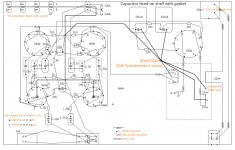
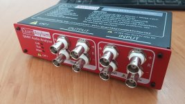
I heard from a discussion about driver measurements. The topic was about generating xover filters, and about the best compromise measuring distance. I consider this an interesting playfield, and this motivated me to perform some simulations. It’s all about anechoic, direct sound and the influence of the measuring distance on the baffle diffraction step (BDS).

Assume a linear monopole point source on a circular baffle. When the pressure wave reaches the rim of a baffle, its’ room geometry changes from half-space to full-space. This is a change by a factor of 2.

In the time domain, this change theoretically will cause a negative impulse. As the room geometry changes by a factor of 2, the magnitude of this negative impulse might be half the amplitude of the initial positive impulse. In the frequency domain the response will show the well-known BDS and some comb filtering towards higher frequencies with a first minimum corresponding to the baffle width. This is widespread common knowledge.

Most models and graphs for the BDS assume an observation point in infinity. For the infinity case, in time domain the negative impulse occurs after the time needed for the soundwave to propagate from the centrepoint of the baffle to the periphery.

Instead, theoretically approaching the observation point to null distance from the baffle plane into it’s centre will double this time: The sound has to travel to the periphery first, and then return to the centre where it gets assessed. In time domain the negative impulse occurs delayed by a factor of 2 compared to the one assessed at Infinity. In frequency domain, this leads to a combined squeeze/shift of the typical frequency response along the frequency scale. The first minimum of the comb filtering pattern will occur one octave lower than in the infinite case.

In analogy to these both extreme cases, it becomes evident, that even without taking any room response (such as first reflections, echos and the like) into consideration, measuring at 1m and listening at 3m will not be the same in terms of frequency response. Therefore, relying to a measurement from 1m distance to optimize a set of xover-filters, and then later on listen to the result at 3m may lead to a mismatch between the filters and the actual frequency responses and thus to an awkward and unwanted experience.

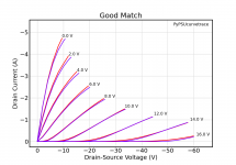
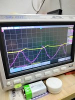
Let’s do some simulations to explore this one. For the following graphs sampling rate was set to 192kHz. For the first three graphs the baffle diameter was assumed to be 34.3cm which corresponds to a wavelength corresponding to a frequency of 1kHz.

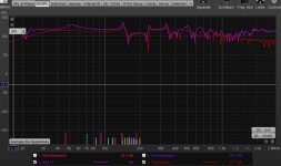
Curves show measurement distances of
green: 0, theoretical measure flush on the baffle's center, e.g. spot-on the point sound source
brown: 1 == 0.343 measuring distance (in baffle diameter length, 1 == 34.3cm)
blue: 2.9 == 1.0m measuring distance
grey: 8.7 == 3.0m measuring (=hearing) distance
black: Infinity theoretical measuring distance
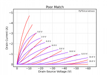
Red individually shows the resulting magnitude difference between two test distances.

The time domain graph. The negative impulses of the baffle diffraction occur with different delays from the initial positive impulse:

T34.png


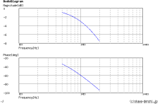
Frequency domain: Red shows theoretical null distance vs. infinity BDS model distance

M34_100-Inf.png


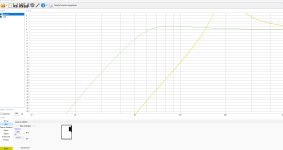
Frequency domain: Red shows the frequency response difference between 1m vs. 3m measuring distance:

M34_100-300.png


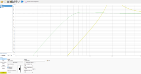
Frequency domain: Difference 34.cm vs. 3m measuring distance … measuring very close is no good idea at all …

M34_034-300.png


And now, what about a more narrow baffle at 17.15cm diameter, e.g. half the size of the former one?

Time domain for 1m vs. 3m measurement:

T17.png


Same 17.15cm baffle, but in frequency range
Red 1m - 3m
Blue at 1m (5.8 times the baffle diameter)
Grey at 3m (17 times the baffle diameter )

M17_100-300.png


Small baffles, as expected by geometry/trigonometry logic, show less severe shifts at the typical measuring/listening ranges of 1m/3m than large baffles. It’s evident, because relative to the smaller baffle width, the distance/bafflewidth quotient get bigger. By the way, this might be a contributing reason why baby baffles sound more pleasing at any listening distance than adult ones.

Caution: Take all these simulations all with a grain of salt. These graphs show a theoretical workout of the subject, highlighting a possible issue. In practice you will ideally not have to deal with central point sources on circular baffles. But the take-home message seems clear: Do not measure too close in a false idea to best possibly exclude room interferences. This will jam your measuring validity range. The closer you measure, the messier the result gets for more distant locations. Same goes not only for x-over filters, but also for whole speaker system measurements.

Guitar Pickup switching system (using microcontroller)

Dear forum,

It is not a new idea, but everywhere where I saw something like this in the internet, it was never accomplished and the thread just ended up with no conclusion.

I want to raise a topic of a Guitar pickup system, where it is possible to connect them in any possible way (parallel, series, out of phase) with the help of a microcontroller onboard. This was done ones commercially by a Music Man company in their Reflex Game Changer guitar. I was thinking on what it takes to re-make something similar.


QUESTIONS

  1. As the guitar pickup output has high impedance, and in general guitar output has a high impedance, when wired canonically of course, I am very concerned about preserving this high impedance (if it is at all possible). As I understood, the analog switch, even with the lowest on-resistance will affect the output of the pickup and lower the output impedance.
    Q1: is it indeed like that and it is not possible to carefully select such components, so the original impedance of the pickups is preserved?
    Therefore, I see recommendations to use a buffer, e.g. op-amp, between the pickup and the switch, so the sound characteristics are preserved, but the signal is then "transformed" into a low-impedance environment. As I understand, this is a compromise to use digitally controlled switches. Moreover, some people prefer the guitar to output a low-impedance signal, as it eliminates a lot of problems with long cables, nasty guitar pedals, etc. In other words, there's an opinion, that low impedance is not bad at all.
    Q2: if the buffer is needed, is it enough to put it after the pickup before the first switch for every pickup? Or does this chain needs more buffers?
  2. Buffer: I know there are a lot of buffer options with JFET and other transistors. I think the choice here is: as smaller as possible, as less components as possible, the best sound preservation. For me it looks like Op-Amp is the option to go, even if it can be costly.
    Q4: what do you think?

Hello from Cannon Rocks, South Africa

I've been lurking around for quite some time now, I guess introductions are in order. As the title says, I'm from sunny SA. Got my HiFi feet wet recently when I bought a secondhand pair of KEF Coda 7's. I'm powering them with a Aiyima A07. The plan is to upgrade all of that as time allows. I enjoy listening to blues and a bit of jazz but still have a lot to learn about music.

Using LM317/337 to power low current stages off of main +-40V supply

I picked up a nice looking old 70's Kenwood that was missing parts, so I retrofitted it with a new PS/amp/preamp and I'm trying to come up with the best way to power the legacy tuner/phono stages in the unit. I'm very tight on space so would prefer not to add another transformer.
3 voltages are needed, +28v, -19v, and 13.5v.
I was considering an lm317HV/lm337 connected to the main +-40V supply to derive the +28v & -19v.
For the lm337 I saw this thread which uses a zener across the input-output so you can use it with higher voltages.
For the +13.5v I was considering using the positive half of the preamp supply but wondering if pulling from half the supply is a bad idea.
I'd like to keep the legacy components functional, even though realistically they will probably rarely if ever be used.

Attachments

  • KR3090 schematic-edit.jpg
    KR3090 schematic-edit.jpg
    682.8 KB · Views: 132

usernames, passwords and scams

I got scammed a few weeks back on face book market place.

Recently I found my email address and password got hacked.
Stupidly I used same password for lots of different websites.

I managed to get in quick with ebay and changed my email address and password before any money was taken.

I got caught out on Ali Express as theye didnt ask for cvv number before making a payment.
I was down about £300 which HSBC are sorting out for me. Again got in quickly to block the card but still some damage done.

I guess the lesson is use different passwords for each website you buy from or use.

Shorted Harman Kardon main board (I think)

Hi everyone I'm triyng to repair an harman kardon ts2bq/ts11/I don't know how many name this subwoofer has...
The first problem was literally a hole big such a finger in the amplifer board with shorted mosfet and blowed up capacitors. After having fixed the amplifer board I've tied to turn it on, the results are two shorted mosfet and another problem.
After several tests with the tester I'm stuck, if I put the tips in the positive and negative of the diode bridge for a few seconds the tester tells me that there is a short circuit, after the value continues to rise up to 1560, after a few minutes it goes back to how it was before. I did these tests by removing the diode bridge (to check that it wasn't that) and removing both the amplifier board and the jack board.
What component can have this behavior? Could someone help me?
This is the datasheet

Thanks

Martin Logan ESL upgrades

The cheapest Martin Logan ESL is a good value for the money. Can we make it a little better with a little effort? These are the things I successfully tried:
  1. Linear power supply. You don't even need to buy that fancy 'audio' power supplies. A normal, stabilised, linear (with a transformer) power supply also helps a lot. I tried something for $10, 15V, 1A, with a 5.5/2.1mm DC plug, plus in the middle.​
  2. Bass is probably the part where ML ESL is the weakest. We can at least try to mitigate some problems here. Adding a weight to the speakers could help. I had granite coasters laying around, that almost fitted perfectly. Also, it seems that the enclosure has some resonances, so I added self adhesive bitumen pads inside. That was very helpful for quality of the bass. When being at it, changed the filling to wool.​
  3. Unfortunately I couldn't place the speakers far enough from the wall. The back wave was messing the sound too much. Ideally it should be diffused behind the speakers somehow. Probably with some acoustic system on the wall. Anyway, I couldn't find anything aesthetically pleasing enough. I had to damp the back of the panel with an acoustic mat. It worked well for the purpose.​
  4. Next step was checking if bypassing the caps in the crossover can be beneficial. The result was also promising. Caps bypassed with 1% of the original values. It helps with resolution and smoothes the highs.​
Do you have any other modifications that can be easily tried?

Attachments

  • IMG_0499.jpg
    IMG_0499.jpg
    161.2 KB · Views: 609
  • IMG_0500.jpg
    IMG_0500.jpg
    176.4 KB · Views: 653
  • IMG_0502.jpg
    IMG_0502.jpg
    126.7 KB · Views: 782
  • IMG_1363.JPG.a8919d3316b1aec020cb87e2cdc017d4.JPG
    IMG_1363.JPG.a8919d3316b1aec020cb87e2cdc017d4.JPG
    156.9 KB · Views: 590
  • IMG_1364.JPG.8ed0103b7b823bad4566668744a6718c.JPG
    IMG_1364.JPG.8ed0103b7b823bad4566668744a6718c.JPG
    105.2 KB · Views: 564
  • IMG_1834.JPG.743199108f4dedf6d46790850a75bb47.JPG
    IMG_1834.JPG.743199108f4dedf6d46790850a75bb47.JPG
    79 KB · Views: 557
  • IMG_1835.JPG.75c95042b63a9a43b6420ac39aa4d4ea.JPG
    IMG_1835.JPG.75c95042b63a9a43b6420ac39aa4d4ea.JPG
    102.3 KB · Views: 556

For Sale Selling: Sony VFETs / SITs 2SJ28 and 2SK82 (fully tested with curve tracer and Vgs data)

Edit March 2024: You want parts? Read this post carefully. Do what it says, all of it. Otherwise your PM might not get an answer.

I have a bunch of Sony VFETs 2SJ28 and 2SK82 parts for sale. All parts were tested for gate-source voltage (Vgs) at ±1.6 A drain current (Id) and ±20.0 V drain-source volatge (Vds). There are full curve traces for all parts (Id vs. Vds at Vgs = 0, ±2, ... , ±16 V).

The parts were matched by "curve matching" as explained here.

If you are interested in getting some of these parts:
  • Take a look at the parts lists with parameters (Vgs, gm, μ), curve matching, and curve plots:
  • Select your parts:
    • I recommend to first look at the curve-matching list available at the links above. In short, a low delta-Vgs means a good overall match. Read this to learn how the curve matching works.
    • The parameters list may also be interesting.
    • This post may be useful to learn about parts matching based on their curves.
  • Send me a personal message (PM) here on diyAudio with your part numbers and complete contact details (see below) and I will reserve the parts for you
  • Payment: PayPal preferred
  • Once I receive payment, I will send the parts to you
Price per part is CHF 135.00 CHF 170.00
Shipping and handling is CHF 22.00

Contact details (I need all of this, and I may ignore reservations with incomplete information):
  • Shipping address (first and last name, street / building / number, town, ZIP, country)
  • Your telephone number (including country code)
  • Your email address

Attachments

  • example_2SJ28_good_match.png
    example_2SJ28_good_match.png
    32.2 KB · Views: 249
  • example_2SJ28_poor_match.png
    example_2SJ28_poor_match.png
    35.5 KB · Views: 263

Adding a Headphone Amplifier Circuit to a DIY DAC

Hello, I recently made a PCM1794 DAC. The output of the I/V circuit was set to 2Vrms. I'd like to add a headphone output jack and a volume knob here. NE5532 based headphone amplifier Are there any problems driving low-impedance earphones or suitable headphones such as HD600?
Experimenting with this circuit in LTspice, I think the power is too large.
And why do you need a high-pass filter?
1724316735800.png

For Sale DCG3 + DCSTB fully built and working

Since I decided at the last stage for another preamplifier, I am forced to sell this one. It's definitely a great preamp but for capacity reasons I'm forced to sell it.

The preamplifier has a set bias voltage of 170mA, ideal for low-ohm headphone. All parts are genuine from @Tea-Bag

Sold only together DCG3+DCSTB. (Price is negotiable.)

Additional parts I can offer:
  • inteligent on/off module
  • Large heatsinks with pre-drilled holes.
  • 2 pcs toroidal transformers from (toroidy.pl), 50VA, 240V, 2x18V
  • Khozmo attenuator 25K
  • AC Power Entry Modules Shurter
I only send within the EU. (paypal, wire transfer)

I can give a discount when you buy all parts.

Attachments

  • IMG_20240721_124008.jpg
    IMG_20240721_124008.jpg
    318 KB · Views: 132
  • IMG_20240721_124023.jpg
    IMG_20240721_124023.jpg
    385 KB · Views: 126
  • IMG_20240721_124049.jpg
    IMG_20240721_124049.jpg
    249.8 KB · Views: 128
  • IMG_20240721_124109.jpg
    IMG_20240721_124109.jpg
    376.9 KB · Views: 120
  • IMG_20240721_124133.jpg
    IMG_20240721_124133.jpg
    163.8 KB · Views: 124
  • IMG_20240721_124148.jpg
    IMG_20240721_124148.jpg
    280.2 KB · Views: 123
  • Like
Reactions: passive420

So I was looking at Aliexpress for something else and I came across an IRS2092 implementation with balanced connection?

I had a look at the IRS12092 datasheet it seems to me there's only 1 input.

Also the amp seems to use 2 opamps to convert unbalanced to balanced (or maybe I misread the PCB labels and that it converts balanced to unbalanced). thoughts? Thank you.

https://www.aliexpress.com/i/32884021133.html

Speaker building parts/tools in carry on luggage

I’m visiting a friend and his boys…they are in the early stages of building a speaker…it’s their first one and they don’t have hardly any tools.

I have a twenty year carry on luggage only streak I don’t want to break and would like to bring the following with me….any problems?

Mylar dome tweeter
Speaker wire
Speaker terminals
Aux extension (3ft)
Aux to RCA
Wire stripper and crimper
Soldering iron and solder

The ones I’d think they might have issue with are the soldering iron and the wire stripper/crimper….but please inform me if there are others…or if you’d think no problem with any of the above.
Projects by fanatics, for fanatics
Get answers and advice for everyone wanting to learn the art of audio.
Join the Community
507,581
Members
7,878,093
Messages

Filter

Forum Statistics

Threads
405,780
Messages
7,878,093
Members
507,581
Latest member
Wandaru