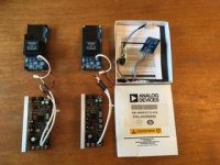
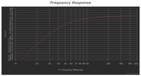
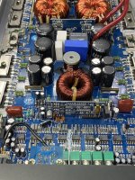
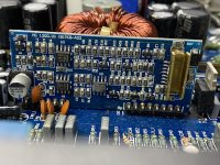
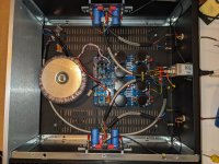
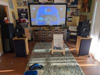
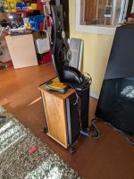
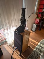
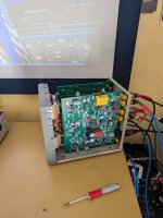
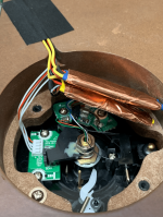
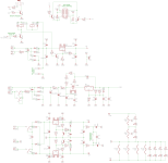
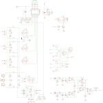
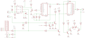
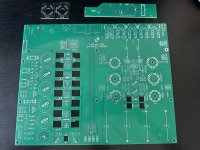
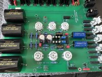
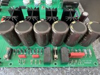
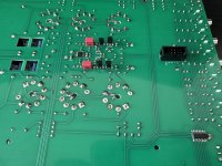
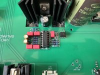
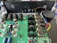
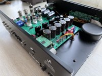
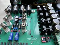
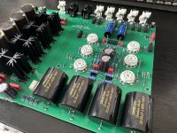
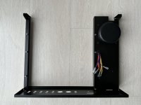
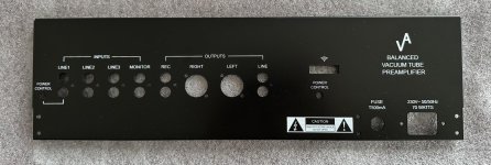
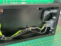
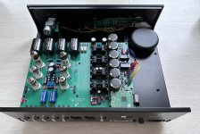
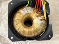
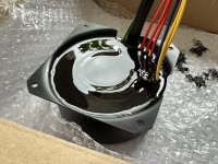
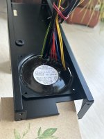
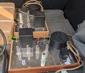
Any help upgrading my NHT Power2 that contains 2 Icepower 500As and a single 500ASP?

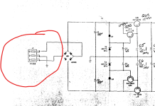
Hello, several years ago, I purchased an NHT Power2 on clearance, fully aware of its unusual design. Instead of using a single Icepower 500A along with the 500ASP to achieve the same results, NHT used the power supply on the 500ASP to feed two 500A modules and rated the amp at 200W x 2. I've learned that Icepower released a 1000A(EDIT: I meant 1000S. Sorry for the confusion) module that's essentially a 1000W power supply.

I'm interested in obtaining one of these modules to power the two 500A modules and potentially create a third channel to utilize the 500ASP. This modification could transform the amp into a 3-channel version, possibly increasing the power output to 250W per channel if the 500ASP's power supply was indeed limiting the existing design to only 200W per channel.
Although I have an EE degree, I've never worked as an engineer. Nonetheless, I believe I could handle following a wiring diagram and soldering connections. However, I don't know where to find the wiring diagram for this specific modification, and I would appreciate tapping into someone else's wisdom who has experience with IcePower modules. Is there a resident expert who would be willing to help?

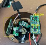
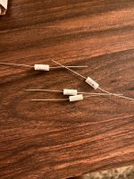
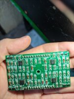
Which TPA3116 is this?

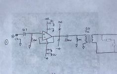
Recently my old TPA3116 gave up and I wasn't able to fix it, so I bought a new one but unfortunately theres an audible hiss and a pop on turn on. So I wanted to do the gain mod but I also stumbled across that I might also need to change the input capacitors if I change the gain. I'm not very informed as you can tell so I got couple questions if you could help.

  • Is there a common name for this board so I could search around for mods for it?
  • Could someone point at where the input capacitor should be? Should I actually change it if I change the gain?
  • Where are the Master and Slave gain resistors?
  • Should I change the 50K pot?

Thank you!

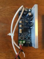
IMG_4506.jpg

For Sale Two 4-Channel DSP boards with programming adapter for Sigma Studio

I have two 4-channel DSP boards left from an active speaker project

including psu and programming adapter for sigma studio


I bought the boards a few years ago as OEM from an german speaker manufacturer.


The DSP Chip is from the ADAU144x line with 172Mhz. So you could use IIR and FIR Filters.

ADC is a PCM4201

DAC is a PCM4104


Every board has 1 balanced analogue input and 4 balanced outputs

There is also a digital input and output, so you could pass the digital signal from one board to another and could choose which board is left/right


I think about 400€ plus shipping for both boards with psu and programming adapter

If you have questions let me know.


Best regards

Daniel

Attachments

  • DAE6-BDE2-CCCE-4654-AD21-A19-C6-B6-F2-A52.jpg
    DAE6-BDE2-CCCE-4654-AD21-A19-C6-B6-F2-A52.jpg
    19.6 KB · Views: 53
  • 85-B79-B4-A-007-F-4-BB8-80-BD-7-F60779-C8687.jpg
    85-B79-B4-A-007-F-4-BB8-80-BD-7-F60779-C8687.jpg
    10 KB · Views: 54
  • 2-D938-C4-C-E34-F-49-AA-9738-51-CC50-A1-CC91.jpg
    2-D938-C4-C-E34-F-49-AA-9738-51-CC50-A1-CC91.jpg
    22.8 KB · Views: 56

Crossover advice please

IMG_7554.jpeg
IMG_7559.jpeg
1db66722-cca0-43cb-97b9-996c1b578065.jpeg
Hi guys .
I acquired a nice pair of Ruark Accolades yesterday.
Currently the passive crossovers are external as they were once converted to active ( now passive)
I do intend to put the crossovers back inside or make a nice box and keep them as external.
I have replaced the Alcap capacitors this morning with some Mundorf 5% , looking at the crossover are there any further improvements to SQ that could be made ?

Also I managed to get a schematic which shows 16uf caps at position C5 but there aren’t any on these crossovers ? ( could they be inside ? )
IMG_7560.jpeg

Thinking of applying Linkwitz Transform to my speakers

I have been building my large bookshelf loudspeaker project. I use 10” car audio subwoofers as the woofers. I built closed enclosures with Qtc of 0.5 for them. They offer decent bass response. However, I think it’s a bit too low efficiency. So, I’m thinking to apply the active bass equalization circuit to them.

Firstly, I’m not sure if I could call it as the “Linkwitz Transform” circuit.

Secondly, I’m not certain which frequency should be the center point. And how much level for the boost? If I’m not wrong, the Qtc of 2.0 would yield a boost level of +6dB.

Consequently, finally, should I build the Linkwitz circuit with Qtc of 2.0 at the box resonance, 38.5Hz regarding the attached?

Attachments

  • s10.pdf
    s10.pdf
    54.2 KB · Views: 46
  • IMG_8875.jpeg
    IMG_8875.jpeg
    51.1 KB · Views: 47
  • IMG_8876.jpeg
    IMG_8876.jpeg
    92.7 KB · Views: 47

TOP CABS @ Full Range Question

Good day

So a friend gave me some top cab (empty cabinet) so that i can setup, the back plate specs show 4ohm | 1200w MAX power | 3 way system.... The internal crossover thing are burnt out and I cant find full specs for the cabs [ Sound Barrier XPS - 215f ] I took the dual 15"s to repair so i have them working now.... I just dont know the specs on them, I also need to replace the tweeter/ compression driver but not sure which to get in terms of wattage ....
He gave me a pair of audio pipe 1000w 3 way crossover/ Frequency driver and told me to ask around to see how to use them / get proper speakers to go full range setup.... They also have a 4ohm/ 8ohm jumper cable which im not sure which to set them at... Any help here would be greatly appreciated.... I do not mind ditching the old 15s for new so that I know what specs im working with...

Hello from Swampeast (southeastern) Missouri, USA

New at this forum but far from new at DIY audio. The Heathkit Pro Series (all components) I built are still in service. Have made audio improvements to things like pinball machines, consoles and jukeboxes. Built one pair of loudspeakers in the 80s. They were petty much crap as I had an utter lack of the proper tools to make a good, sturdy enclosure. Lack of tools (or skill to use them) is no longer a problem but until recently I've found no need to build anything requiring advice/assistance.

Issues with BT-201 Bluetooth Audio Module and Voltage Regulation

Hello everyone,

I’ve been working on a project using the BT-201 Bluetooth audio module, and I’ve encountered several issues related to power supply and audio quality. Here’s a summary of the problems I’ve faced and the solutions I’ve tried so far:

Problems:​

  1. Voltage Sensitivity: The BT-201 module is powered by a 3.7V 3200mAh Li-ion battery. Although the module is supposed to work within a 3.3V - 5V range, I’ve noticed that the audio quality deteriorates significantly when the battery voltage drops below 3.8V. The sound becomes distorted and there’s noticeable hiss and noise.
  2. Inconsistent Audio Quality: Sometimes, when I set the volume to 100%, the audio quality is excellent. However, at other times, the sound quality is poor, even with the same settings. This inconsistency is puzzling, and I suspect it might be related to voltage fluctuations, but I’m not entirely sure.
  3. Using a Boost Converter (XL6009): To address the voltage drop issue, I tried using an XL6009 boost converter to step up the 3.7V from the Li-ion battery to a constant 5V. While this helped stabilize the voltage, When music's volume is increasing module has shut down. It seems like the noise and ripple from the boost converter might be affecting the audio signal.

Solutions Tried:​

  1. Direct 5V Power Supply: When I powered the BT-201 directly with a stable 5V source, the audio quality was much better. This confirms that the module performs well at a higher voltage.
  2. Adding a Capacitor: I added a 25V 2200µF capacitor to the output of the XL6009 boost converter, which slightly improved the audio quality by reducing some of the noise. However, there’s still some distortion and poor sound quality at times.

Does anyone have experience with using BT-201 module or bluetooth amps and can suggest a more effective way to stabilize the voltage and maintain consistent audio quality?

For Sale Miro AD1865 DAC last spare set

Sold
LAST spare set of Miro AD1865 DAC for sale. i2s inputs on board.
Circuit design and board info available here:
https://www.diyaudio.com/community/...2s-input-nos-r-2r.354078/page-72#post-6525201

You need a PSU to supply +/-5V and +5V and I2s source for this DAC to function. The onboard IV op amp get their power supply from the +/-5V supplied to the analog part of the DAC chip. However, I recommend that you supply separate +/-12V for the op amps. This can be done easily by breaking jumpers J10, J11, J12 and J13 and feed your psu to the jumper pads. I have done this wiring so that the IV stage can have their own +12/-12V.

Caps used are Nichicon KZ + Wima MKP for the analog and IV stages, Unicon Japan solid polymer + Wima MKP for the digital, and Samsung ceramic caps for the glue logic bypasses. Basically, all the good stuffs.

A optional pair of discrete op amp be supplied for the IV stage.
Discrete op amp is bought from Aliexpress (model : LC3):
https://www.aliexpress.com/item/1005004648541320.html?spm=a2g0o.productlist.main.1.5d5cOjQCOjQCM4&algo_pvid=237b7e6a-c61e-40a2-a420-b9c8bf8d0863&algo_exp_id=237b7e6a-c61e-40a2-a420-b9c8bf8d0863-0&pdp_npi=4@dis!USD!14.32!11.03!!!14.32!11.03!@21015c7617251124612987795e9215!12000039709293684!sea!SG!1757846789!X&curPageLogUid=ypi3WjTAlujF&utparam-url=scene:search|query_from:


DAC board + discrete op amp + shipping ( registered & tracking) = USD110 or,
DAC board only + shipping ( registered & tracking) = USD88


My preferred transaction would be PAYPAL FF. Shipping from Singapore.
Thanks.
  • Like
Reactions: ItsAllInMyHead

Contacting GlassWare

Folks:

Either I've been having trouble reaching John Broskie at GlassWare or he's taken serious disliking to me. I want to build an Aikido using his Aikido Noval and PS-21B boards. I wrote him a few weeks ago to ask a few basic questions and heard nothing back. I subsequently recalled he has a filter on his inbox that routes all emails to his spam folder unless the word "Tube" is in the subject line, so I resent my email with a revised subject line. That was about a week ago. The Glassware website notes that both the Aikido Noval and PS-21B boards are out of stock, so I can't in good conscience say this is a high priority (notwithstanding the fact that I really want to get started on this project), but I would feel better if he were to provide answers to my dumb questions.

Any sage advice?

Regards,
Scott

Burn in for fresh builds?

Hi folks,
I have a question for you experienced DIYers: does a freshly built power amp need burn in time to sound right and if so, how many hours roughly (ballpark)?

Background: I have a premium ACA here which was for a long time my favourite amp and still is very high up. For the price, amazing. Now I borrowed a 50wpc Class AB Apex FX8 Muse from a friend (chermann) which i really enjoyed now for many weeks and wouldn't want to go back to Aca necessarily due to more power and punch and wider soundstage. It frankly sounds stunning through my system, which consists of a Wiim Pro, feeding a Lampucera Tube DAC and speakers are ALR Number 2. Recently Chris and Harry (thanks again so much guys!!!) helped me build my first own Class A power amp, a M2 OPS with OPA828 Opamps (see picture) in a 4u400 case and 500va toroid. It has only played for 10/20h but I am missing a certain attack/rhythm/forwardness (not sure how to describe it accurately, but with many songs it just sounds slow in a way... Like I wanted to "help" a little and push it to get going... I think sluggish describes it best), that I get from the other two amps (more from fx8, but also aca has it). I am asking myself now whether it is that the amp needs time to settle and play some 100/200h or the synergy of the system is gone somehow (maybe I need new speakers?) or maybe this is just how the amp sounds (which would be worst case for me). So maybe you can help me out here and tell from your experience if this is something that just needs time? Thanks a lot!

Attachments

  • PXL_20240728_193646123.jpg
    PXL_20240728_193646123.jpg
    556 KB · Views: 266

For Sale 2SJ74-GR / 2SK170-GR

Within the broad definition by Nelson Pass about 1mA discrepancy between pair I can offer 8 pairs.

They are roughly in the 5mA +- 0,5mA range.

These all stem from the hidden vaults of Tandberg, and were originally intended to be used as current generators.

$100 + shipping.

I also have some wild cards. Unspecified at $12/pair.

R

Attachments

  • IMG_1344.jpeg
    IMG_1344.jpeg
    519.3 KB · Views: 65

For Sale Seattle WA Linkwitz LX521.3

Local pickup only

Good condition, only needs the tweeter covers.

$1500

Attachments

  • PXL_20240831_004400074.MP.jpg
    PXL_20240831_004400074.MP.jpg
    543.4 KB · Views: 110
  • PXL_20240831_012824874.MP.jpg
    PXL_20240831_012824874.MP.jpg
    605 KB · Views: 109
  • PXL_20240831_012832903.MP.jpg
    PXL_20240831_012832903.MP.jpg
    477.3 KB · Views: 108
  • PXL_20240831_012836886.jpg
    PXL_20240831_012836886.jpg
    501.8 KB · Views: 107
  • PXL_20240831_012843326.jpg
    PXL_20240831_012843326.jpg
    314.4 KB · Views: 104
  • PXL_20240831_012847425.jpg
    PXL_20240831_012847425.jpg
    380.2 KB · Views: 113

'Silkwave 1' - A simple unconventional headphone amp

So in my hunt for something approaching unique, I have cooked up this thing - it definitely has it's weaknesses, but the overall concept really appeals to me.
Here it is:
Silkwave1-SCH1.png

Here we have an interesting arrangement of J1, Q1 and Q2. Forming what I'm calling 'the stack'.

J1 makes the magic happen, providing not only constant current to Q1 but also a low impedance drive to the output transistor, connecting Q3's base directly to Q1's collector results in almost 10x distortion!

Q1 is the only voltage gain device and also deals the feedback correction from the base, meaning the whole amplifier is in phase.
Q2 is needed simply to drive Q1 with a low impedance source while presenting a high impedance to the audio source.

Yes, Q4 is biased by a LED, forming probably the simplest current sink possible. This decision was made earlier on as I had trouble with oscillation, and besides, it works and distortion and stability is good enough for my liking 🙂

Lets talk distortion.
Here we have 1k - 8Vpp into 60Ohm's:
8Vpp.PNG

And 1k - 16Vpp into 60Ohm's:
16Vpp.PNG


10k 8Vpp into 60Ohm's:
8Vpp10K.PNG

10k 16Vpp into 60Ohm's:
16Vpp10K.PNG

....

But here's the thing, the FFT for a Loop back reading (straight wire from output to input) of my kinda crappy sound card.
Loopback 1k - 16Vpp:
81p.PNG

So yeah, what I take away from this analysis is I need a better sound card 😕 but.. the distortion from my amp is probably much lower than I first thought 🙂

Stability seems OK, I have tortured it with 100nf capacitance and up on the output without a problem, but it did not like 33nf and oscillated without a large capacitor over the rail next to the output transistors. I may need help or at least conformation this is not a problem.

Here I have the 1k square response:
1kSquare.png


I'm surprised that this good performance can be had with just the voltage gain and feedback from one transistor (yes even a low gain circuit).

This idea really appeals to me and I don't see why just about any transistor can't be used.

I hope some will find this useful somehow and if it gets the pass here I'm going to design a PCB and make it neat in a nice box!
Maybe someone else can build it to see what they think? maybe someone with better equipment too 😉

I have attached the LTspice files and models. 👍

Attachments

Adding 5v stable to an Amplifier

Hi
I am in the process of making my own amplifier. I have some projects where i need a decent mono chip and a bluetooth receiver for diy speakers. I wanted to make something, where i had to do some calculations my self, and found myself what i think is a good guide.

I really want to implement a 5v 1a dc outlet on the pcb for easy hookup of an Arylic up2stream mini receiver. Is this something possible, without getting ground looping etc?

Also for convenience sake, I'm buying a 29,2v dc power supply.

- The schematic from his site, some of my values are slightly different
1725022068540.png

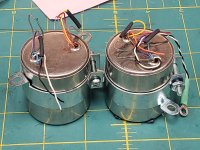
For Sale PAIR Audio Research Jensen JT-346-AX Ribbon Mic Moving Coil Phono Transformers

Jensen JE-346-AX Moving Coil step up transformers. I got these from a retired Audio Research Engineer. he told me these were from a phono preamp design. I am not sure if this made it into production or not. these would have been from the REF phono, or ref 1 phono i believe.I found an ARC datasheet that seems to match up to these but I have no way to test them. If you have a method, please advise and I will be happy to test for you. I also have the jensen PDF's but I cannot post them here. message me and I will be happy to send them to you. there is published info on the web that these are also used as ribbon mic step up transformers.

apparently these are some of the best MC step ups available. and look at the freq response of these bad boys!
JT-346-AX can be wired for either 1:4 or 1:12 step up ratio.

specifications:
Bandwidth -3dB, 1:4: 0.3Hz – 220kHz
Bandwidth -3dB, 1:12: 0.3Hz – 200kHz
Deviation from linear phase, 1:12: +1.0 degrees typical
Noise figure, 1:12: 1.4dB at 5Ohms
Common mode rejection, 1:12: 145dB at 60Hz
Fully balanced primary
Primary may be reversed for polarity inversion
Double magnetic shield

apparently this MC step up is unobtanium now. Jensen only makes JT-347-AX and the frequency band is only half of of the 346 transformers (0.4Hz – 100kHz) and common mode rejection is 20dB (10x) worse than that of the 346 from what i have read. But this info is quite old and may not be very accurate anymore. I have also read that Jensen may still make a 346 but a 346-AXT version


$250 for the pair plus shipping

Please message me with any questions!

Attachments

  • 20240823_181013.jpg
    20240823_181013.jpg
    423.5 KB · Views: 54

MA5332

This is a new class D two channel integrated switch IC from infineon, doesn't seem to be available with distributors yet. Its an improvement over previous IC's like the IR4301. Its particularly exciting for me as it has the following features:
  • 100V breakdown voltage, increased from 80V in IR4301
  • FET rdson typical = 24.4mohm, reduced from 39mohm in IR4301
  • Single supply bridged operation possible using a single IC
  • FET current limit increased from 17A (ir4301) to 40A
  • built in clip comparator!
  • low idle power consumption (only a few 10's mA quiescent)

Datasheet:

MA5332MS - Infineon Technologies

Single supply reference design:
REF_MA5332BTLSPS - Infineon Technologies
I have contacted Infineon to fix the illegible schematic in the manual however they refused, claiming "Unfortunately, this is only what is available at the moment.". Apparently if you register the dev board there are additional documents available however as you can't buy this board yet this may be somewhat difficult.

Simulation BTL implementation:
Infineon Designer powered by TinaCloud

Conventional split supply reference design:
EVAL_AUDAMP25 - Infineon Technologies

Power output in the datasheet is rated upto:
RL= 8ohms, 10%THD+N, Vbus = ± 36.5 V 400 W
My suspicion is that more is possible using a higher supply voltage, better thermal management in the PCB and perhaps an output inductor with a higher saturation current. The inductors listed in the audamp25/ref_ma5332btlsps reference designs saturate around 15A.

Infineon don't make very good datasheets compared to companies like TI. I found the documentation for the IRS2092 useful when working with their integrated ICs as it's the same modulator:
IRS2092SPBF - Infineon Technologies
particularly "IRS2092 and IRS2092S Functional Description".

I also found these app notes useful:
https://www.infineon.com/dgdl/Infin...N.pdf?fileId=5546d46258fc0bc101598b13dd7d2d56
https://www.infineon.com/dgdl/Infin...N.pdf?fileId=5546d462533600a40153559b1bcc115c
https://www.infineon.com/dgdl/an-1164.pdf?fileId=5546d462533600a40153559a9bd31120

Here is a thread on the previous generation IR4301:
IR4301

Neville Thiele Crossover

Has anyone had any experience with the Neville Thiele Crossover, which has notched responses? It is described in the attached US patent (which has expired).
He did a magnificent job of considering phase response and input impedance. His approach can yield a steeper transition than a 4th-order L-R crossover while using the same number of components, at least in the passive versions.
I am considering designing a system using them for my ongoing Klipshorn upgrade project. The KHorn's lower frequency "expiration" point is close to the crossover frequency, so care must be taken not to blow the driver.
I also expect they would have a broad application with direct radiator speakers; I do not know of anyone using them commercially.
Thoughts are appreciated! I think they are worth a look.

Attachments

  • Like
Reactions: MarcelvdG

The Incredible New Technics SP-10R Thread

Stock-photo-SP-10R.jpg

HiFi-World-SP-10R-photo.jpg

SP-10R-lite.jpg

SP-10R-crate.jpg


I know of at least 3 members here who have one. There is a whole new world out there with plinths and modifications just waiting !

Many will know me from the SP-10 thread where I attempt to help people get old ones working. This is getting more difficult (but still possible) over time.

And yes I keep them in stock and sell them.

Click here Technics SP-10R for recent reviews, manuals etc

Here in Europe they come in massive wooden crates with the SL-1000R weighing 85Kkg !

I am hoping a member here "Bon" will tell us of his adventures with plinths later ?

No-global-loop amplification

Hi All,

A Simpelstark amplifier has been prototyped, tested, measured, auditioned.
See the links below:

1) Version 1.1 schematic and PCB views;
2) Spectrum measurements;
3) Assembled board view.

I will most likely try to update the layout, designed by Alex MM, and test it later on.

Cheers,
Valery
_________________________________________________________
Original message - Einbahnstark, etc.

As many times discussed, feedback is inevitable, being present everywhere around us. We also use it every time we design an audio amplifier.
Important point – the way we use it.

No doubt, it’s possible to design a good (or not so good) amplifier with both global NFB loop in place or no global loop at all – in this case, several local NFBs are utilized for controlling important parameters.

After testing / auditioning different designs throughout the recent years, I come to conclusion I like the way the good no-global-loop amplifiers sound. Those amplifiers are well-known in the world of vacuum tubes for decades. However, my focus are solid-state amplifiers and hybrids, designed with series of local feedback (preferably covering a single stage) loops in mind. Damir and other members presented a number of excellent works in this area.

In this thread, I’d like to share my experience in designing an important part of any amplifier – the front-end, providing all the voltage gain – utilizing only local feedback loops.

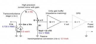
Picture 1 illustrates possible arrangement in principle.
Input stage (transconductance, Gm = 0.5 mA/V) is a heavily degenerated CE circuit – that’s where the most of distortion is born, however at the volume of degeneration used, it’s low enough for the purpose.
Emitter degeneration provides a series-series feedback, providing the desired transconductance ratio and linearizing the transfer function.
2-nd stage is a high-precision cascaded current mirror with current gain of around 2x – highly linear mirroring with a little bit of gain.
Finally – passive transimpedance conversion – resistor load – also very linear, assuming both the output impedance of the current mirror and input impedance of the next stage are high enough.
To satisfy the latter assumption, we have to use a high-quality unity-gain buffer between this resistor and the OPS, as OPS’s input impedance, although it can be rather high, is normally more (especially in case of MOSFET drivers) or less capacitive and rather modulated (especially in case of BJT arrangement).
Small value capacitor provides minimal correction, eliminating possible frequency response artifacts above 1MHz.
It's easy to arrange a balanced input or a fully balanced architecture here - no global loops make it beautiful (just servo needs a bit of redesign).

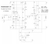
Picture 2 illustrates practical implementation of the above ideas.
The circuit demonstrates pretty good performance – although, I’m presenting simulated results here, I have measured and listened a rather close (a bit less sophisticated) design, showing similar results and sounding just great.

Pictures 3, 4, 5 and 6 illustrate:
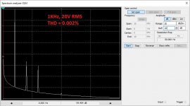
- Spectrum at 1 KHz (20V RMS0;
- Spectrum at 20 KHz (20V RMS);
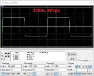
- Square wave response at 20KHz (60Vpp);
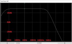
- Frequency response.
Harmonics 2, 3 and very little bit of 5. Looks like a spectrum profile from the vacuum pentode 😊

There may be many different implementations of the stages, including jFETs at the input, folded cascode instead of current mirror, simpler unity gain buffer, etc.

In terms of OPS selection – it must be a low-distortion one. Class A / AB (well-designed CFP, properly biased EF, MOSFET outputs, some error-correction options, non-switching arrangements, etc.).
I used NS-OPS, showing THD < 0.05% open loop throughout the whole audio bandwidth.

What do you think?

Cheers,
Valery

P.S. A simpler no-global-loop headphone amp design is presented here:
Aureaux high-quality no-global-loop headphone amp

Attachments

  • @No-Global-Loop-Amplification.JPG
    @No-Global-Loop-Amplification.JPG
    108.3 KB · Views: 7,228
  • Einbahnstark_2.0-Sch.JPG
    Einbahnstark_2.0-Sch.JPG
    263.9 KB · Views: 7,606
  • Spectrum_1KHz_20V_RMS.JPG
    Spectrum_1KHz_20V_RMS.JPG
    109.1 KB · Views: 6,828
  • Spectrum_20KHz_20V_RMS.JPG
    Spectrum_20KHz_20V_RMS.JPG
    109.4 KB · Views: 6,015
  • Square-wave_20KHz_57Vpp.JPG
    Square-wave_20KHz_57Vpp.JPG
    89.7 KB · Views: 5,937
  • xFrequency-response.JPG
    xFrequency-response.JPG
    90.9 KB · Views: 1,267

Pros and cons: prime MM\MC phonopreamps "X-Altra" & "LP797" vs "Cy-XXI"

The architecture of X-Altra and LP797 MM preamp lightly resembles my PBamp-86 ["Radio Yearbook-86", p. 51 - I am attaching it below], only instead of a bipolar at the input, and the rest an input with a common source, then inverting the op-amp and a common frequency-setting NFB loop from the output of the op-amp to the source of the input transistor, almost like mine. Except for the needlessly stuffed thick capacitor C90 between the input stage and the op-amp.

What's in the negative? Andrew set the LSK389 mode with a drain current of 1.5 mA, and this is 3-4 times less than the current of the optimal mode, in which such fet has the minimal noise [see p. 68 of my book "Technique of high-quality sound reproduction", 1985 , I officially distribute it here https://www.patreon.com/posts/67628599 , and See also Fig.6-16 of JFE2140 datasheet]. We lose a few dB stupidly from scratch, and in addition, by the non-solder R80, to which R79 and R81 are also paralleled, we judge that Andrew does not suspect that the optimal input impedance can be much higher than the "standard" 47 kOhm [ https://patreon.com/posts/70415214 ].

The negative of the circuit design of the input stage is also its high sensitivity to supply voltage ripples. As the author himself notes on page 57 in the third paragraph from the bottom of the left column, PSRR is 0 dB, i.e. the power supply ripples are transmitted to the output of the input stage without attenuation! In order to prevent catastrophic deterioration of the SNR by the power supply, Andrew was forced to build a special active smoothing filter for powering the input stage on the second half of the U26 + R78 + C88 op-amp (at 1000 uF!), and for each channel its own.

I note that in Cy-XXI the two mentioned problems are practically absent due to the fact that in its architecture the first two stages are differential. That is, the noise of the current generator T1 also of course passes to the drains (outputs) of both input transistors FET1.1 FET1.2, but they are common-mode and therefore almost completely compensated as an input common-mode voltage by the second differential pair T2 and T3. For the same reason, interference from the supply voltage buses is also compensated. Those interested can familiarize themselves with the mathematics of processes in detail on pages 71-74 of my book www.patreon.com/posts/67628599 or by googling CMRR, PSRR.

Finishing with X-Altra MM corrector circuitry, let's calculate the number of separating capacitors: C90 + C82 (electrolyte) + C73 + C72 + C61 (electrolyte) = 5 in total, of which 2 are electrolytic. Too many, imho.

Let's move on to MC preamplifier. MC carts are fundamentally different from MM not only by an order of magnitude lower than the nominal EMF (at one kilohertz, typically 0.4 mV versus 5 mV), but also by two orders lower coil resistance (typically 12 Ohm versus 1 kOhm) and by 4 orders lower inductance (typically 75 uH versus 0.5 H). This is actually the lowest impedance and low level audio signal source. Russell for the MC preamplifier applied the recently fashionable complementary pair topology with a common base [ if the sclerosis correctly changes me, proposed at the end of the last century by Marshall Leach, https://leachlegacy.ece.gatech.edu/headamp/ ] on the mystery-covered "magic" bipolar transistors ZTX851/ZTX951.

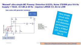
The main design headache in this stage is preventing the ZTX851/951 from flowing significant input mismatch emitter current through the MC cartridge. In contrast to the huge 5000 uF input isolation electrolyte (see Moving coil headamps rev.2, Maxwell version, [ https://hifisonix.com/technical/mc-head-amp-circuit-compendium/ ] ), the floating supply from a 1.5-volt battery (Hawking and Planck) or the unthinkable selection of transistors with a base-emitter voltage difference of no more than 1 mV (Weinberg), Russell originally applied a DC servo on the OpAmp U1, approximately the same as in my Cy-XXI from version 4 and higher. Those, through the resistor R1 monitors the DC at the input and feeds it to the integrator comparator U1, from the output of which through R35R36 controls the base bias Q1Q2 so that the DC input is zero with an error of no more than zero bias voltage U1 OpAmp OPA2188, i.e. +-6 uV. For reference, I used OPA192 in DC servo, which has a +-5 uV offset, but it is better than OPA2188 in the sense that it is made using silent eTrim technology, unlike the 2188 chopper (interrupter), whose modulator / demodulator buzzes at several tens or hundreds of kilohertz, adding sticks to the input currents of the op-amp.

It’s clear with DCservo, but what else is done in Russell’s circuit for a pair of op-amps U3, U4 in each channel? And these are active smoothing filters for the collector circuits of these same ZTX851 / ZTX951. And with a bunch of thick electrolytes C17C18C9C10. And in addition, another 2x1000 microfarads in the separating conduits C11, C16. After all, this circuit is just as helpless against power ripples as the MM part of the Russell corrector, PSRR = 0 dB (second from the bottom paragraph of the left column on page 65 of AXpress February 2021). In terms of the number and capacity of electrolytes, this micropower MC preamplifier with a linear frequency response and a gain of 20 dB bypasses the 100-watt PowAmp on the TDA7294, such a construction is so big that makes it imposisble moutning neither inside tonearm nor even inside turntable.

But for the sake of fairness, we must admit that the scheme of his MC-preamplifier is interesting, because before him no one used DCservo @ input.

But in fairness, it should be noted that the circuitry of the Cy-XXI phonopreamp, with much less complexity and simply drastically smaller dimensions 20х45х3 мм [ https://www.patreon.com/posts/insaidnyi-ot-vip-72574505 ], provides a level 553 nV/root Hz or 75 nV at 20 kHz or 74 dBA with respect to the standard 0.4 mV for a 12 Ohms head. Those almost the same noise as the trendy ZTX851/ZTX951 pair, but without the problems with thick electrolytes and power distillation and easily and trouble-free mounted in the optimal place - in the basement of the conclusions directly to the tonearm inside the turntable.

By the way, the author Dennis Colin, mentioned by Andrew Russell, from whom Andrew borrowed the architecture of the MM phonopreamp, formed his MC phono from the MM phono in the same way that I formed the Su-XXI_v.8_MС from v.7_MM: he simply added 20 dB amplification, and did not bathe with any additional preamps. As a prooflink, see the article by D. Colin from AudioXpress 2007, where on page 3 and Figure 2 you will find that trivial S1A, which is equivalent to replacing the 180 Ohm resistor in the Su-XXI_v.7_MM circuit with an 18 Ohm resistor in Su -XXI_v.8_MC. In conclusion, on page 2 of his article, note how much hassle was with the suppression of excitations of the op-amp. And add that Cy-XXI has 5 times less than "LP 797 Ultra-Low Distortion Phono Preamp". Can someone tell me how to call 5 times smaller than "ultra-small" ? 🙂
Conclusions. Vivat phonocore Cy-XXI 🙂) , no noise, no excitations, no distortion and no electrolytes, right? 🙂

Regards, Nick Sukhov

PS.
More detailed and illustrated info is here:
https://www.patreon.com/posts/pros-and-cons-mm-87586740
https://www.patreon.com/posts/skhema-gerbery-i-86997687

I remind you that in my phonopreamp it is exclusive in relation to the vast majority of others:

-minimum input capacitance 13...25 pF (depending on the version) with an input resistance of 150
kOhm; thanks to this, budget MM heads sound subjectively like top-end MCs.
-the original T-circuit of the frequency-setting negative feedback through R12C4 forms the time
constant tau4 ("7950 us" Amendment No. 4 to 'Processed Disk Records and Reproducing Equipment'
IEC 60098), and R10C3 provides aperiodic RF correction (a kind of "Neumann pole" compensator
"). Due to this, infrasonic interference is effectively suppressed, and the transparency of highfrequency
sounds is also ensured.
For reference: tau1 = 75 us is formed by the R9C3 chain, tau 2 = 318 us - by the R9R12C5 chain, tau3 =
3180 us - by the R11C5 chain.
-active current generator T1, coupled with the first FET1.1 FET1.2 and the second T2 T3 differential
stages provide good noise suppression from the power rails, preventing the need for overthorough
distillation.
-the second differential stage T2 T3 suppresses the fluctuation noise of the current generator T1 as a common mode
signal, minimizing the noise of the input stage.
-along the entire path of the sound signal, there are no electrolytic and generally separating capacitors at all.
-connection of the general feedback circuit to the output stage with a large output impedance ensures the constant
loop gain over the entire audio frequency range and thereby maximizes the overload capacity and minimizes the nonlinear
distortions as in the LF as well as on HF.

The numbering of the elements is according to the Cy-XXI_v.7 circuit and PCB gerbers for MM, from here: [ https://www.patreon.com/posts/skhema-gerbery-i-86997687 ]
Attachments

  • SukhovPBAmp-Radioyearbook86_page51.png
    SukhovPBAmp-Radioyearbook86_page51.png
    331.5 KB · Views: 710
  • cyXXI@ttwithOPA192_jfe2140.jpg
    cyXXI@ttwithOPA192_jfe2140.jpg
    260.4 KB · Views: 703
  • cyXXIinsidemontage.png
    cyXXIinsidemontage.png
    715.4 KB · Views: 582
  • ztxElectrolytes.jpg
    ztxElectrolytes.jpg
    563.6 KB · Views: 669
  • Moving-coil-head-amps-rev-2_Maxwell.jpg
    Moving-coil-head-amps-rev-2_Maxwell.jpg
    234.3 KB · Views: 717
  • AX-Feb2021-ARussellXAltra_page64.jpg
    AX-Feb2021-ARussellXAltra_page64.jpg
    430.3 KB · Views: 767
  • AX-Mar2021-ARussellXAltraP2_page58.jpg
    AX-Mar2021-ARussellXAltraP2_page58.jpg
    343.5 KB · Views: 786
  • Colin LP 797_page_3.jpg
    Colin LP 797_page_3.jpg
    579.1 KB · Views: 785

Another DIY turntable bearing thread

I have read most of the threads on this subject so although no new ground will probably be broken here, here is my start at a DIY bearing methods.

3 pieces I have or I have ordered.
1720814279453.png

0.375 Ream

The drill rod is precision ground, -0.0002 to 0 tolerance.
I will attempt to bore and ream the bronze rod on my 80 year old Southbend lathe.
Will attempt to polish with my hillbilly wet fine grit sandpaper on a foam mandrel. I will try that first before investing in a hone.

This will just determine if I can machine a tight tolerance smooth running bearing in the radial direction.

Do I have any hope of success?

Dbx 290 Reverb problem- noise

Hi everyone.

These days since i have the time, I started repairing again (if possible) this simple DBX 290 (prohect series) reverb unit. I have to admit that i don’t use it anymore so i can risk a bit more.

The problem is that there is a lot of hiss, the more effect is mixed with the signal (when it’s full wet it’s at its loudest).

I replaced the filter caps, but nothing changed.
The direct signal is very good and clean.
The op amps look good (voltage etc).

Could it be something with the converters? Crystal clock?
Which Ic should i focus around? Can i find direct substitutes of such ICs ?
I have to admit that i haven’t got much experience on servicing the digital side of equipment. I usually deal with analog side or power supply problems.

I attach a link to the schematics in order to make things more obvious.

https://jumpshare.com/s/hLJpABpqGydbKFEPb19K

Thanks in advance

Do I need a recone?

I bought these Hemp Acoustics 8” coaxials at a very low price. Is the damage to this cone mostly a cosmetic consideration? These are essentially radian coaxials with a hemp cone. I want to start dialing in the dsp, but I read somewhere that a horn needs to have a smooth surface to work properly.

IMG_1609.jpeg


Would really rather avoid a recone since the cone in this material is not available.

For Sale Parasound Upgrade Kits

I just finished up a Parasound HCA-3500 mod/recap following @bigskyaudio's upgrade list he shared and have some parts left over that I had to purchase in bulk and need to sell.

I am 95% sure these parts also work in the HCA-2200 and possibly other Parasound models.

Here is what I have left over:
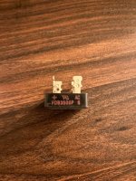
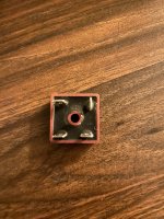
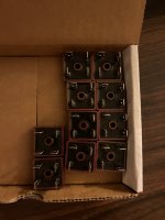
- Diotec Electronics Soft Recovery Bridge Rectifiers (these are VERY hard to get & I had to purchase a bulk amount at $21 each straight from Diotec Electronics)

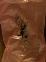
- Holco 47k Resistors (purchased on eBay from West Florida Components for $1.15 each)

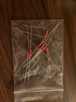
- PR9372 2.2k Resistors (purchased from Parts Connexion for $1.33 each)

I can make 2 kits with the above items and asking price will be $55 per kit. That will include shipping and please CONUS only.

Attachments

  • IMG_2180.jpeg
    IMG_2180.jpeg
    424.3 KB · Views: 65
  • IMG_2182.jpeg
    IMG_2182.jpeg
    449.5 KB · Views: 69
  • IMG_2186.jpeg
    IMG_2186.jpeg
    175.8 KB · Views: 64
  • IMG_2190.jpeg
    IMG_2190.jpeg
    143.8 KB · Views: 63
  • IMG_2185.jpeg
    IMG_2185.jpeg
    233 KB · Views: 63
  • IMG_2189.jpeg
    IMG_2189.jpeg
    241.8 KB · Views: 63
  • IMG_2187.jpeg
    IMG_2187.jpeg
    400.5 KB · Views: 66

Autoranger for soundcards

:cop:

Thread edited to keep chronological order of moved posts.

Introductory note from Jan carried forward from old thread.

Since I started my design for an autoranging attenuator/amplifier I have been posting in other threads sometimes hijacking them. So I asked the mods to collect those posts in a new thread here.

Comments invited.

Jan

---------------------------------------------------------------------------------------------------------------------------------------------------


Hi hochopeper,
If it's a 100 KHz source you need, an LC circuit could make an effective filter to hang after a crude sine wave source. Any of the HP oscillators like the 3336B or 3325A or B would serve quite well. Digital frequency accuracy, digital level stability. The L-C filter network would really do a number on distortion products.

Any of the XR2206 type circuits could also be used with a drop in stability, but still probably better than you need.

-Chris


Hi anatech,


XR2206 looks like the go, thanks! It's times like this that I regret not buying the -S model when I bought my Rigol scope.

Another milestone in the development of the autoranger!
Finalised and tested the cal procedure.
Especially calibrating the freq response for 0.1dB flatness out to 100kHz is a challenge if you don't have a fully equipped lab 😱

I now have a procedure that needs only an AC DMM with reasonable performance and a signal generator that can output 10kHz and 100kHz, preferably up to 10V or more but that's not critical.

The procedure directs you to do some measurements and enter values in a small spreadsheet and the spreadsheet then tells you what to adjust (cap trimmer) for which DMM indication.
For -20dB and -40dB settting, in both SE and BAL mode.

It's done faster than described!

Jan

Jan,

In your note above you mention a source that can provide 10kHz, 100kHz at ~ 10V ideally for calibration. The cheapo XR2206 kits seem to be set for 2V sine wave output. The datasheet has mention of changing a resistor and increase supply voltage to 25V to get more voltage out so no worries there. I don't want this thing to cost any more ($$ or time) than it needs to, should I care about the 2.5% distortion for this purpose? Or should I look for something a bit more sophisticated?


Regards,
Chris

Hi - new member

Hi -

This is my first post to introduce myself so I can make posts. I've been learning electronics (mainly audio gear) and signed up here because I'm looking for a schematic for a Peavey Max 110 Bass amp that I'm trying to repair. I've found the problem but need the schematic so I can implement the fix properly. I'm not really expecting an answer here in the New Member / Introduction section (that would be great though) and plan on posting in the Schematics section but have to get through this intro first before I'm allowed to post. I don't like to waste people's time with repeated questions so believe me, I've searched high and low on the internet and while there are a lot of Peavey schematics out there, this one is elusive.

Best regards,

Adam

Krell KSA-300S Repair

I've had my Krell KSA300S in storage for several years (climate controlled) and recently removed it to set it up in my house. The right channel didn't come up no lights, nothing. The left channel appears ok. No smoking gun either. So I started the journey to see what is going on.
First the visual check showed nothing obvious and no smell of a dead part. Capacitors look fine (haven't actually check them) but visually fine. To start with I check the voltage going to the output board and on the right side zero or a few millivolts. the left side wash according to the spec (73v).
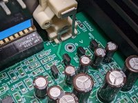
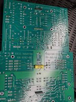
So, I took the right side apart first thinking that the bridge rectifier could be at fault. Have yet to check it or the caps associated with it, because I did notice something weird. The 6 pin connector (there's 2) one of them had the middle 2 pins missing. Noting the fragile nature of the connectors I was careful separating the driver board from the output board. There were no pins anywhere and I'm very sure I didn't break the 2 since they would still be in the connector if I did. This unit worked fine before storage, so I'm trying to find out if those 2 middle pins were purposely eliminated at the factory. The photo shows the (upper portion of board the 6 pin connector with the 2 missing. The second attachment shows where I was measuring 0 volts.
Any help would be appreciated.
Thanks,
John

Attachments

  • IMG_1451.jpg
    IMG_1451.jpg
    752.8 KB · Views: 141
  • image45791.png
    image45791.png
    52.7 KB · Views: 136

Relationships between Qtc, F3, Fb in acoustic suspension enclosure

Let’s focus on a sealed enclosure system, there are engineering terms involving Qtc, F3, and Fb.

Firstly, I’m not sure whether I can call ‘Fb’ as “the tuning frequency of the box” because I used to be told that the closed box has NO tuning frequency. He suggested me to call it as the “box resonance” instead of the previous word. So, I’d like to hear opinions whether his statement is true. Can I call ‘Fb’ as the tuning frequency (of the closed box)?

Secondly, if we consider Qtc of a conventional system, it would be recognized as Qtc of 0.707. And it will give F3 at the same frequency as Fb (F3 = Fb). To my understanding if Qtc is lowered than 0.707, the result will become F3 > Fb, and vice versa for the opposite case (Qtc > 0.707 ==> F3 < Fb). Does my understanding correct?

Finally, assume we have a closed box system that is specified as F3 = 28Hz and Fb = 36Hz. It’s clearly seen that this system will be categorized as Qtc > 0.707 (underdamped). But, if the F3 occurs at approximately 50Hz, it becomes an over-damped instead (Qtc < 0.707). So, does it mean the underdamped characteristic will be better choice since it produces lower F3. IOW, it provides deeper bass output. Is my assumption correct? However, this assumption is based on the fixed Fb (@ 36Hz). I’m not sure if it will be available in the real world. And if it doesn’t appear, how does the Fb behave regarding the F3?

Tube preamp with balanced outputs (cfa+vfa)

This is the second version of my tube preamp but this time has different goal, not to drive headphones but I wanted balanced outputs to drive power amp directly so everything is optimised to drive line-level loads.

Compared to the first version I have significantly upgraded power supply. High voltage part contains CRCRC filter before it goes to the mosfet + LD1086 regulator with lots of blocking and capacities around. Thanks to this I have basically battery-like psu for the tubes with excellent mains filtering.
For tube filaments I have LM337/317 balanced psu with again lots of filtering around and slow turn-on.
There is also regulated 5V1 psu for relays and controll of the preamp + to power raspberry pi board with DAC ES9038Q hat for wifi audio streaming.

Audio path / voodoo improvements over 1st version:

  • in signal path there is minimum coupling capacitors and if so all are audio-grade polypropylenes
  • I wanted to minimise series relay connection as much as possible, so there is only one reed-relay at the input selection, for the output mute I choosed relay to short to the ground so there is no signal going thru the contact.
  • All impedances are lower also in feedback loop
  • I have improved current sinks in input differential pair = TL431 + low noise BC550, soldered from the back of the pcb to even smaller thermal drift and improved stability

There is my own "invention/evolution" design of combined voltage and current feedback directly into input differential pair. Thanks to this, preamp has excellent stability, transient response and low distortion. Thats why its somehow VFA/CFA preamp, I have tried this in previous samples also with WCF output (white cathode follower) for unbalanced version with even better results of 0,0002% THD into 300R load 😎

Audio extras

- audio part of PCB is standalone so its possible to wire it via IDC ribbon cable to whatever control board, I have designed two versions:
Analog "pure" one with 555+4060+4040 timers
Digital with attiny with IR remote control
  • there is automatic power-off function after 30minutes without audio signal to save electricity and tube life.
  • stereo/mono switch
  • preamp gain switch
  • (tape)monitor switch
  • hardware mute switch
  • as mentioned in psu section above, one of the inputs is RPI with DAC hat for dlna audio streaming thru wifi
  • first line input contains also remote-out +5V trigger so its possible to turn on phono preamp with selecting the one

Preamp schematic:

preabal1.png

PSU

preabal2.png

I/O

preabal3.png

Control
("analog" without remote) // edit // actually I noticed one change in schematic, that I have not used T2, as that would send (audiodetect) reset loop all over the place from analog to digital gnd, so I have replaced this one with cny17f opto to have this competely clean and separated. Digi gnd is complately isolated from analog gnd, and only one way where they meet is from DAC RPI hat into analog input. By doing so there is absolutely pure connection without any mess in harmonics...

compsimpsch.png

Some build pics

IMG-7656.jpgIMG-7677.jpgIMG-7678.jpgIMG-7679.jpgIMG-7682.jpgIMG-8078.jpgIMG-8157.jpgIMG-8158.jpg
IMG-7675.jpg

Mechanical design

I wanted to design future-proof sturdy enclosure with complete access to PCB from both sides... The main structure consists of separated rear panel (for easier label printing), 8mm thick machined anodised aluminium front panel, and to interconnect panels there is C-shaped profile on side which creates base for PCB and on other side U-shaped tunnel with the very same function but to also hold transformer and to cover all the wiring inside of it:

IMG-7753.jpgIMG-7749.jpgIMG-7756.jpgIMG-8155.jpg

For absolute best mains filtering I have used custom audio-grade toroidal transformer with earthed primary/secondary copper shielding. Transformer windings are shielded on the outside by several layers of laminations. I potted whole assembly into iron cover with polyuretane potting compound. So as a result transformer is tripple shielded. Toroidal iron cover is actually hanging in the U-shaped tunnel by rubber vibration dempeners, so its also mechanically isolated from the rest of the chassis and "levitating".

IMG-7703.jpgIMG-7710.jpgIMG-7720.jpg


Aand as upload sucks and cannot insert more images and when i do so on external server i get hated i will continue in next post🤔

Lame advertisments

I swear, advertising has gotten more and more idiotic and lame these days...
Does anyone remember those TV commercials for State Farm Insurance from a few years ago?
Specifically, the "Hi, I'm JAKE from State Farm!"
Seems ole Jake is a drifter... must have lost his job at State Farm for telling people he wore Khaki pants.

Late last year, I started getting robo-calls from him...but his new line of work was....credit cards.
"Hi, I'm Jake from Discover!"
And this past week... "Hi, I'm Jake from Visa-MasterCard!"

Poor soul can't stick to one company for long.
And no, I don't bother to ask what he's wearing.... I hang up.

Can someone verify my Output Transformer calculations?

The methodology is from http://www.geofex.com/Article_Folders/xformer_des/xformer.htm

Winding a OT for a Vox AC30.

Power = 30W
Primary Impedance : 3700 Ohm / 4kOhm (depending on the source you use. I went with 3700)
Secondary Impedances : 4/8/16 Ohm
Lowest Frequency= 70Hz
Highest Frequency= 12Khz
Bobbin Area = 3.75 square inches

Using equation Primary Turns = (Vrms x 108)/(KfbA)
where

V= voltage swing in RMS
K= 4 dependent on stacking factor
F= lowest frequency
b = maximum flux density (went with 14KG)
A = Area of stacked tongues (bobbin area)

To find V in this source it shows the AC30 has a voltage swing of 295V peak to peak although the wording is a bit unclear. Converting to RMS we get ~ 105Vrms.

Applying in the above equation I get 714.2857 turns .

HOWEVER in this source at the very end it states that Vrms is 1.1xB+ , which in this case is 345. giving a value of 380Vrms for the input. This is quite a dilemma. I'm unsure about which value to use as comparatively my value for turns is very low compared to a document I found about winding a AC30 transformer , albeit their core was smaller. Please help me get over the last piece of this puzzle ! Thank you all so much.

JLH10W- MOSFET output

Hi all
There seems to have been some attempts to use MOSFETs in a JLH69 original.
Here is another. Some comments -
not exhaustively simulated, nor experimentally tried out yet.
distortion seems pretty good (for simulation) at .02% at 20kHz and .007% at 1kHz.
Resistors R8 and R9 are very likely going to have to be variables (one or both) to adjust for Vt differences.
Concept is to use a fairly powerful FET (high current anyway) so that it operates in a linear region at a quiescent current of about 2A (depending on required output power etc. )
As with my earlier differentially driven 16W design, the voltage drive is split using equal load resistors R7, R10 which is about the only way to drive the FETs in equal and opposite directions.
Source resistors used to limit the current, otherwise I have kept this to 4 transistors as per the original.

Attachments

  • JLH 10W MOSFET.png
    JLH 10W MOSFET.png
    11.1 KB · Views: 782

WTB Minidsp 2x4 HD

I am looking for a used minidsp 2x4 HD as I wanted to try a open baffle that I acquired few Eminence Alpha 15A woofers with my existing Fane full rangers. Not a big fan of DSP and prefer a passive crossover but a minidsp seems to be a good solution in the interim to check different options before finalizing the actual crossover.

Please ping me with any offers local US and if interested I do have some spare power amps, dac to swap instead of cash or just cash.

Thanks

Schnuckelchen | T25A-6 | Mid120_vHE | WO24P-4 | FA503

EDIT: Moved from "System pictures & description" thread as discussion arised.


Hello everyone,

i may introduce my latest speaker to you:

Name: "Schnuckelchen" (= german for sweetheart, darling...)
Hi: Bliesma T25A-6
Mid: Kartesian Mid120_vHE
Lo: SB Satori WO24P-4 @ 24l CB
Amps/DSP: Hypex FA503

schn1.jpg
fertig_1.jpg

mess2.jpg

bau7.jpg


Drivers integrated in enclosure driven by FA503 +/- 90° hor and ver, measurement distance 1,5m, calibrated mic, 0° responses of woofer and midrange merged with nearfield response + enclosure simulation:

SchnuckTreiberEinzeln.PNG


Resulting xover / filtering, optimized for +/-60° hor +/-40° ver power response:

SchnuckSystem.PNG


Best regards
Peter

A second try to build a 2-way speaker

Hello, I am new to this forum and also quite new to try to build loudspeakers, no expert that is. I wonder if someone could give me some input on a 2 way crossover that I try to designe with the help of VituixCAD2. The speaker elements are Monacor SPH-165KEP and Scanspeak d2010-851300 tweeter. The box is 18 liter basreflex. I shall try Monacor recomendations for size of tube. I read a lot in the The Cross Over Design Cookbook, so therefore this is what I came up with. The impedance seems a bit low? I had to plot all curves for these elements since I could not find anything online. Also the SPL curve is a bit up and down. Any input regarding this would be nice, if possible. Thanks

Attachments

  • Like
Reactions: knotscott

electronic miscellaneous

Hello everyone, I have a lot of new electronic material and I would like to offer it at a good price for the forum (all original material not Chinese), I can put some examples of components, but I don't have referenced everything I have, so you can consult by private, greetings.
2N3583 - NPN transistor, 175V 1eu.
SC 108 0.10eu.
BC 308A 1 eu. 100u.
2N3054 0.5 eu.
BC183C 1eu. 100u.
BC183b 1eu. 100u.
BU105 1eu.
2n6073a 1eu. 10u.
BC516 1eu. 100u.
2n6043 2eu. 4 u.
BD238 1eu. 10u
2N6073 5eu. 50u.
Wima MKS4 100v 100nf 2eu. 10u.
BU508Dw 4eu. 5u.
LM393M 1eu.5 u.
MKP 1uf 250 Faco 1eu. 4u.
Diode RS505 80 1eu. 6u.

and more than a hundred other references.
  • Like
Reactions: Roppu

The new one... Again

Hello,

like most people here, I would like to introduce myself so that I can fully use the functions of the forum.
Well, let's go. I've been passionate about good hi-fi for a good ten years and came across Nelson Pass very early on. Since then, I've been diligently replacing parts of my Sony ES system with his components and I'm more and more excited each time about what he is teaching us nexted. A very big thank you at this point. Without you, I probably would never have dived so deeply into this topic.

Hello and greetings, my name is Sojourn

New guy. Hello and greetings my name is Sojourn and use to be be with diyAudio a ways back. And now back again in this wonderful forum! I have been away from diyAudio for some time as traveling and new chapters in my life. However, I am working on diy projects again after quite a few years. Krell KSA 50 and Alex Cavalli's Bijou headphone amp. I have quite a few items I will be posting in for sale from my parts I collected quite a few years back that you may be interested in. Best regards, Sojourn.

Sony STR-6065 with low FM volume

Wondering if anyone can help guide me on something as tuners are admittedly my biggest weakness when restoring vintage audio.

I have a Sony STR-6065 that was dead with 1 channel completely toast; rebuilt the power supply and power amp board, new filter caps, new outputs... everything works and sounds great, except FM. When in FM mode, at first it was doing nothing. No sound, nothing. I threw new caps in the MPX board since it was already open and now I am hearing something, and it's tuning and pulling stations, but only at a fraction of the volume of everything else. I pulled the IF board and started re-working that, but something keeps pushing me back to the MPX board.

In the schematic it looks like the MPX board goes direct out to the power amplifier. I'm still trying to get my head around the block diagram (again, tuners are a weakness). Would it be most likely if I'm getting any type of volume drop before it hits the amp section, it would be in that board?

I also just noticed that there are a few tantalum caps in the MPX that I didn't change and should pull.

AER compact 60 amplifier chip

Hi all,
I have an aer compact 60 that stopped working mid-gig. The TDA7294 had blown, thinking that was the issue we replaced it and it blew again. After measuring voltages we're measuring 73 volts to the TDA7294, considerably out of tolerance for the amp chip. We replaced both 35 volt 4700 uf capacitors but voltage is still measuring 73V. The unrectified voltages are 27 volts on each side, any ideas what might be happening?

Pulsar Clock - Ultra Low Noise OCXO

In the context of the continuous research that involves many audiophiles and technicians in the improving of the listening experience we concentrated to the central role of the oscillator in the digital to analog conversion process.
The analyses led to the implementation of the Pulsar Clock, an ultra low phase noise oscillator capable to assure significant improvement of the sound quality reconstructed by the Digital to Analogue Converters.
The Pulsar Clock is a low power consumption oscillator compatible with the standard DIL14 clock pin layout, it requires 50 mA only for regular operation and just 150 mA during the brief warm-up phase at 3.3 Vcc.

Pulsar Clock is a so extreme oscillator to be classified as a "Dual Use" device whose distribution is ruled by severe international regulations.
For this reason we are authorized by the European Union Authority to distribute the Pulsar Clock in a limited number of countries:
Australia, Austria, Belgium, Bulgaria, Canada, Croatia, Cyprus, Czech Republic, Denmark, Estonia, Finland, France, Germany, Greece, Hungary, Ireland, Italy, Japan, Latvia, Liechtenstein, Lithuania, Luxembourg, Malta, Netherlands, New Zeland, Norway, Poland, Portugal, Romania, Slovakia, Slovenia, Spain, Sweden, Swiss, United Kingdom, Unites States of America.

For those who are not in the above countries and are anyway interested to the Pulsar Clock a specific quotation request page is available to collect your wish, but a quotation will be provided only after and if a specific export authorization will be released by the relevant authority.

For the above authorized destinations a first batch of Pulsar Clock is now available and it is possible to request a quotation for the following frequencies (specified in MHz):
11.289600, 12.288000, 22.579200, 24.576000, 45.158400, 49.152000, 90.316800, 98.304000, 100.000000

The Datasheet and the Quotation Procedure are available at the following link:

https://drive.google.com/file/d/0B4JU1DLmHzHsTXNKVWN0UzlvQW8
.

4-800 Hz wiggle i my 3 way diy

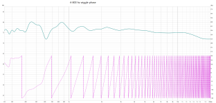
Playing around with mesaurements on my latest 3 way diy before i will do the last finetuning, and the wiggle bothers me.
Do you experienced people have some ideas about getting i better?

Mesaurement artifacts?

the mic is 120 cm away center midrange.
A SS 18M4631T00 doing 150-2,4 K in 4 liter box.

Regards John

Attachments

  • 4-800 hz wiggle.png
    4-800 hz wiggle.png
    19.1 KB · Views: 225
  • 4-800 hz wiggle phase.png
    4-800 hz wiggle phase.png
    105.9 KB · Views: 229

Help Identifying

i am trying to find out more about these monoblock tube amps. i picked them up used with no information. They each have 4 el84 output tubes, can't remember what type of input tubes. They really sound great to my untrained ear. Any help identifying what these are would be greatly appreciated. Are these from a kit or a custom build?

Thanks,
Robby

Attachments

  • PXL_20221209_184310841-EDIT.jpg
    PXL_20221209_184310841-EDIT.jpg
    574.7 KB · Views: 130

SMSL Sanskrit 10-th MK-III > No output anymore

Hello gents,

Some advice needed. I'm running a rpi-4 with bubble-pnp server with a Qobuz subscription. The rpi is connected with usb to my DAC. The RCA outputs from the DAC feed directly into my Wolverine amp with KEF reference model 3's as speakers.
Sofar for the setup which has worked for the last 2 years or so.
Yesterday I bought a new TV and I used the optical out from the TV to the DAC. This didn't work but the really strange thing is that the DAC now doesn't produce anything anymore. Also not without the TV.
The DAC still recognises the rpi-4 and when I start a song the DAC displays the freqency (ie: 44khz, 96khz...etc....)...but no sound. I've changed the amp to make sure the amp is still working. Thank god the amp was fine. Changed the DAC to my older smsl sanskrit 10-th MK-II and the old DAC did work.
So my conclusion is I broke something the moment I connected the new TV with optical-out to the MK-III. I find that hard to believe to be honest but.......

Considering the fact the DAC still recognises the rpi-4, i guess the RCA outputs are broke somehow.

Can I fix this? I'm a good solderer (ie: built the wolverine) but I don't know how to test components IN the DAC or what I'm looking for. I don't see blown caps, smoek or black traces anywere on the PCB.

Another option is offcourse to replace the DAC in a price range of around € 200,-...any tips welcome

reg

willem

DIY Front End 2022 - switched gain?

About to ask a question which will show my ignorance of field interference...

My understanding on gain being the ratio of r3/r1 would it be possible to replace r3/r4 with a small switched resistor circuit, so as to provide for two different gains? or maybe three...

I understand the resistance part of it, but I am wondering if this would introduce some weird em field that I would never understand...My plan would be to have the resistors up off the front panel switch, separate from the circuit board.

Thanks!

Compact SMPS filter using AmyAlice circuit design

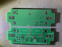
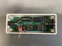
Here's a compact SMPS filter using the AmyAlice circuit. It includes an optional switch circuit to kill the power and prevent "preamp turn on thump" when used with the ACA mini. Unfortunately, I don't have the test equipment to see if my layout performs equal to the MJ PCB but it sounds good to me! Feel free to use the attached gerbers and BOM as you see fit.

Assembly notes: I used the manufacturer's footprint for the inductors and I find the pads are almost entirely hidden under the device. As a work around, I was able to solder one side and then slide it over a wee bit under heat to do the other side. Also, the double sided foam tape under the PCB did not have the protective strips removed as I only used it to provide some backing tension for the #2 PCB mounting screws. If you don't use the screws, you can use it as mounting tape. Getting the enclosure holes located exactly right is the hardest part. The input/output DC jacks can be slid fairly close to the insides of the box. I recommend tacking them to the PCB using only the + terminal and double checking the fit and adjusting as necessary before final soldering.

R1 update notes:
Change D1 P/N to 576-P6SMB68A
enlarge L1 and L2 footprint solder pads to facilitate easier soldering

Attachments

ali express super cheap amp - is it possible its 12wpc is 8ohms

ali express super cheap amp - is it possible its 12wpc is 8ohms


-https://www.aliexpress.com/item/1005006746074265.html?spm=a2g0o.detail.pcDetailBottomMoreOtherSeller.94.2ee55DGe5DGeH7&gps-id=pcDetailBottomMoreOtherSeller&scm=1007.40196.394786.0&scm_id=1007.40196.394786.0&scm-url=1007.40196.394786.0&pvid=70cac017-3398-42ef-b6a7-07ee3efdbcba&_t=gps-id😛cDetailBottomMoreOtherSeller,scm-url:1007.40196.394786.0,pvid:70cac017-3398-42ef-b6a7-07ee3efdbcba,tpp_buckets:668%232846%238111%231996&pdp_npi=4%40dis%21GBP%21196.38%2198.19%21%21%211795.06%21897.53%21%4021039c5917249515732538655e0268%2112000038168444962%21rec%21UK%21863394078%21ABX&utparam-url=scene%3ApcDetailBottomMoreOtherSeller%7Cquery_from%3A

Measuring Loop Gain on the Bench - Best Way?

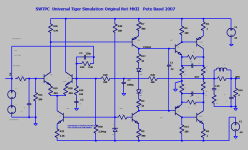
I'm looking for the best, simple, way to do this on the bench without more than
a function generator (my HP goes to 11 MHz) and a scope. Our scope has a
readout of the signal amplitude and is 200 MHz. This amp is a prototype so soldering
minor changes is not a problem.

I used LTSpice to draw what I'm planning to do on the bench to measure the loop gain
of the original Universal Tiger (UT) amp. This is NOT the way to do it in simulation but
of course it will run. The best way in simulation is to use a Tian probe as explained in
these videos by one of our members:
https://www.diyaudio.com/community/...al-tiger-inconsistencies.365751/#post-7737499
Let me say that I understand that this method introduces errors but from what I
see/understand I don't think that they are significant and I welcome comments to
improve it or use another method.

The main feedback path is broken at the output and the SPICE ideal signal source drives
it. The obvious errors are that the loading on the output by the feedback network
is removed (more parts could be added to emulate it) but since the load is 4-8 ohms I
believe that the error is insignificant. The other error is that the source impedance of
the amp output is not accounted for. Now amps like this are (should be) high damping
factor and therefore the output impedance is low in the audio band. The zobel is in
parallel and should keep the impedance low at high frequencies. The circuit needs a
stable DC output and therefore a feedback network matching the pos input resistance
to ground is added with two resistors (R29, R28) and a large cap to ground to shunt
the signal. This introduces error below 1 KHz but that is not where the analysis takes
place. There was significant DC offset at the output, as is seen in real hardware, and
a very large resistor, R30, was added to trim the offset. This is not how to do it in real
hardware but with an ideal power supply in sim it works fine.

The output to measure is the point where the loop is broken with the OUT label, not
the SPK labeled net. Plotting frequency response in LTSpice is OUT/Vin from the source
which is what we want. Anyway, here's the diagram:
TIGER LOOP GAIN BENCH.PNG

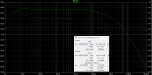
Ran it to see if the results are reasonable and what to expect on the bench:
It shows an unstable amp, but perhaps I'm missing something, we do know that these
amps certainly do oscillate in real hardware.

Odd that LTSpice does not make the two cursors different colors in the plot.

==== PHASE MARGIN
Cursor 1, furthest to the right, is at the 0dB gain point (the horizontal cursor is at 0dB)
where we should look for phase margin on the phase plot (the vertical cursor). Note
that we are driving the negative input and therefore, in the passband, we see -180 deg
as would be expected on the inverting input. The point where there is zero phase margin
is another -180 for a total of -360 bringing the signal back in phase to cause oscillation.
The amount less than -360 is the phase margin.
Note that for cursor 1 the phase is greater than -360 at about -390 and according to
this there is about -30 deg of phase margin - there is none. Keep in mind that this is
device and model dependent so real hardware could be better or worse.
Or is this not a valid method?

==== GAIN MARGIN
Cursor 2, on the left, is where the phase reaches -360 deg (vertical) and the gain
margin is how much less than 0dB the gain curve shows. The gain is actually greater
than 0dB and therefore there's negative gain margin with it showing 12.47 dB of gain
(horizontal) - it should be negative in order to have gain margin.

It should have been obvious that the stability of this amp is highly dependent on the
process variation of the semiconductors which is demonstrated by the fact that I have
one amp that readily oscillates and another of the same revision that does not.

TIGER LOOP GAIN BENCH FIG.PNG
Projects by fanatics, for fanatics
Get answers and advice for everyone wanting to learn the art of audio.
Join the Community
507,530
Members
7,875,778
Messages

Filter

Forum Statistics

Threads
405,668
Messages
7,875,778
Members
507,530
Latest member
T_Sharp