Dear friends
God bless you all.
I have a pair of focal audiom 13wx and pair of audiom 15wx
I need an help regarding to make a clone of the wilson audio alexandria xlf
If there is anyone in this group who has a friend with the real wilson and can supply measurements of the bass enclosure and the port measurements.
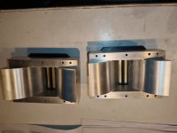
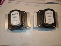
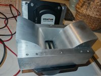
Selling my Visaton MHT-12 magnetostat tweeter pair. They are from year 2021, I have bought them used 2 years ago. I have used them in a two different speaker projects. I have also CNC machined custom waveguides. With these waveguides they can be mounted to a square front panel hole, mounting hole size 146mm x 65mm. Waveguide depth is 65mm. Included is also 3d printed adapters to perfectly match tweeter flange to waveguide opening.
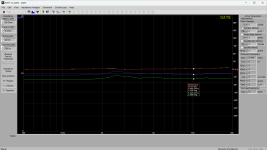
Attached is the DATS measurements, they show a slight (~0.5 Ohm) difference in impedance throughout the range. Also one of the tweeters has a slightly wrinkled diaphragm, hard to capture on photos. Anyhow, they worked both normally on both of my project speakers and showed similar frequency response (could not find the measurements from anywhere anymore though).
The price of 2 tweeters, 2 waveguides and adapters is total 300€ + shipping from Finland. This is the price what I paid for the waveguides only.
I have a CEC TL2 transport. it plays music for a short while then after that the sound is garbled/garbage. I had 2 technicians to look and try and repair but doesn't work.
Any suggestions on what I can do with the spoilt TL2? possible to replace the circuit board or something ? or should i try to sell it ?
I have been discussing this new product for some time now during its development stages in the What’s On the Bench Thread. But I think it is time for its own dedicated thread. This usually happens when we reach a point of critical discovery or progress. Today is that point. We have conclusive data showing that a parallel plug-in filter (not a flow through filter) can reduce SMPS noise that contaminates AC mains power lines and outlets strips. The SnubWay Noise Defender is a compact module with a 120vac NEMA plug for the U.S. and Euro compatible Schuko plug for the 230VAC EU market. The 230VAC version remains to be tested.
I initially showed that the SnubWay can filter out 60kHz to 400kHz signal from a function generator imposed on an outlet strip. This was not plugged into a wall outlet or any real equipment.
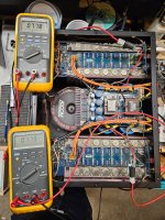
Recently, I have made tests using a spectrum analyzer to look at the noise floor of the audio output of real devices to see if the noise floor can be improved by plugging in the SnubWay. I had a small SE Class A headphone amp (LuFo Lite) repaired and so I thought why not look at its noise floor. I was pleased to see that there was some 3kHz to 5kHz “grass” on the noise floor that was subsequently cut down by the SnubWay.
Above is a photo of the test in progress. You will notice the funny lampshade on the LuFo Lite (needed to cover the bright halogen bulb acting as resistive loads in the signal path). Here is the closeup of the noise floor cleanup:
Here is a photo of the MC phono line stage (Jhofland’s interpretation of a Pearl 3). It has a separate linear PSU connected by an umbilical to keep the noise low.
Here is a photo of the bench setup used to measure the phono line stage:
The noise floor of a phono line stage is one of the most critical low noise audio devices that we use in our systems. Given that the gain in these systems is around 60dB (that’s 1000 x) any sort of noise can be amplified and heard. Which is why it’s important to have as clean of a power source and power supply as possible for MC phono stages. Here is the measurement of the impact of the SnubWay for the output of the phono line stage:
Here are technical details of the testing:
Spectra were acquired using 256k length data sets acquired at 192kHz and FFTs processed with Blackman Harris 7 window function with 16 averages. Focusrite 2i4 USB audio interface and REW software. 100kHz 8th order passive brick wall filter on FFT input to prevent data aliasing from high frequency content. FFT scale: 0dB FS is 2.2vrms.
And here is what it looks like to use the SnubWay - simply plug it into the power strip:
Here is what it looks like inside:
It is a parallel network of 5 LRC filters designed using LTSpice circuit analysis and laid out on a stack of 3 two sided PCBs using premium SMT devices such as carbon film high energy pulse resistors, X2 rated safety film caps and CoilCraft shielded inductors. There is also an MOV/GDI for lightning suppression and protection from high voltage transients.
The 3D printed prototype looks like this:
The final product will be in satin anodized CNC’d aluminum with a premium Viborg acrylic base and copper wall outlet pins/blades.
We are now working on CAD models to produce the SnubWay that will look something like this:
We are still debating on final finish and color choice.
Here was an early test of the prototype as a P2P circuit and tested with a function generator noise source. Login to view embedded media
My name is Anthony Chandler. I am an English and Design Technology teacher, and my father was an electronics technician of 35 years before his death a while back. I am excited to improve my soldering skills and figuring out how circuits work. That being said, I am no expert. I have built a Bottlehead Crack, started the ACA Mini, and now have finished the ACA v.1.8, but have problems with Channel A; probably a good time to join the forum and ask for advice.
I read the posts all of the time, but I have not needed to post before. Some day I hope to build a phono preamp of some kind and whatever else comes my way.
Last week I bought a 5800 amp. During the demo in the seller's home the unit sounded good and I had no suspicions so I paid him and lugged it home.
I had read that bias & offset can be an issue with these so my test bench was it's first stop.
I noticed an oscillation on only the positive-going half of each sinewave, but only when turned up to 10 watts or more.
The amp is capable of full output from both channels, but the oscillation makes my load resistors whine.
What would cause this audible ringing at high output, only on the positive half of the signal?
The rail voltages were right on spec.
Bias & offset were adjusted to spec after a LONG heat soak. I can verify what others have written that this amp drifts until it's good & hot.
The fan speed is proportional to the temperature, and bias is very sensitive to temp. It's a delicate balancing act.
The free National Audio Book chapter 2.4 has schematics and component selection procedures for passive and active audio tone controls. I would like to automate the procedures so there is error checking and minimal tedious keyboard work. But the National examples do not report the results for 3db calculations.
The bass-treble example in LM4562 spec prints:-
// These are the different values for example in the LM4562 spec
// fL ≈ 32 Hz, fLB ≈ 320 Hz
// fH ≈ 11 kHz, fHB ≈ 1.1 kHz
But my script prints:-
// 31.83, 289.37, 8841.94, 869.70
// Minimum treble R4 pot 292000.0
So they diverge too much for treble values. I verified my calculations with the Digikey 3db filter app ... ok
It does not matter if these maths are done with 4-byte floats or 8-byte double precision. I wrote a small C program for testing. Most software languages depend upon standard C/C++ libraries so results should be consistent across applications.
Since the National Handbook is dated 1976, the math was probably done on an ancient minicomputer with unknown software quality.
Another concern is the high value pots, 100k to 500k, used for these controls. Would they be noisy for audio circuits?
In my search for a discrete phono-stage I fell over this old schematic on Paul Kemble's webpage.
It seems to originate from Wireless World, I wonder if anyone has built this one? The original is for dual 25V supply but I assume it will work for single supply too as shown on the second image.
There is no global feedback and bias is controlled by the voltage drop over 2 and 5 diodes respectively. A strange arrangement that needs to be modeled in spice and tested by experiment. The RIAA equalizer is of a passive type across the collector resistance of the first transistor.
If this works it may be an alternative to the Pacific-style jfet phono preamps, since it is based on standard bipolar transistors and not on difficult-to-obtain 2sk170's.
Instead of one open baffle 18" or 21" bass driver I am investgating the possibility of 16 10" drivers in Ripole configuration.
What can I expect sensitivity wise? In theory if the drivers are wired to a 8ohm load the sensitivity will go up by 12db right? So if the drivers are 90db sensitive combined they are 102db sensitive. But I read somewhere it might be a bit less due to losses which seems reasonable. Otherwise you could build an infinitely sensitive array and blow up an entire city.
So let's say the sensitivity ends up being 99db. That means the same amp plays 9db louder with 1w@1m
But instead of one speaker rated at let's say 100w now I have 16 drivers. So intuitively I would think if I needed a 100w amp for one driver I would want a 1600w amp for 16 drivers.
I guess I want a higher wattage amp for 16 drivers but probably not 16x.
I don't know much about electronics so please be gentle with your explanations.
High is good but I want to make it better.
Is it possible to do it without measurements.
If yes, Any kind soul would look at the design and frequency response and suggest what tweeter can I replace it with. Has to be same size and metal face plate.
Simulating speaker response gives me great joy and my personal 'challenge' is to be able to achieve the same as software like WinISD and Hornresp. I use Matlab for generating the plots, and if the acoustic part cannot be represented by lumped elements I use ANSYS Mechanical to generate the acoustic impedance by applying a velocity to the diaphragm and export the average pressure over the diaphragm. The complete circuit is solved for all frequencies in Matlab, by applying the 2-port network approach, which I got from Leo. L. Beranek & Tim J. Mellow's "Acoustics".
All of the above is fine, but there is a more complex problem, for which I am looking for some help (or motivation 🙂). 2 loudspeaker diaphragms enter a horn, where they are not loaded equally. My current workflow cannot deal with this. Below is a fictional example.
Summary:
- 1 speaker diagram, see below. This Matlab Simulink model is not used for calculation, only to show how my 2-port network Matlab script works. This is solved fine, and if required the acoustic impedance from ANSYS Mechanical is used for Zafront and/or Zarear.
- 2 speaker diagram (wired parallel), see below. The electrical and mechanical parts are put in subsystems for readability.
And a generic design in which these speakers are located, see below. 2 10" speakers, where both diaphragms have a velocity of 1mm/s. The 2nd speaker has a round obstruction in its way. The model is 1/2 symmetry. All boundaries are rigid, only the sphere's surface has absorption elements on it to allow wave propagation outside the mesh domain.
At 10hz the obstruction does not really affect the pressure on both diaphragms (or at least equal to both):
At higher frequencies we see the diaphragms are loaded differently (219Hz):
My parallel speaker diagram is probably not correct, because both diaphragms are affecting each other, so there must be a link between them somewhere. Beranek's book shows an impedance matrix which (I think) can be used to solve this problem. It needs 4 elements (z11, z12, z21, z22) which describe the relation between the pressure at both diaghrams, as functions of both velocities of the diaphragms.
Maybe some acoustical or mathematical wizards can help me solve this, maybe by elaborating on the impedance matrix for example. In the meantime I will try to do my homework by solving it myself 🙂.
Hello everyone!
I'm Tasos of EposLab , my lab is located to West Peloponnese , Greece!
I run various projects in my lab like build playback or recording electronics , hand-build phono cartridges , recording vinyls etc
I have an old Sony TA-N55ES in for repair. Y'know you have some talents and friends knows about it.
The pre-amp section has a STK3102, but it has retired. I've tried to find another, but for many reasons I have given up on that.
So - I stumbled over a MOFI3850Se pre-amp, and think this could be an alternative. Just have to add a transformer 15-0-15
There is just one obstacle. The original interface between the STK3102 and pwr-amp has two wires. How do I manipulate my MOFI to do the same signal transfer?
I have a couple of different projects, one of them being an open baffle speaker using the Bianco 18SW450 with Hypex FA123. I'm having second thoughts on that project and would like to ask what I might otherwise do with those two 18" drivers?
What sort of cabinet would they require to work as either two subs or even one push-push?
It just so happens that I'm also fooling around with some fullrange drivers, the SEAS FA22, and maybe the 18SW450 could even work as woofer in a WAW with the FA22?
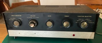
I have a decent-looking, working Heathkit SA-2 amplifier for sale for $350. This unit has the famous 51-29 (made by Stancor) output transformers that are capable of excellent performance. The SA-2 is basically the stereo version of the highly-regarded Heathkit UA-1 or UA-2 mono amps while it also has a preamp and phono section. Shipping is at cost from Illinois, USA. 61821.
The unit looks acceptable for its age with a few minor scratches, but would look nice with some TLC and cleaning. I’m offering the unit for sale with the full tube complement, except the two 12AX7s and 6AN8as. The rectifier is a brand new JJ GZ34, two good used 6AU6s (I don’t see brand markings) and a matched quad of those supposedly “lightly-used” 6P14Ps from Ukraine that look well-used but measure fine.
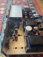
I went through the amplifier and it is playing right now as I’m writing. Since this amplifier works, it would be ideal for someone who wants to rebuild it in phases, making sure you can hear the improvements was you go through replacing old parts. There is a slightly audible hum but otherwise sounds quite good. I performed some testing and minor updating, including installing the yellow-sheet diodes modification to protect the GZ34 rectifier.
I brought the amp up slowly and reformed the large power supply multicapacitor. It tests good, so I believe it is fine for a while. The cap feels warm but not hot even after few hours of listening. The shared cathode capacitor was replaced with a new Nichicon “Audio Grade”UKZ. I measured the other 10uF/25 V electrolytic caps (cathode bypass in phono and pre-amp) and they seem OK, so left them alone for now.
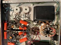
All the coupling capacitors were replaced by good Orange Drop (CDE 715) film capacitors. The small mica and ceramic caps were not replaced yet, and probably doesn’t need to be replaced at all. The under-side photo shows these new caps.
The next renovation phase would be the resistors. I spot-checked the resistors and some have drifted - some not much but others enough to justify replacement. The phase inverter resistors (47k, 1 watt) on the 6AN8a triodes are not closely enough matched to my taste. This could be the cause of the slight audible hum. I’ll leave that work to the next owner.
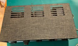
Below are some photos that should help you assess the amplifier condition. Shoot me questions if you have any.
There's a lot of build blogs etc, but they're mostly folk with big workshops and all the tools they need.
I'm building these in my cramped garage with basic tools and minimal experience, as and when I get time...
So far so good if I'm honest and I thought I'd share my experience.
Got my 2 sheets of 18mm ply from Wickes (UK) and whilst the quality is probably not the best, it's all I can afford to spend.
In the absence of a table saw, I've actually splashed out on a track saw. I figured it was the next best thing. I used a normal circular saw last time I built speakers and even then, I struggled to get perfectly straight and equal cuts. A pain when it came to glueing up the cabinets.
Have been used shortly in a project, but pristine condition and original packaging. Gapped at 35mA. Current price from Monolith: €354,80/piece
Asking €450 for the pair shipped to almost anywhere.
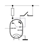
I want to make an "Off" switch on the target pin of the tube so that the green light is not visible at all.
I can disconnect all HT from the tube, but please do not discuss this.
Will turning off the target pin degrade the tube parameters?
Hi guys.
This time I have a Rivera Slavemaster M60 amp.
It sounds great, btw. The issue with this amp is when the SlaveMaster or effect loop are activated (either manually or with footswitch) only a buzz comes out of the amp.
I cleaned all raleted connectors, relays are working. I think it might be the photocells.
Anyone else had this problem?
I cannot find the replacement part (HTV brand P873-G35-201B). Are there any replacements I can use?
This amp will take about 12 to 15 seconds to oscillate then it will play audio.What can I do to shorten on that long delay? Rail caps get fully charge in a few seconds .
My name is Sonny, and over the last few years, I have been getting into Hi-Fi. As part of my A-Levels, I built some 2-way bookshelf speakers early this year. It was a fun experience, though I have only got them back from my school last week. After giving them some time to let them break in, I have noticed that the woofer was slightly lacking in volume compared to the tweeter. While for now i am happy with the speakers as they are, at a later stage, i might redesign the crossover and/or the port.
These speakers are currently hooked up to an old Sony ta-1066, which works OK, though now i have the DIY audio bug, I want to build an amplifier. I think that some sort of lm3886 Gainclone would be the way to go, and a vast improvement from the old Sony. Would this design be a good one to go for?
I'm embarking on a project to overhaul my Studiomaster 16-16-2 mixing desk (actually 20 channel with a four channel expansion). I think it's a decent sounding desk and I've made some good recordings on it (https://ditto.fm/cowboy-films if you're interested) but the pots and faders are all scratchy, despite efforts to clean them, and there's too much noise/hum for my liking. I overhauled the PSU about two years ago, replacing all the electrolytics, and that went some way to reducing the hum but I'd like to do a full overhaul now.
Firstly, information on this desk is scarce. I can't find any schematics online so I suspect I'm going to end up having to trace the circuit from the PCBs. If anyone has any information on it, that would be fantastic.
This is the desk in question:
It has 20 channels, 16 busses and tape returns, three band EQ with swept low and mid, two post-fade sends and one pre-fade.
The construction is semi-modular, with individual channel cards linked together by push-on connectors. One long connector carries power and busses/auxiliaries and the lower smaller connector carries 8 more busses. There is a separate ground wire soldered to bus wire on the faders. There is a lot of room under the channel cards at the back if anything needed adding.
The channel cards look like this:
The design seems very basic:
The mic preamp looks like it's four BJTs into a TL071 op-amp.
The three-band EQ uses a single TL072 (I don't know how).
The line input just feeds into the mic preamp via a pad.
There are no other op-amps on the board. The insert send it driven directly from the EQ op amp, the return drives the fader.
There is no post-fade amp, the fader connects directly to the pan-pot which then drives all 16 busses, the stereo bus and the auxiliaries.
The clip indicator is hidden under that switch board on the right.
There is a single mylar decoupling capacitor between the power pins on each op amp.
There are no mute switches.
So far, my plan is:
Replace all pots and faders.
Replace all electrolytics.
Modify pre-fade send to be post-fade.
I am also considering the following:
Is there any point replacing any of the mylars? (the consensus seems to be no so far.)
Could mic preamp performance be improved by replacing the 5% carbon films with better matched metal films?
Could hum be improved by replacing the bus grounding with a star-grounding arrangement?
Are there any other modifications that could be made to improve things.
I've also been semi- considering some 'advanced' modifications:
Adding a PCB with a separate line-input amplifier instead of the padded-down mic input.
Adding mute switches
Any help/suggestions would be greatly appreciated. I'm in no rush to get this done so while I've got it apart, I might as well do as much as possible within reason.
Hi, I have a Teisco S100P and it has a problem I can't solve. When I play the keys in sequence, I hit a run of four keys which sound they are being modulated in some way or part of the cycle generating the sound is missing. If I switch the octave, the problem simply moves up or down the keyboard depending on whether I select up of down. Given its symptoms I don't think it's anything to do with the keyed or contacts. I think if I could understand how the synth makes the sounds, that is the oscillator section I might be able to figure out what’s going on. Could somebody please explain how the VCO works from the circuit diagram below? Thanks.
I’m going to build 2.5-way speakers. My 1.25” tweeters can go as low as 1.5kHz. And my 10” woofers can reach that frequency.
At first, I plan to wire the woofers as diagram below, the traditional 2.5-ways configuration:
Unfortunately, I just found the woofers are stamped 4 Ohms on their magnets, and, the measured Re showed results of 3.6 Ohms. So, they are rated 4-Ohm drivers.
Accordingly, is the diagram above still usable? Because the diagram shows two woofers connected in parallel to each other, although there is a L3 in series with the second woofer. If not, please suggest me the more suitable configuration.
And now I have a problem with the batteries (they stopped working - probably from prolonged lack of use)
I'm trying to contact them via the email address on the website but no one is answering me.
I would appreciate it if someone could direct me on how to reach them. I have a few more questions regarding the functioning of the system (which I didn't get at the store I purchased from as I mentioned above)
And in any case, I would love to know if anyone knows this brand? Does anyone have experience with this model over time? Are there any faults that have been discovered or is it of high quality and worth the investment (its price tag is high compared to its counterparts in the category)
I have received multiple requests to offer the XSD speaker cabinet as a flatpack. After speaking to my business partners, we think we can offer flat packs made of 3/4in birch plywood on the front and base plate, 1/2in birch plywood on the side wings, and MDF for the woofer array. They will be professionally CNC’d and so the fit should be perfect. You just need to do the gluing and screwing of fasteners yourself. Then finish them with your favorite paint/stain/varnish.
There is a separate GB for the crossover and the waveguide here.
You can listen to is here: Login to view embedded media
The flatpack will not have an interchangeable sub baffle for the midrange and tweeter like the prototype shown above. It will be cut for the PRV 5MR450NDY-8 midrange.
Here is the 3/4in birch veneer poplar plywood flatpack. Woofer array is MDF. It looks really nice and cosmetically perfect “Tru-Ply”.
Edit July 9, 2023:
Flatpacks will be $600 plus shipping in CONUS from Texas about $130 to $150. Flatpacks will be securely packed in foam, hard cardboard corners, strapping and exterior box. Send me a PM with your PayPal account name and address so that I can calculate shipping. I’ll send you an invoice.
Hi all, I have an immaculate Accuphase DP-65V Cd Player which does not work. It is a beauty of a CD player, built like a tank and in almost new condition. The mechanics are the same as the ones used in the Sony CDP 707ES. it has a magnetic sled moving the laser pickup and a very solid metal like CD tray.
The problem is that the tray opens and closes perfectly and very smooth. But once the CD is inside the motor does not spin and the sled with the laser pickup does not move.
Nothing happens. I replaced the complete laser with a good one (supposetly) but nothing improved. It looks like there is no power somewhere. I checked the power supply and there are three voltage regulators supplying two of them 8V and one 5V and the voltages are correct. The drive board has connectors with the voltages marked. One is supposed to input 7V but does 8.64V instead. Since no Accuphase manual is available i am trying to use the Sony CDP 707 schematics but am lost at this point. Any help available to try to fix this player before dumping it? What should I check?
2- ALSWR Didden-Jung super regulators, 4 pcs, using AD825. Used for the above project and set to +3.3 (2pcs) +12 and -12V.
Didden Jung PCBs (1 pos, 1 neg)
They were supposed to be fully working, but I have never fired them up...
I paid 90 Euro (80 GBP) for the lot, so if someone will give me the same (plus postage), they are yours.
I would like to ask you a question.
What are the advantages and disadvantages of the two types of cut-off frequency equalization of the following Mosfet output stage:
The cutoff frequency in the same in the two solutions.
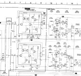
I am currently trouble free shooting an issue with my Bogner Shiva EL-34 Reverb Combo (Serial Number: 035056) alongside my technician. We are experiencing noise problems that appear to be coming either before the phase inverter or possibly within the reverb circuit.
The technician has already worked on shielding the pre-phase inverter tube, but the issue persists. Without a detailed schematic, it is challenging to determine the exact source of the noise. Anyone that provide a partial schematic covering:
As you know, our test files are produced via the PGGB upsampling software. This is because it’s the highest performing audio resampling filter of which I’m aware. My only reservations regarding the PGGB have been it’s cost, which reflects it’s performance. (A quick aside, if you recall, our thread members are generously offered a 50% discount by ZB, author of the PGGB). Plus, the fact that it’s extreme performance necessitated it work offline. In other words, it doesn’t support real-time streaming content, such as from disc or the internet.
First, a disclaimer. I believe the below information to be correct, however, the responsibility is on you to verify all details. That said, ZB has just released an essentially real-time version of the PGGB, and which functions as a Foobar2000 plug-in. Even better, this Foobar version is free for download and use! So, you now may upsample, downsample, dither and experiment to your heart’s content, and at no cost.
As I understand it, the main performance limitation here is the maximum number of filter taps. Which is ONLY 2-million, in the free version. If you desire, a license may be optionally purchased which expands the maximum filter taps to 1-billion. For reference, the offline version PGGB supports a maximum of 8-billion taps. Ridiculously large figures for an interpolation-filter in either case. It’s an effective business strategy when a company manifestly believes in the benefits of it’s product. No risk for potential users to find out what PGGB technology may do for their listening enjoyment. Enough talking by me. Below is a link to the ‘remastero’ website with the intriguing details.
Hi, I want to add a Bluetooth receiver board to an old Onkyo amplifier that I use in my basement workshop. I'm looking for a PCB board that receives Bluetooth and has a line out and runs off DC 5 to 12 volts, split rail or single power. It should be near-audiophile quality, not looking for a toy. I have plenty of space inside the chassis for a board up to 3 inches square. I will internally re-wire the Aux input source to this board. Any recommendations would be great!
new member from Austria here.
I like to repair and tinker with used audio equipment and have build a little workshop.
The extensive thread about the marantz cd-63 draw me here.
I'm a mechanic engineer, so my electronic skills are somewhat limited though.
Up for sale is my single NOS THF-51S. It's been waiting for me to do something with for about 12 years or so. Since it hasn't happened yet I'm thinking it's time for someone else to put it to use.
The attached pictures show it passing the DVM tests and no further testing has been done.
Greetings all,
I was here for long time as a reader but recently I have purchased Gryphon audio system and I would like to know more about them.
System is composed of Preamp and a power amplifier.
1- Gryphon LE limited edition 91 of 100
2- Gryphon DM 100 limited edition.
I did some research but. I couldn’t find detailed reviews. Since these seem to be old models. Please if you know any information about the models like when was manufactured or specifics design criteria it would be great. By the way the system sounds fabulous in my room.
Hello to everyone gathered here on this "mathematical noise" forum 🙂
I have studied, finished and worked as an artist. And as such had loads of friends musicians as well. My father is a classical guitar musician. so from my childhood I was exposed to proper harmonics, have developed musical ear, played folk string instruments, singed in children bands, but was not hooked to music as musician, but art. It was interesting for me to find out that these too spheres "sound" same, just approached differently.
My father could not "understand" how I am attracted to "modern" music ( Underworld, Phex Twin...) and not classical compositions. Funny enough I never could imagine classical landscapes would attract me either. - But time changes everything.
And now I love to listen to "soft" classical Jazz, Harps, and especially lean on upright bass lines.
So how I end up here? Well, I accidently stumbled upon Perry's Marshall thoughts on open baffle sound concepts, and Open Baffle builds and got just hocked with an idea to build ones...
MARANTZ SA-8260 SACD PLAYER
This is a page(s) dedicated to the modifications I have done to the Marantz SA-8260. The Marantz SA-8260 is a first generation sacd player introduced by Marantz in 2001 and discontinued in 2005. I purchased my first 8260 in October 2003. I began modifying this player a couple years later, which has been an ongoing process up to the present. This player can be made into a two channel player that can rival the best players out there. While the player comes as a multichannel player, there are now much better options for multichannel playback than the 8260. Everything contained herein, is for two channel playback.
First up, some useful links:
1. Ken Tripp’s excellent webpage Ken's - Audio and Home Theatre Pages scroll down the left side to construction, then click on SA 8260 mods. Ken’s page is a good introduction to the player and was exceedingly helpful when I was starting out. It is still a good information source on how to install an aftermarket clock.
2. Ray Vandersteen’s excellent website, Ray’s Audio Pages, Ray's Audio Page is a reference site. See the SA-8400 page, as much here applies to the SA-8260 too.
I began modifying my 8260 in the usual fashion, by swapping out various parts, much as mentioned on Ken Tripp’s page. IMO, this is a waste of time, other than for getting practice at desoldering and soldering parts on the Marantz boards.
The modifications I have finished with, and described down the page are the only ones I consider worth doing. Nothing is overly complicated or overly expensive and requires no specialized knowledge or techniques beyond basic soldering skills.
While this page is a few years late in coming, nonetheless there are still a lot of these players out there. The player's performance can be improved a great deal by spending a lot of time and some money on them to get performance on par with the top players in both rbcd and sacd playback.
The modifications will be listed in separate posts following this one.
Hi! I just wanted to check if anyone else has experienced this: the DATS software (v3.16) crashes on start-up. It renders the user interface partly for a few seconds, then just disappears. I just bought my DATS V3 rig, so this is not was I was hoping for 🙁
Notes:
- I've rebooted my computer after installing it.
- I've set the audio device settings to stereo 44.1/16.
- I've tried different USB ports.
- The blue light is on the hardware.
- There's nothing connected to the alligator clips.
Anyone got pointers on what I could try? Does it need any runtime frameworks like a spesific version of .NET or something?
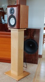
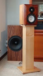
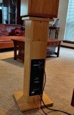
I just completed a new active 3 way system. I used a pair of Hypex Fusion FA253 amps.
Woofers are SBA SB34NRX75-6, in a 70 liter sealed box. The ideal sealed box for this woofer is about 110 liters, so I used a Linkwitz transform to adjust the response. boost starts at 38 Hz, and by 26 Hz I have 6 db of boost. The crossover to the mid is currently 200 Hz LR4.
The mids are SBA SB17CAC35-4, an aluminum/ceramic 6 inch driver. The box is 10 liters sealed. The cabinets have 1.5 inch roundover on the sides, and a 30 / 60 degree dual bevel along the top.
The tweeters are SBA SB26CDC-C000-4, an aluminum/ceramic dome. Crossover from the mid is 2 kHz LR4.
The Hypex DSP features are powerful, and I was able to equalize all the drivers flat through the passband and stopband. I applied digital delay to the mid and tweeter to bring all the drivers into the same plane as the woofer. The Hypex amp is mounted in the speaker stand.
I am not done fine tuning the filters, but I am going to listen to them for a few weeks before I make any further adjustments. They sound pretty amazing right now.
Thanks for everyone who conversed with me over the last 7 months. I learned a lot, and this project would not have been successful without the DiyAudio community.
They boast that there is 100 hours of CAD work to do this design. I do lots of CAD work drawing loudspeakers. 100 hours is a joke … some drawing sets i do take a fifth that much, that is with flat sheets. As Chrisb says, curves cost money. 1000 hrs is more realistic.
Hello everyone !
I was looking for a simple audio compressor to pair with a microphone for live use, dedicated to the microphone. What do you think of this one? It has many interesting settings: input gain, ratio, threshold, make-up gain, THD set
I want to make pcb copies of this audio compressor. I tried to reproduced the schematic on EDA, this is the original link : Compresseur audio Sonelec 002 (for private use)
I have several routing attempts, I don't know which one is the best in the end because it's the first time I've tried this. I have a user constraint for the design of this PCB : place all the potentiometers on the front of the chassis, in direct soldering without additional wires. This is why I start with a PCB border of approximately 130x90mm. I only applied one beginner's rule... keep direct connections between components as close as possible.
what do you think about the schematics and routing suggestions of EDA ? I used automatic routing. With 2 layers there are 6 vias, with 4 layers there are 3 vias. No error messages, EDA indicates when the tracks are too close to each other...
Photo n°1: original schematic (x2 mono with link option). SW1 is a switch to connect two PCB together.
Photo n°2: my reproduction on EDA (x1 mono). what is not clear to me is : what happens to 18v and 18va written on the original diagram, at the time of automatic routing ? In my version, power is named "ALIM"! after routing (without error), the two tracks 18v and 18va of the original schematic disappear, can you explain to me why?
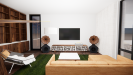
I've been lurking here for a long time with some moderate contributions, and have been scouring the forums trying to understand a direction for a custom speaker I'm building around the B&C DCX464. Really, it's being designed around aesthetics - I have always loved the look of big wood horns ala Oswalds Mill Audio and A for Ara. I know the two aforementioned companies build luxury items for a price point that is out of reach for almost everyone, with a sound quality that can likely be achieved for much lower; however, I'm an architect and one of my fatal flaws is that I like how things look as much as how they perform.
The design for this speaker thus started with a visual idea more than an acoustical one - I wanted a big (24" +/-) round wood horn set atop a bass cabinet down below. In looking at several options, it appeared to me the best way to achieve this was to 1. keep the crossover point relatively low (to achieve more flexibility in driver-to-driver spacing) and try to play as much of the frequency range from the horn to keep it as point-source as possible. I saw the DCX464 reviewed relatively favorably on Joseph Crowe's site, and given its broad range and low crossover possibilities, I thought that driver might be the ticket.
I use a program called "Rhino" for work, almost 8 hours a day, and have been for nearly 15 years - so there is nothing outside my capability for modeling. I am also an expert in a parametric program called "grasshopper," so I've been able to translate some of the more complex math involved in various designs into parametric models that allow for extremely fast and quick experimentation (I have built a pretty comprehensive model that allows me to iterate through tractrix horn constructs with petals). I have a 3D printer and a CNC and have been building furniture for 25 years, so there are few things outside my fabrication abilities.
Where I quickly fall apart is trying to determine what exactly the geometry of the actual horn/waveguide should be. I have read a lot of different opinions, but realistically what I'm looking for is good sound that works on a relatively wide dispersion - it doesn't have to be the same EVERYWHERE, but I'd like to avoid a full-range pin-point sweet spot if at all possible.
I've been looking at a lot of other precedents for contemporary horn drivers, including the Oblate Spheroid waveguide, Joseph Crowes ES290 horn, the Advance Transition Horn EXAR, and tractrix horns in order to try to find some commonality between all of them in the design. I have drawn all these in CAD and plotted them for comparison.
I'm also curious about the "pleats" in the X-Shape waveguide (mostly because I could fabricate and think it looks cool) - but don't really understand what it is doing acoustically. https://audiohorn.net/x-shape-horn/
Attached is the curve plot comparison, as well as a couple of early renderings of what I think the cabinet would generally look like. I was looking at the Faital Pro FR400 for the lower end. I'd be doing an active system with maybe a passive crossover for the compression driver. I'm looking for opinions - about horn design, general thoughts on the speaker design, etc. Thank you!
Anyone ever use a Push/Pull pot to add volume and balance control to the Pass B1 buffer? If so how did it work out. Any problem with noise when pushing/pulling to adjust? Any ideas on best way to wire it in? Thanks, Tony
I'm in need of a replacement for this resistor in my MEP803A generator. It's designated "LED resistor" on the schematic and is in series with the AC interrupter. The resistor failed last week and I've got a couple of alligators and a couple of cement resistors temporarily jumped in, but I would like to find the correct part. All of the electronics supply houses have them as non-stocked items, but if I want to order 180 pieces, they're happy to order them. LOL
I am trying to find a copy of Gary Pimm's solid state version of his Tabor amplifier. Tried the Wayback Machine but keep running in problems. If anyone has a copy, would be much appreciated.
I’ve received this amp for repair but previous tech had mixed parts inside, I’ve come to think that the 1405’s are the original but none shown here are available to me, can I go with 064N if yes what’s the best gate resistor to use currently there are 39ohms but I don’t have that resistor currently, any thoughts?
Hi I am currently using a 27TAC/BG in a 12 inch 3 way system. I am considering trying the Satori or Scan Speak version of the Textreme dome tweeters. Has anyone used them? Are they of higher performance tan the driver I am using? Thanks
I have a Nad 314 with Mordaunt Short MS10i speakers, Cambridge Audio CD4 and Dacmagic2, bought in the late 90s. Over the years the bass became more loose and rumbling, and recently one of the woofers went open circuit, so I purchased some Wharfedale 12.1 as a replacement. I also replaced all the power capacitors in the amp.
The wharfedales are bright and sound good with vocals, but the bass completely overpowers any bassy tracks, especially electronica.
A discussion with Richer Sounds points me to the amp rather than the speakers which was my thinking too.
So, after reading for a few days, I'm trying to decide if replacing all the capacitors in the NAD will fix the issue - or perhaps just replacing capacitors which affect the bass? 3 of the power capacitors were around 30-50% of their rated value.
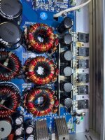
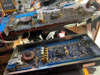
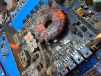
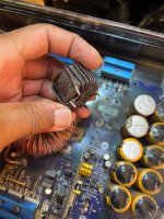
Did a power supply rebuilt on one of this amp many years ago, now the customer wants to decommission one to restore the other, board was burnt to cinder back then so a lot of jumper connection was mandated. Now all I’m to do with the better looking one is take the parts from the bad looking out of chassis board and repair the one that he brings in the chassis. May the good Lord be with this restoration. 🙏
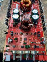
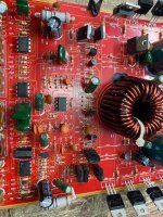
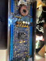
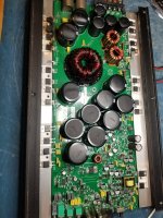
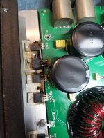
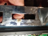
Hello everyone. I have a mtx 1501d that is in protect mode. I am a seasoned tech and work on a ton of home audio gear but am very new to auto amplifiers. I would like to get this thing up and running. I cant find a service manual for this amplifier and am hoping I can use this amp to get me more familiar with auto amplifiers. I popped the top and found four HUF75339P that have been destroyed. Looking at the speaker terminal strips it appears someone was wiring subs up to this amp while it was on and shorted one of the wires to the case ( arc marks on the case). Nothing else in the amp looks visually bad. I ohmed out all the ouput transistors and they dont appear to be shorted. Il post a couple pics. Are these fets still in production or are you guys using modern replacements? I work on a ton of vintage amplifiers and allmost allways need modern replacement. Anyhow if you guys can kind of give me some tips or help with this that would be awsome. I will post a couple pics and look forward to hearing from you guys.
Since I would like to make cut outs for the Raspberry outputs on the rear panel of my DAC enclosure, does anyone know if 3D STEP models of Ian Canada's boards exist? For me it would be much easier to assemble the boards with CAD software and project the lines of the various connectors.
Hello, I have develop this pcb for volume control,I do have severall modules and parts from National Semicondutor
but this have been developed mainly for the ones with LM3875 which you can check here: https://www.ebay.de/itm/325923530044
Here I am using a RK27 ALPS dual gang pot,but I am looking for a better price point using other pot, and I would like to know what forum users do recomend?
Good morning everyone, making my obligatory introduction post. I've been a big music nerd for my whole life but never really had the budget for any high end gear so have mostly stuck with midrange headphones or vintage scores from craigslist etc. Just bought a house with the SO and working on furnishing so I'm thinking its a good time to integrate a good audio solution. Current daily driver is a 1968 HH Scott 2550-W "Scottie." Funky little solid state bookshelf receiver with matching enclosures that I scored for $50 nearly 10 years ago. The drivers were trashed when I bought it so I swapped them for some bose 6.5" papercones from the parcel shelf of an early 2000's mazda millenia. Complete swag on my part but ended up being a nice fit sonically. This little guy is great (likely needs some recapping) for an average sized bedroom but runs out of my steam in my open plan dining room/kitchen.
My current plan is to grab a single ended EL84 amplifier (some china junk but very workable with some simple mods from what I have seen) and do a full range build like pencils or something similar. I'm a little stuck on driver selection and that's why I'm here.
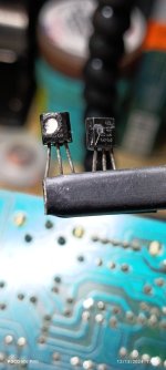
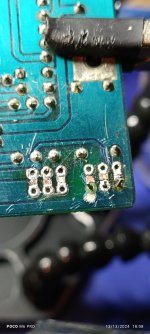
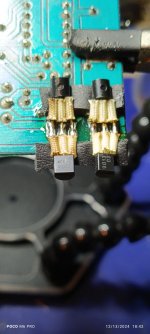
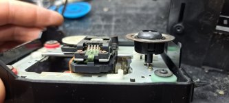
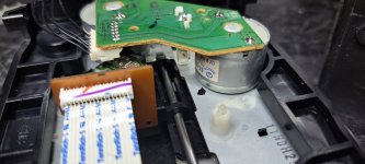
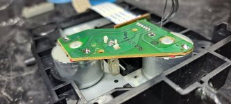
@Mooly, Hello, I would like to ask you a question about a JVC mini system, the laser pickup is a SOH-AAN -04H, at least that's what the label says.It's strange what I found, at least for me, I notice that it takes a lot of work to read the TOC, but once it does, it doesn't start on track 1, I order it to go to 2, 3, etc. and it does it without problems, it reads perfectly and if I send it to number 1, it executes perfectly, if I change the disk, the process repeats itself. I thought it might be dirty in the pickup position sensor, but here's the thing, I attached some photos, the sled doesn't activate the switch, there is no physical contact between them and it seems like there never was, it doesn't seem like any part is missing or broken. Is this possible? According to the service manual, the switch signal carries information to the MCU.
Hello everyone.
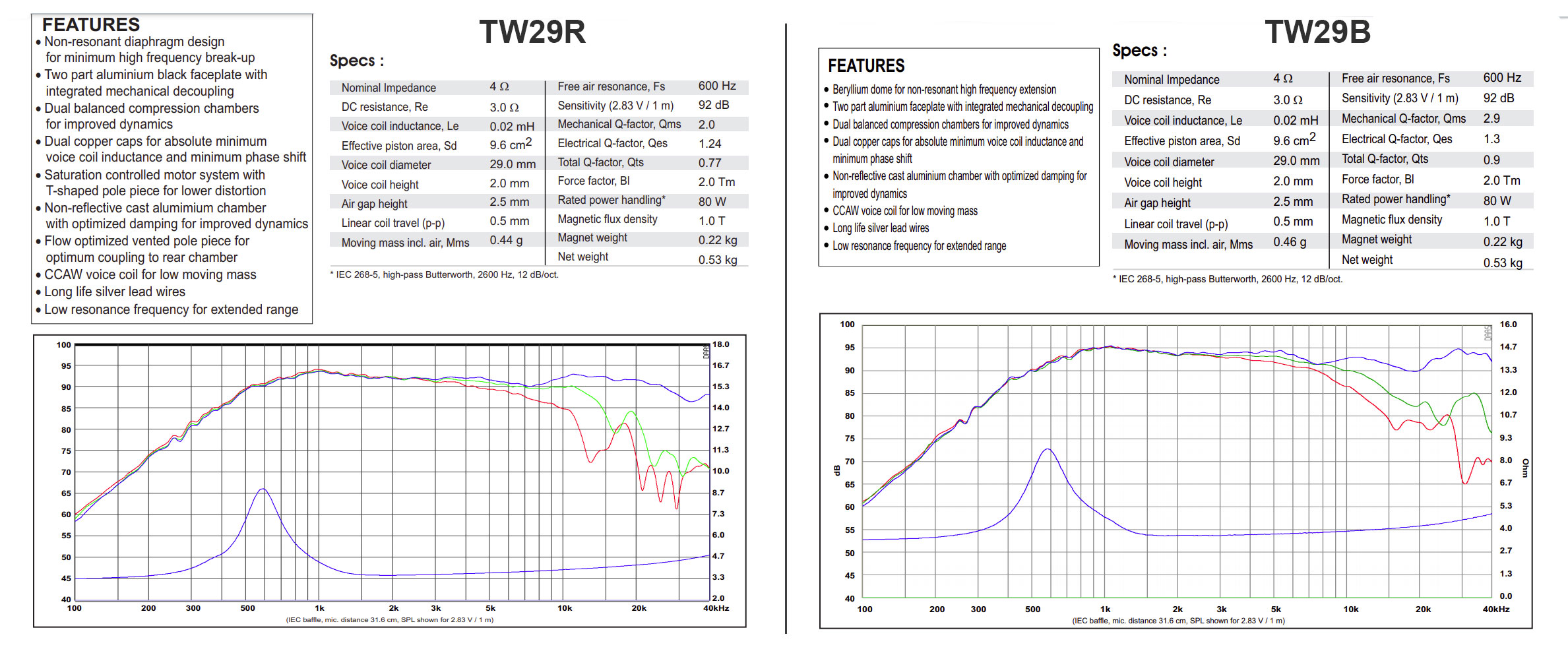
I would like to try using beryllium TW29B in the Kairos Kit.
The TW29B and TW29R are identical in datasheet. Is crossover correction necessary in this case? Has anyone tried beryllium TW29B instead of TW29R?
TW29B: SATORI TW29B-B / Beryllium – Sbacoustics
TW29R: SATORI TW29R-B / Fabric – Sbacoustics
I have a c-28 solid state preamp using it on my mc-2500, and my mc-7270. I seem to be quite disappointed with the sound quality of it. It just doesn’t sound clean and clear as a MAC should. Even with the bass trim turned down, the musical clarity of the bass + treble tones etc. just isn’t as defined as I thought they would. It just sounds mushy, noisy, boomy and tasteless. I own several other MAC pieces, but I’d just like to know if this particular preamp is a reputable pre, or should I just get rid of it and try something else in its place?.
Anyone who’s tried this pre please let me know. Maybe one of the other MAC would fare best. Please help me. Thanks y’all!
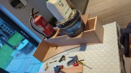
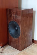
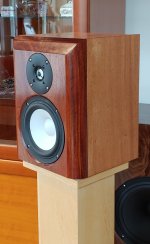
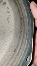
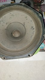
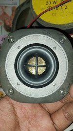
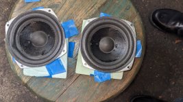
1. Is this tear repairable? If so how?
2. Why does the cone look wet around the edges
3. How do i clean the dirt off the speaker.
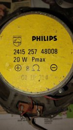
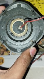
4. Are those tweeters even real?
5. The tweeters seem to be hooked up directly in parallel with the speaker. Is this okay or the resistor i found goes in somewhere.
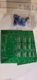
I have started to build my portable speaker and I run into a problem. The crossover that I build does not work properly .Can someone help me
With the best regard Casian ( I am a beginner and I am new to the forum so please understand my shortcomings )
Judging from the cutout of Lavoce's 1.4" drivers, we can see a very interesting phase plug design where the phase plug seems to end right at the start of the driver exit.
Such a design with no exit angle should make mating to a horn/waveguide smoother. Has anyone tried these drivers?
“A Champaign lifestyle on a beer budget” may not be possible in general, but I believe is somewhat attainable in audio. I would like to replace my Yamaha receiver – CRX TS10 – with something (hopefully) better. My budget said class D. But I read a lot about “power”, but nothing about “musical.” So I searched for a good used A/B. The Nakamichi SR 2A (30 RMS into 8 ohms; 45 max; 55 max into 4 ohms) designed by Nelson Pass and received some very good reviews (https://bargainaudioblog.com/2018/05/13/nakamichi-sr-2a-stereo-receiver/ ). This has set me back $127.00, but was in my budget. Now for some speakers. Therein lies the rub (Shakespeare?).
I checked all kinds of reviews and eBay listings. I could find nothing suitable for less than about $400.00. I have in the past made a some speakers from the Madisound website for my tube amp – long since gone. So why not build again?
I viewed a number of “Kirby meets audio” videos. He recommended 2 Dayton Audio PS 95-8 3.5” full range speakers (85.56 db 2.83V/1m; 10 watts) and a Dayton Audio DCS 165-4 ( 87.4 db 2.83V/1m; 100 watts). This, plus about $70 in hardware, 14 gauge wire, fiber-fill (etc.) will set me back $170. This is on my Parts Express order, but I have not yet pulled the plug.
As of now, I have about $300 potentially committed – not a lot for most people, but a fair amount for me. But what price audio nirvana? (yeah, sure…)
The reason for all the specs is because I built a number of projects, I still do not understand electronics very well. If the instructions say “solder wire from point A to point B,” I can do it. But don’t ask me to explain why.
Now comes the question(s): how to I set up these (or other) speakers to best advantage (want frequency response down to about 40 hz):
Separate enclosures for each (wood cost s/b cheap – small boxes). Hook up the PS 95’s to channel A; sub-woofer to L or R of channel B. Play both channel simultaneously and use base tone control to adjust bass SPL. I have no idea if this will work – 8 ohms vs 4 ohms impedance? Will my 30 watt amplifier be able to provide enough juice? Etc. No extra costs.
Separate enclosures for each but use a crossover in one, output to 10 ft wire to sub-woofer. But will this work? Impedance mismatch on speakers a problem? Etc. Extra costs: some hardware and crossover components
Add a Dayton Audio DTA-2.1BT2 100W 2.1 Class D Bluetooth Amp for $85.00. Or the Dayton Audio SPA100-D 100 Watt Class-D Subwoofer Plate Amplifier for $90.00. Or the Dayton Audio work if no RCA low out from my amp? The first one was recommended by “Kirby meets audio,” so it must work somehow, but these is no Bluetooth in my system. and no low frequency out. This second option seemed to work per a previous thread - see https://www.diyaudio.com/community/threads/connecting-a-single-passive-sub-to-stereo-amp.371607/
Use 2 speaker/cabinet design. Keep the PS 95’s(?) and use different woofers(?). Net costs: unknown – may be less, probably more.
Well, there you have my potential stereo upgrade options. Are some of these completely not doable? Are there better options? I am open. My expertise is limited. As in I have never designed a crossover network.
Music preference: classical, 50’s jazz, vocals, some 70’s rock.
May thanks in advance for any comments/suggestions.
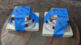
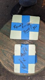
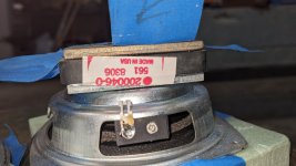
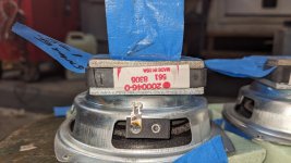
I had these small (looks like Acoustic Research) reconed. Trying to find any information on those.
Heard they might be used in a small 3 way ARms1? Any info? Anyone needs them?
im new to amp repair as far as getting into reading component values and undersanding how it actually works.. i have an cheap oscope but not sure how to really use it..
so i have a hifonics brutus 2016.1d that powers up but has no sound except a loud pop when i turn off the power.. thinking about it this it might be cuz im just cutting the power supply and not turning off the remote first.. ill try that next time..
1 side of output fets read 77.5 volts on the drain and the other side reads 77.5 volts on the gate and source is that normal?
i found a chip on the driverboard was burnt so i ordered a new one based on what i found online was chip lm211 and it was a bit larger than the one on the board.. i put it on anyway.. i know not the right move im sure but what should i be checking and whats the correct part to order?
Has anyone tried running one of these drivers down to 600 Hz in an appropriately sized horn with a steep electronic filter?
BMS themselves actually rate it from 500-20 000 Hz.
Seems to handle even 110 db at 600 Hz on the Dayton H812 so I can't imagine it being an issue in a domestic setting:
I forgot that I had posted an old version of this scheme here, in the The Hundred-Buck Amp Challenge thread, until an user of a Brazilian forum reminded me of it today. Coincidentally, the first name of this amp was 100Buck Amp.
It is a 2.2W amp, EF184 + 25L6 tubes, with a really good sound. The power transformer is a ordinary 30+30V 30VA. The output transformer is a 1.7K - 8 ohms SE .
Here you can find a review of this amp (in portuguese): Crow | The 100 Buck Amp | REVIEW por Zarbinatti - YouTube
You can build it for less than $100...
And here the last scheme:
*If anyone wants, I can update the PTP layout of this amp and post it here.
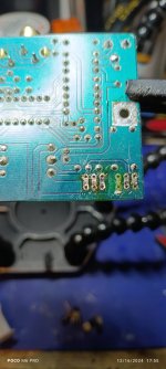
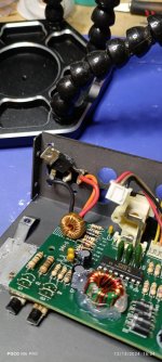
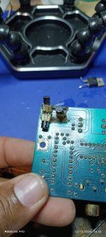
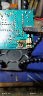
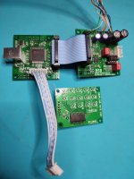
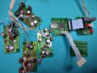
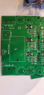
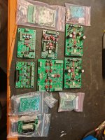
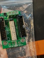
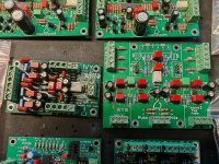
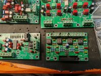
Years ago I bought a set of TPA kits, then forgot then in a closet. Just found them and I don't need them any more.
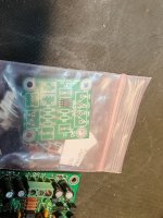
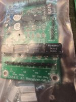
Seems like they are soldered by a beginner, not me. On some of the boards there are parts missing and cut or shorted, refer to pictures. Some are unsoldered kits.
I will prefer to sell them all at once. Price for the complete lot is 70€ + shipping.
See photos for details.
-2x Counterpoint
-2x Sidecar
-IVY 2.0
-IVY III sold
-S/PDIF module CS8416
-4-channel S/PDIF level converter
-CMP1 v1. 0
-OTTO II
Hi everyone! This is my first thread on this forum.
I'm planning to build an amplifier to drive a pair of 8-ohm, 15-watt speakers I have. They're reasonably priced but capable of delivering decent sound quality.
I've decided to use a couple of LM1875T-based amplifier modules for the power amp section. These modules require a dual-rail power supply. I'm sure many of you are already familiar with them, so I won't go into further detail about the modules.
I'm considering two options to power them: either connecting two 24V SMPS modules in the following configuration,
or using a toroidal transformer with a full-bridge rectifier and some smoothing capacitors
(I'll check if they're completely isolated from the mains supply before connecting the pair in this manner, to avoid any possible short circuits )
I've read in several places that SMPS units tend to introduce harmonics into the power line and generally deliver lower-quality power compared to toroidal transformers. Is there any truth to this statement? I know these amplifier modules are not of premium quality, but I'm eager to improve them in every way possible. I’d greatly appreciate your valuable advice.
Additionally, how much current are we likely to deal with here? The modules are rated for a 20W output each, but I understand they will waste a considerable amount of energy as heat