Using electronic crossover as a bass booster

I’ve been experimenting connecting the outputs of Nakamichi EC-200 electronic crossover in different way by tying low and high frequencies outputs together via Y-cables. The objective is to use it as a bass boosting that is splitting low and high frequencies apart for allowing level adjustments independently and merging them again before sending it to a single amplifier, see attached. The unit was inserted at tape minitor loop of the preamplifier section of the integrated amplifier. Normally, the high frequency level will be left at fully clockwise (maximum position). And the low frequency level will be used alternately from min to max positions for adjusting bass level. After experimenting, I found an issue that the signal cancelled (output decreased) against each other when the low level knob was set at fully clockwise (max) and fully anti-clockwise (min). But it summed at around mid-rotation. I’d like to ask if there’s a potential to modify the unit to completely perform as desired description earlier.

Attachments

  • IMG_0184.jpeg
    IMG_0184.jpeg
    227.4 KB · Views: 77
  • IMG_0185.jpeg
    IMG_0185.jpeg
    58.2 KB · Views: 79

Audio Aero Capitole II not so special edition!

Audio Aero Capitole Special Edition - Bought back from the dead!!!

I purchased this player in a terrible condition. Someone had decided to "upgrade" the player and pretty much destroyed it!

IMG_4044.jpeg

IMG_4045.jpeg


The Mundorf supreme silver oil caps had been changed to basic film MKPs and the board was completely destroyed around the tube mounts.

IMG_4046.jpeg


Fortunately I was able to clean up a bit and there was enough of the PCB left to recover from the mess left behind!
I have some sub boards on the way to properly tidy up the valve area of the PCB.

For noe I had to fashion the tube legs to replicate the connectivity

Still not as I would like it to be but its functioning...... I'll get there 🙂

IMG_4070.jpeg


IMG_4073.jpeg


Result is its now running and fully functioning as a CDP, DAC and preamp albeit its not as pretty on the inside as it once was.
There's still some work to do, as I have designed new sub PCB's for the tubes to mount to and the caps will revert to Mundorf Silver oil! More than happy to have saved this one!!!!

IMG_4111.jpeg

IMG_4110.jpeg


IMG_4115.jpeg


IMG_4119.jpeg


IMG_4121.jpg


IMG_4122.jpg


IMG_4060.jpeg


IMG_4058.jpeg

Neurochrome 21st Century Regulator and extra parts

Sold.

Complete Neurochrome 21st century regulator kit from a few years ago, never assembled -- did come with surface mount devices preinstalled however.

Comes with extra parts from an even earlier build I did of this board back when you could get a bare board and solder in your own surface mount devices. (I bought extras at the time.)

Attachments

  • regulator (1).JPG
    regulator (1).JPG
    764.9 KB · Views: 61
  • regulator (2).JPG
    regulator (2).JPG
    421.7 KB · Views: 63
  • regulator (3).JPG
    regulator (3).JPG
    453.2 KB · Views: 61

EL84SE with local NFB?

Hi, mainly for curiosity i would like to learn on an EL84SE amp with local NFB.

Imagine a standard EL84SE, pentode mode, kathode bias. NFB is usually being appplied from the 8 or 16 Ohms tap of the OT to the cathode of the stage in front of the EL84.
And what if the application needs a volume pot ore some kind of tonestack just in front of the EL84?
Which means that there is no NFB of this kind possible in a meaningful way - it would depend on the position of the vol pot.

So - applying NFB directly to, say, the cathode of the EL84? Which would, of course require that the cathode condensor of the EL84 be omitted.
That would lead to
a) current NFB due to the missing cathode condensor
b) NFB including also the transformer.

has someone also done this? How would, for example, the stability of the bias point be affected?

Here is Tracy, the trenchant cable-tracer

A cable tracer, also known as a wire tracer or tone generator and probe, is a tool used to identify and trace wires or cables within a network or electrical system. It's particularly useful for pinpointing the location of specific wires, troubleshooting issues, and ensuring proper connections.
Depending on the purpose, you can trace the exact path followed by the conductor, or just locate its destination (end point), or both.
Two main principles are usable: electrostatic or magnetic. Each has a specific domain of application, and in addition, a hybrid, electromagnetic mode is also possible. It is rarely encountered commercially, but Tracy includes it, and it has the ability to solve normally intractable problems.

How It Works:​

  1. Components:
    • Transmitter (Tone Generator): This part is connected to the wire or cable you want to trace. It sends a signal (often an audible tone) down the wire.
    • Receiver (Probe): This handheld device detects the signal emitted by the transmitter. When it gets close to the wire carrying the signal, it produces an audible or visual indication.
  2. Operation:
    • Connecting the Transmitter: Attach the transmitter to the wire or cable using clips or a specific connector.
    • Activating the Transmitter: Turn on the transmitter to start sending the signal.
    • Using the Receiver: Move the receiver along the path where you suspect the wire is located. The closer you get to the wire, the stronger the signal or tone you will hear.
Here is a drawing summarizing this type of operation:

1731599896592.png

For cheap instruments, the generator is just an audio device generating an easily recognizable musical jingle, rich in high frequencies.

For a more accurate pinpointing, a differential operation is preferable:

1731600775471.png


The single-ended electrostatic mode is very cheap and has a wide detection area (too wide!), and the differential mode is very restrictive (too restrictive!).
They are useful though.

This is the 100KHz transmitter:
1731601278956.png


And here is the (kludgy!) receiver:
1731601419979.png

Attachments

  • 1731599859814.png
    1731599859814.png
    57.4 KB · Views: 46
  • 1731600736273.png
    1731600736273.png
    58.6 KB · Views: 45
  • Like
Reactions: AllenB and stv

Integrated Amp (Yamaha) - Diagnose (Power Amp) by Separating Pre and Power Sections

One step I haven't yet tried, in my attempts to further diagnose a one-channel in-op issue on a late '70's Yamaha CA-600 integrated amp, is to use a separate pre-amp and source and test ONLY the Yammy's power amp section. Has anyone attempted that on a Yamaha integrated amp of this vintage?

There's a "Coupler Switch" (see attached) for separating pre-amp and power sections on the rear panel. I've successully used it to de-couple pre and power sections and verified the symptom in not in the pre-amp section. (I.e., when a separete power amp was used in place of the Yamaha's power amp section no symptom was present.) I simply want to, as stated above, use a separate pre-amp and source and test ONLY the Yammy's power amp section. Yet I'm reluctant to attempt that without knowing if anything adverse might occur that's unrelated to whatever may be wrong with it.

If anyone has done this on a 1973-ish to 1976-ish CA- series of Yamaha Integrated Amp, let me know.

Attachments

  • Coupler Switch.jpg
    Coupler Switch.jpg
    314.7 KB · Views: 37

PCB manufacturing

This topic has probably been discussed to death, but Search isn't returning anything useful.

I'm looking at getting a small board made, 2 layer, no bigger than a postage stamp, and low quantity, maybe 10 of., and no urgency.

What/where is the cheapest way/place to do it? Getting it done in UK is preferable but as in a cheapskate, don't mind getting it in China, depending on the cost.

My Dynaco ST 35

I've searched threads here on the forum but can't find any answers to what my problems are and I lives in Sweden and main voltage is 230V.

Now it is that I finally got my ST-35 up and running, but not without problems, even though this is the third ST 35 and a number of ST 70s behind me, it hums steadily at 50 Hz (I would think) but without finding the reason. I has also built couple others tube and ss amplifier and pre amps.

I have tried all possible troubleshooting, also checked online for something similar and as usual there are different variants of solutions.

When I got home (flea find) with the amplifier, I disassembled it for repair and found an error that the previous owner had made when they built it, the error is that one of the cables to one 115V winding that is connected to the 240V version was pinched under mains transformer there was also a burn mark in the chassis, I then tested the mains transformer and it was correct with all the correct voltages and current.

This I have done, the power supply is handled by an EFB by D.Gillespie new home-etched pc13 circuit board all resistors are original or replaced till others from Allen-Bradley. The tubes are original 7247 and new Russian EL84

But when I start it there is a hum that gets louder when the tubes warmes up, when I remove 7247 it is quiet I have gone through the wiring diagram a number of times but I think it looks right no cold solder I have been detected nothing. All tubes are glowing so that's not the fault (I think) maybe the 7247 are the fault. I have non tube tester but a friend have but he lives i a other part of Sweden.

From my search online there could be two faults but one involves other transformers with 4-8 ohm tap but mine are original and it was feedback the other talked about, that 7247 were broken now I don't know if they are broken I have none opportunity to try right now but I'm wondering if the pinched cable might have caused them to be broken. The hum or oscillates on both channels, possibly a little more on one channel.

I hope someone has a good idea how I should go about it, because right now I'm just have no clue about the problem.

Cheers Anders

Mactone MH-300b schematic or photo

Hi
A friend of mine has asked me to fix his Mactone MH-300B.
Problem is it has been at a very unprofessional repair shop that has cut all the resistors and capacitors out and they are now in a plastic bag.
It is a PushPull 300B with 4x300B 2x12bh7 1XECC82 so it is probably a very common topology with fixed bias, but it would be easier for me , if I had the original schematic.
I do not have the amp in house yet, but if the schematic is impossible to get hands on, I will post the measured values of all the resistors and capacitors, and then hope we can agree on how the amp should be ..

Giant leap for phonograph

I am really really happy that I pursued trying to improve my record playing experience. I initially bought and built a VSPS board. When I installed it into my switching preamp, I was not very impressed, as there was the same amount of hum/noise as my el-cheapo phono board from Ali Express.

So recently I decided I would put the VSPS board in its own chassis. I debated, but ultimately decided to include the PS inside the 6x10x2 inch chassis to match my switching pre, and 6LU8 tube amp.

Well, initially when I plugged it in and turned up the volume there was still hum. I tried bringing a piece of shielding between the transformer and the preamp board, and it didn't do anything to reduce the noise/hum. BUT, what did happen was that during handling, the hum disappeared! I then checked the turntable ground and I could get the hum to cut out by moving it a bit. I pulled the ground cable and checked the 1/8" mono phone plug I was using as to what was going on. Turns out I connected the TT ground to the chassis instead of the preamp board ground. Changed the connection and vois la no more hum, even at max volume (with no signal).

Well that made me happy. But what else made me happy is that I replayed a great recording of Beethoven's 5th and my sox were blown off! the bass was really very detailed and powerful, and the dynamics were also impressive.

So, my experience is that this VSPS board (thanks Richard) is excellent. My TT is an old Technics belt drive. I had recently upgraded to a modest LP gear cartridge with elliptical stylus, but my initial impression (with the same record) was Meh. So anyway, I am very excited to have elevated my LP lstenng experience.

Roger

Mooly's MMAMFM Monoblocks - A build log

G'day Guys.

I hereby start my build log for my implementation of Mooly's My Mosfet Amplifier Made For Music.
https://www.diyaudio.com/community/threads/my-mosfet-amplifier-designed-for-music.119151/

Here's the schematic for reference:
sch_2.2.1_rec2.png

I will be implementing this amp design as monoblocks for a couple of reasons:
1) I think their cooler than stereo amps.
2) mono construction, better blah blah blah.
3) My racking situation is much better suited to my power amps being monos.
4) I like making extra power supplies etc.

I am building my chassis from scratch:
1) I have the tools, sheet metal is cheap.
2) Ali express cases tend to not be my style and shipping is horrendous to NZ.
3) I like making things for the sake of making things myself.
4) I can get exactly what I want instead of being constrained by somebody else's engineering/design choices.

Boards have arrived fresh off of the printing press at JLCpcb.
20240219_212944.jpg
Mmmm Shiny!

I've started populating the pcbs however today I will start the story with a peak at the current state of the chassis.
20240219_172139.jpg

On the weekends I tend to do noisy stuff like cutting metal when I get a chance around husband/dad duties.
On weeknights I tend to work on the electronics side around exercise and husband requirements.

At my current rate of work, I would hope to have them powered up for testing in a couple of months.

I love my SEAS Exotics

Yesterday evening I connected my lovely Exotic's again to my Accuphase and listening to them 😍😍😎.

What a wonderfull driver placed into 160 liters 😍😍😎.
Very very smooth and very deep and perfectly controlled.
This is going very very nice.

Description:
Ready B.R. speakers equipped with the very expensive and beautiful full range 8 inch drivers from SEAS with a beautiful flat curve and an impressive superior depth.
This goes very nicely, deep and low with ease.

Drivers with certificate and subsequent serial numbers.
REMARKS:

MATERIAL CABINET 18mm BLACK AND STANDARD MDF.
SIDE PANELS 19mm SOLID BEECH WOOD.
BRACINGS 44x27 SPRUCE WOOD.
PRITEX 42mm DAMPING GLUE TO ALL INNER PANELS EXCEPT BAFFLE.

TECHNICAL DATA:

Driver: Full Range from SEAS type X1-04 EXOTIC F8.
Volume cabinet: 160 liter.
Sensitivity: 96 dB/W(m).
BR port (2x) 70mm diam. x 109mm length.
BR tuning @ 30 Hz.
Frequency range: 29Hz - 20kHz (-3dB). (edit)
Impedance: 4 Ohm.
Long time power 35 Watt.
Short time power 100 Watt.

Two tone cabinets.
Sleek and solidly built.
Transparent satin finish.

------------------------------

Built 2023
M. den Boer
Brielle
The Netherlands.

------------------------------

Attachments

  • 1.JPG
    1.JPG
    103.2 KB · Views: 392
  • 2.JPG
    2.JPG
    106.2 KB · Views: 357
  • Assembly Seas Exotic big_page-0001.jpg
    Assembly Seas Exotic big_page-0001.jpg
    308.5 KB · Views: 415
  • Assembly Seas Exotic big_page-0002.jpg
    Assembly Seas Exotic big_page-0002.jpg
    338.2 KB · Views: 405
  • Assembly Seas Exotic big_page-0003.jpg
    Assembly Seas Exotic big_page-0003.jpg
    234.6 KB · Views: 381
  • Assembly Seas Exotic big_page-0004.jpg
    Assembly Seas Exotic big_page-0004.jpg
    262.6 KB · Views: 369
  • Assembly seas X1-04 EXOTIC F8.jpg
    Assembly seas X1-04 EXOTIC F8.jpg
    128.9 KB · Views: 427
  • IMG_20230226_141409.jpg
    IMG_20230226_141409.jpg
    459.7 KB · Views: 404
  • IMG_20230324_134655.jpg
    IMG_20230324_134655.jpg
    341.6 KB · Views: 419
  • IMG_20230324_134719.jpg
    IMG_20230324_134719.jpg
    279.5 KB · Views: 389
  • IMG_20230324_134733.jpg
    IMG_20230324_134733.jpg
    523.7 KB · Views: 386
  • IMG_20230324_134739.jpg
    IMG_20230324_134739.jpg
    528 KB · Views: 370
  • IMG_20230324_134832.jpg
    IMG_20230324_134832.jpg
    410.7 KB · Views: 353
  • Opstelling Exotic big.jpg
    Opstelling Exotic big.jpg
    280.5 KB · Views: 346
  • Opstelling Exotic big2.jpg
    Opstelling Exotic big2.jpg
    270 KB · Views: 402
  • X1-04_Exotic-F8_Datasheet_page-0001.jpg
    X1-04_Exotic-F8_Datasheet_page-0001.jpg
    371.3 KB · Views: 390

RF Anode /plate parasitic choke for 12AX7 ECC83 input stage

I don't know if placebo effect or not, but my amplifier sounds better if I insert a parallel LR filter in the anode path, just before the usual plate resistor.

This is called RF anode choke or "parasitic choke". Usually I read in radio schematics anything above 1mH should work to purge possible RF noise, with the knee out of the audio band but before MF band.

I put 15K res // 1.5mH inductor, but it was a quite random choice.

What do you think? And which values are ok?

Help with Crossover bypass caps!

Hello everyone & I have a pair of Dahlquist DQ 10’s, been listening to them for over 40 years. I updated the crossovers and would like now to try bypassing caps C1 and C2 with Duelund cu 0.01 bypass caps. What I’m unsure of, need help with, is orientation. Here is how the caps are described:

The outer lead out, closest to the edge of the capacitor, is connected to the outer foil and as such should be connected to the lowest impedance path to ground, generally the signal output.

And, here’s the crossover schematic. If you can advise me, I’d appreciate it and thanks in advance!

Attachments

  • Dahlquist DQ-10 Crossover Schematic 4134 2.jpeg
    Dahlquist DQ-10 Crossover Schematic 4134 2.jpeg
    44.5 KB · Views: 127

JL Audio 300/4 turn on without remote

Hi friends, I am looking for help to repair a JL Audio 300/4 rev 1 amplifier. The first failure is that it turns on without connecting the remote cable. The second failure is that the output fets heat up and the current consumption increases rapidly. The remote does work. When you activate it, the green LED turns on. I will try to find out if I have a faulty IC. I suspect it is a u600. I don't know if it controls the power control. Regards.

Attachments

  • Screenshot_20241120_212525_Gallery.jpg
    Screenshot_20241120_212525_Gallery.jpg
    445.6 KB · Views: 82

What to build if you have a SEAS Thor loudspeaker and Nextel drivers instead of magnesium drivers

Hi I built the small thor speakers, the mag drivers corroded replaced them with nextel drivers and finally built new cabinets. Just wanted to share the experience in case anyone is in the same boat. Had a ton of help over the years from this site and learned a lot. Overall I am very happy with the results. The speaker sound great the imaging and tone are very very good. The original small thors were maybe slightly better but by not much if at all. I have usable bass to 30hz. Thought about getting a sub but I am happy with the bass.

We are downsizing and sold my wood shop so these will be my last speaker build and well worth the effort.

Using Hornresp ( incredible) came up with a high WAF cabinet the cabinet is 44 x 8.5 x 12" . 3/4" birch ply with extra 3/4" mdf front Used scottmoose and Daves holey braces cut out from the small thors, they have the madisound thor upgraded crossovers with R2 R3 and C4 removed.

in room listening postion fr
holey brace
finished in room

I want the thank everyone who helped me over the years I know without a doubt that I was a frustrating PITA to a few of you but thank you for being patient. This hobby was fantastic and complex and interesting. I think it took me 12 years to build the final cabinets because I enjoyed the time I spent learning on this site so thank you all.

Ben

Attachments

  • listening position fr.png
    listening position fr.png
    391.4 KB · Views: 94
  • P1030542.JPG
    P1030542.JPG
    319.2 KB · Views: 88
  • DSC_0020.JPG
    DSC_0020.JPG
    315.9 KB · Views: 90
  • Like
Reactions: GM

Speaker damping trials on sealed cabinet mission 720

So I have been thinking about the best way to damping my mission 720 speakers. These are a sealed enclosure 3way speaker. The tweeter is a closed back soft dome and the mid has it's own enclosure. On reading many threads and what I could find relating damping I tried the following.
1st was original damping which was 2 rolled up pollyfill material.
This killed the sound, over damping.

Shaded Array - Twelve 3” Full Range drivers with 35Hz-25KHz & high output

I was always fascinated with “How much juice can you squeeze out of a full range driver?”

In this design with twelve Fountek FE85 3.5” full range units, I managed to squeeze a lot of juice from small drivers, without a traditional crossover. This design achieves High-Definition transparency, deep imaging, excellent impulse and step response, flat phase response. The system comfortably handles 250 watts and plays very loud without distortion.

This design has unique feature: All 12 full range drivers receive 100% signal below 100Hz, sharing the load equally. With DSP EQ they have plenty of bass.

Above 100Hz they shift into Shaded Array mode. Above 500Hz the Constant Directivity radiation pattern is fully in force. This means spooky-good imaging all throughout the room.

shaded12_speakers.jpg


Lots of slam even with wide dynamic range percussion recordings.

Totally coherent sound as these full range drivers cover 9 octaves.

Extremely transparent, as the FE85s have very thin light aluminum cones and a light, airy signature sound.

shaded_array_1+.jpg


shaded_array_building_setup.JPG


I designed these based on Don Keele’s work, which is patented. I obtained Don's permission to build the design, and met him in person at the 2017 Parts Express competition where I showed them off.

A shaded array is a curved line array where each driver receives a unique signal level according to a Bessel function. This eliminates most of the lobing and comb filter effects of a line array. (Conventional line arrays are notorious for comb filtering effects. You have to use lots of tiny drivers in order to eliminate them.)

In auditoriums, shaded arrays ensure all seats get equal SPLs no matter how far from the speaker. In a home system, a shaded array with the hottest drivers near the floor results in equal SPLs whether you’re right next to the speaker or all the way across the room.

shaded_array_full_range_LF_HF.png


When I invite people over to listen, I ask them to get up and walk around. They’re astonished that the sound level and image doesn’t change no matter where they are in the room. When I host listening parties with a dozen people, every seat in the house is great.


You can stand right next to one speaker and hear the other speaker clearly across the room with a nice stereo image.

The graph below is from Don Keel’s website, it shows even distribution across all frequencies for a shaded array with the hottest drivers in the center. In my design, the floor is the centerline through the middle, with floor reflections simulating the lower half of the array.

don_keele_shaded_array_heat_map.png

Imagine a black dotted line running right across the middle of each heat map above. That dotted line is the floor of the room.

Put your couch on top of that floor and now you can visualize how the sound is distributed throughout the room from the Shaded CBT Array.

cbtimage1_spherical_don_keele.jpg


This means the hottest drivers are the ones at the bottom, with the signal tapering off as you move up to the top of the array.

This design has an extra twist that I’ve never seen anywhere else, which is: All 12 full range drivers receive 100% signal strength below 100Hz, so they share the load equally.

I’ve mounted them in a DSP assisted bass reflex box. At the tuning frequency all drivers are working equally hard. But above 100Hz they progressively shift into Shaded Array mode and above 500Hz the Constant Directivity radiation pattern is fully in force.

This is the actual measured signal at the terminals of each driver:

shaded12_zoom+.png


As you can see, at the tuning frequency of 43Hz, each driver shares exactly the same signal level, but around 100Hz the signals start to diverge, and at 10KHz driver #1 at the bottom gets 14dB more signal than driver #12 at the top.

The irregularities around 100Hz are due to varying resonant frequencies and impedance curves of each individual driver. This is a trivial issue in application. The Fountek driver has the following specs: FS 125Hz (in my measurements it was more like 110Hz), Qt 0.52, VAS 0.85 liter.

One thing that separates the men from the boys in speaker design is radiation pattern. I like "CBT Constant Beamwidth Transducer" Shaded Arrays because their distribution pattern of sound throughout the room creates superb imaging in every seat of the house. If you stand up and walk right up to one speaker, the apparent source of the sound recedes to somewhere a few feet behind the speaker. You can hear the left and right equally well anywhere you stand or sit.

Measurements

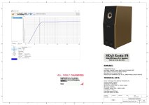
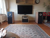
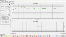
This is the system response in my room, average of 18 positions, mostly near the listening spot, with the EQ that sounds right after much tweaking:

shaded12_18_positions_avg.png

As you can see they deliver 35Hz-25KHZ. Of course at listener position in a real room, you want about 10dB more bass and that's exactly the case here.

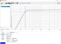
Phase response is essentially flat above 80Hz:

shaded12_24positions_phase.png

Most speakers butcher Impulse Response. Not these:
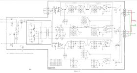
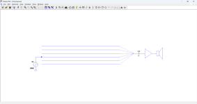
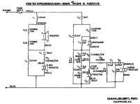
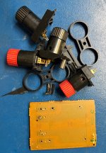
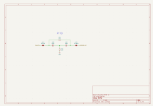
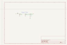
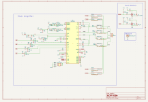
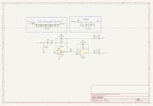
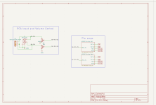
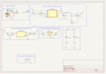
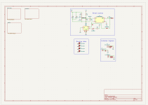
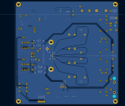
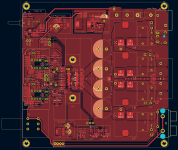
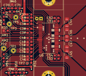
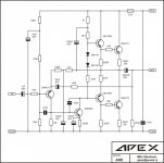
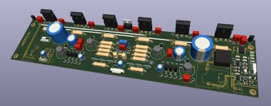
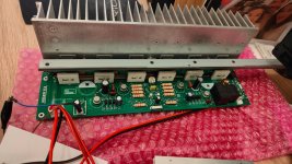
shaded_12_impulse_after4800.png


Schematic:

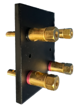
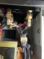
This design requires an elaborate filtering network to provide each individual driver with the exactly correct drive signal according to Keel's Shaded Array methodology. Each driver has a Zobel network (6ohms + 13uF) which flattens the impedance and makes behavior more managable.

The wiring consists of three parallel sections of four drivers wired in series. Each driver starting with driver #4 and above also has an RC network which directs extra high frequency energy towards the bottom drivers and less HF energy to the top drivers.

shaded array vituixcad schematic and drive signals.png


As you can see, drivers 1, 2 and 3 get 3dB extra signal above 1KHz, and drivers 10, 11 and 12 get 10-15dB less signal above 1KHz, with the intermediate drivers getting exactly proportional signals. I am very proud of the above family of curves.

shaded12_minidsp_eq_1jul2017+.png


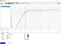
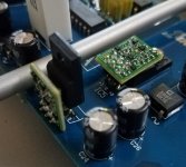
I used a MiniDSP 2x4HD to EQ these speakers flat. Above is the correction curve, which is absolutely necessary because without EQ the 3.5” drivers start rolling off below 150Hz.

The total system has roughly the same output capability of a quality 10” woofer in a bass reflex enclosure. The DSP boosts the signal the the 43Hz reflex tuning frequency and rolls off quickly below that, adding 6-10dB additional headroom at low frequencies. This is a critical aspect of the design, as a 6-10dB gain in LF dynamic range is not trivial.

I discuss this DSP technique in my AudioXpress article “The DSP Assisted Reflex.”

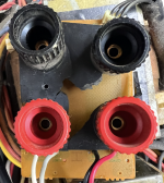
Port & Tuning Details

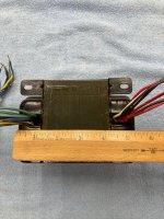
I used a flared 3” Precision Port from Parts Express. It is about 12” long and it tunes the 30 liter / 1.2 cubic foot box to 43Hz. The system cuts off sharply below 35Hz via DSP. These twelve drivers in a super-low-tuned reflex enclosure and DSP can collectively generate a lot of output, very similar strategy to the Bose 901 (which is an ingenious engineering design as I discuss in an AudioXpress sidebar, regardless of what opinions many audiophiles have about the execution.)

High Sensitivity

The midband SPL of these speakers is about 96dB. They have 14dB of boost at 43Hz and a similar amount of boost above 5KHz. Effectively they operate on average like a system with ~91dB sensitivity. Pretty efficient overall. The high efficiency adds to the slam and dynamic range.

These sound great and play quite loud with small low power tube amps.

Impedance

shaded_array_measured_impedance.png


They are easy for any amp to drive. You can see in this graph the port tuning frequency of 43Hz and the impedance is around 10 ohms at low frequencies and 4 ohms at high frequencies. These speakers are easy to drive.
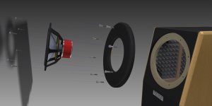
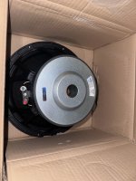
Driver Choice
shaded_array_fountekFE85.JPG


The Fountek FE85 is an excellent full range driver. It has a 3/4” voice coil and very light cone assembly of less than 2 grams. It has a fabric surround which ideally matches the acoustic impedance of the aluminum cone and very smooth response. It has very good high frequency resolution, as good as many dome tweeters.

Individually they handle about 10 watts RMS, so with 12 units per channel and equal power distribution at low frequencies, this system has no problem putting out 110dB+ SPLs in a real room.

Fortunately the FE85 is still available. Plus many great alternative choices are available from Dayton, Tang Band, FaitalPro and many others. As long as you choose an 8 ohm unit, you won’t need to change any of the Shaded Array filter network values. However your DSP EQ will change and anyone with a DSP and a microphone can easily pull that off.

There is no need for FIR (Finite Impulse Response) filters as everything is very well behaved and there are no phase errors that you can’t correct with standard IIR (Infinite Impulse Response) DSP filters.
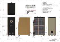
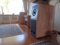
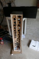
Cabinet details

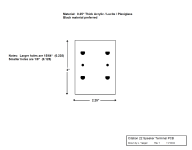
The cabinets are 46” high, 7” wide and 14.75” deep. These are the sketches I gave to my carpenter Joseph Budka, who milled these on a CNC machine:

shaded_array_7822.JPG


shaded_array_5311.JPG


The drawing below shows the coordinates of each facing surface on the side panel that touches the front panel pieces, along with the angles of each facing surface.
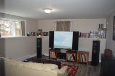
shaded_array_6807.JPG


shaded_array_half_built.JPG


How do they sound?

The stereo image is deep. The apparent sound source is about 2-3 feet behind the speakers, just as Don Keele’s Constant Beamwidth Transducer model predicts.

I’ve built LOTS of different designs, you can search my screen name on this forum to find more. These are one of the better systems I’ve made, successfully squeezing a great deal of performance out of 3.5” full range speakers.

Resolution is high definition and extremely detailed. The aluminum cones have a slight edge and if your amp is harsh or sounds grainy, that will come through.

“Shaking the house” and full range drivers don’t usually go together in the same sentence, but these deliver. They have a LOT more dynamic range than 99% of full range designs. The DSP Assisted Reflex means that even with songs like “Russia on Ice” by Porcupine Tree, which has a loud 34Hz pant leg flapping synthesizer late in the track, these have no problem shaking the house.

If I were to build these again, I would consider a more expensive high end driver with underhung voice coil. I would be tempted to choose a paper cone instead of aluminum, as the metal cones have a slight edge that can come off hard at times. The Dayton PS95 is a very good choice.

I would also consider an even larger array, using 16 or 18 drivers instead of 12.

VituixCad and MiniDSP 2x4HD files are attached in Zip files.

shaded_array_parts_express.JPG

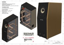
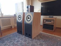
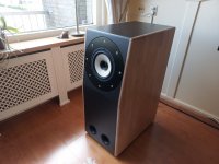
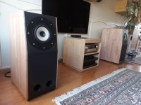
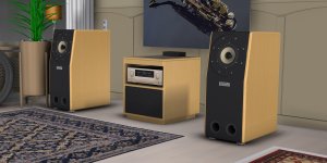
I wrapped them 360 degrees with black grille cloth with an oak wood cap on the top. I used very dark wood stain that makes it almost black.

I took these to the Parts Express 2017 speaker design competition where I got a lot of questions from curious designers. (Coincidentally, the speaker that won the competition was a much more sophisticated 2-way Shaded Array design.)

I think shaded arrays are underrated and I encourage y'all to try a design for yourself!

Attachments

Dayton Audio RSS315HF-4 Vented Enclosure - Critique?

I've just finished modelling and drawing up a vented enclosure for the Dayton Audio RSS315HF-4 12" Subwoofer.

Can anyone give me a critique on the design or see if I've made any errors?

I've modelled it as an 80L vented enclosure, tuned to 24.35 Hz with a 200w input signal. The amp is a 500w BASH plate amp. I'll set the HPF to 20 Hz.

I've read in some forum that the driver displacement is 3.8 L but no idea if this is correct.

Any input would be greatly appreciated.

Parameters as follows:

Impedance 4 ohms
Fs 24.2 Hz
Re 3.1 ohms
Le 0.96 mH
Qms 2.83
Qes 0.45
Qts 0.39
Vas 84.1 liters
Cms 0.23 mm/N
BL 13.99 Tm
Mms 188g
Xmax 14.3 mm
Sd 514.7 cm²
Vd 736.0 cm³


1000022943.jpg
1000022928.jpg
1000022926.jpg
1000022925.jpg
  • Like
Reactions: stv

D4K5 DIY Class D Amplifier 2000W ( Gerber Files) - working PCB or fake ?

Hello Friends


D4K5 Class D amplifier (about 2000W 4 Ohm)

Fake or working PCB and working circuit ?

Does someebody here build this D4K5 class D amplifier ?


I have download from elcircuit.com schematic, Gerber Files, Youtube Video

High Power Class-D Amplifier D4K5 - Electronic Circuit


This amp design have 3 Mosfets and should work from +/- 30 to 100 V Rail

in Youtube Video everything look fine but some people writing in Blog PCB dont work, you will waste money

The Minimum, to Use Opamp as Input in Power Amp

What’s the minimum requirement to use opamp as the input stage of the power amplifier? It might be:
1, Good voltage swing, as the power rail voltage is often limited.
2, A bias network that could provide a fixed voltage for the output stage.

Here we go.
1732102917285.png

The bias network is bootstrapped, so you loose little to none voltage swing. The output stage could be mosfet or EF2, etc. Change the resistors from the bias network to fit your need.
  • Like
Reactions: lineup

TU-8500 with Sparkos Labs Discreet Voltages Regulators

I was talking to one of my good friends recently, and when we got on the subject of our current audio projects he told me how he had significantly lowered the noise in his diy phono amp by switching over to discreet voltage regulators. specifically, regulators made by Sparkos Labs.

This got me thinking about my TU-8500, The Phono section is probably one of the quietest I've ever heard, Especially with some Burr Brown OP AMP, This gear is just spectacular. Even with my HD800's can I barely hear the Phono hiss.

When I switched to an ART-7 MC pickup last year I finally got to make use of my AT-1000T SUT (only 1,000 were ever made). But even with this SUT, the gain was just half of my previous pickup, a VM750SH MM, who's output sits at 4.0mV. The ART-7 in the other hand has a super low output at 0.12mV (2.2mV with loss after the SUT).

This required a bit more gain from the TU-8500, but even with the knob turned up a bit more. the phono hiss, although a bit more audible, still sat very low. and after the conversation with my friend I decided to order two discreet Voltage regulators from Sparkos Labs, a +12V regulator and a -12V regulator.

I just got them in today, and honestly I wasn't expecting any audible differences, they are only voltage regulators after all. I carefully removed the original LM2940C, and LM2990 regulators. The Sparkos labs regulators, although bigger, fit perfectly on the board. After placing everything back together I did some voltage checks on the provided test points on the TU-8500, everything was more or less the same except the +12V and -12V points. With the original regulators +12 sat at 11.6V and -12 measured at -11.74. The Sparkos labs regulators+12, measured 12.0, right on the money! and -12 now at -11.98.

Again, when I got this back into my chain, I wasn't expecting anything, they are just voltage regulators, how much of a difference can they really make anyways to the over all sound? After flipping the switch and putting on my HD800 over my ears I stood there waiting for the 8500 to power on, just watching the blue LED blink on and off until it finally just stayed solid.. And what I heard next was nothing.. I looked at the amp, and made sure I had adjusted the volume pot to my marked sweet spot, that I had it set to 3x gain, and that I had set the input to phono, everything was correct. And still, I heard nothing. normally I would hear a faint hiss.

I don't have the gear to measure noise or anything like that but my ears. The phono hiss is gone at the same volume setting and 3x gain. As Im writing this im Listing to Max Richter's "The Blue Notebook, and it sounds just a little bit louder than before. I normally have the volume knob at 12 O clock on my TU-8600, I've had to back down a little bit.

I decided to figure out what happened to the hiss. without a scope on hand I'll have to use my ears. With the stock regulators my Volume knob on the 8500 was set to about 2 O-clock, this was the ideal spot, just a little hiss but enough gain. With the Sparkos Labs regulators, I can push the knob to about 3:00 and I can start to hear the faintest of hiss, moving on to 4 o clock and I can hear the same amount of hiss that I did before on the stock regulators.

With the Sparkos labs regulators I can get more gain with far less noise trade off. I don't know why, I really wish I had a scope. As far as sound stage goes I hear no difference through my KEF R300, or HD800.. The only difference I hear is noise. Maybe the Sparkos regulators provide a cleaner power source for the phono section of the TU-8500. It would be worth looking into for those with a scope!

Attachments

  • Screenshot_20200415-014421_Gallery.jpg
    Screenshot_20200415-014421_Gallery.jpg
    781.2 KB · Views: 660
  • Like
Reactions: raoultrifan

Citation 22 / 24 Speaker Terminal Fix

A client brought in a Citation 22 beast for repair. I replaced a complimentary pair of output transistors to get it working. However, the OEM speaker terminals were also smashed in.

I don't know why the folks at Citation decided on such a crappy way to connect speakers, using very weird terminal hardware that appears to be not only a PITA to connect, but also a weak point – they break fairly often (enough so a European company sells a ready-made solution). Apparently this design is also common to the Citation 24.

I considered the European fix but didn't much care for their terminals. So I had a local trophy shop laser-cut a 1/4 slab of dark Lucite™. The laser made it possible to key the terminals so they can't rotate.

Here's some pics.

Attachments

  • Citation 22 broken.png
    Citation 22 broken.png
    440.6 KB · Views: 46
  • Citation 2 broken pieces.jpeg
    Citation 2 broken pieces.jpeg
    1.2 MB · Views: 36
  • Cit 22 terminal backplane.png
    Cit 22 terminal backplane.png
    126.8 KB · Views: 42
  • Cit 22 Replacement Panel.png
    Cit 22 Replacement Panel.png
    2.4 MB · Views: 39
  • Cit 22 fix interior.jpeg
    Cit 22 fix interior.jpeg
    597.3 KB · Views: 42
  • Cit 22 fix exterior.jpeg
    Cit 22 fix exterior.jpeg
    372.9 KB · Views: 39

Adding a driver?

Hello all,

I currently have a set of speaker towers i built off a design I found online. After seeing some of the posts here about it, it's not a well favored design. But frankly I enjoy it. I've had these towers built for awhile now, and at this point I've had the itch to mess with them again. They are currently an MTMW design and I wondered how much would need to change in the crossover to make it a MTMWW design?

Remote motorized volume control / 4-input relay switch: source code for STC89C52RC microcontroller

I recently bought a passive preamp from AliExpress. It is nicely made, with a motorized potentiometer and 4 relays to select and input. There is also an on-board relay to power on/off other devices, though that is not currently attached.

The IR signal from the remote control is decoded and the motor and relays are controlled via a 40-pin STC89C52RC 8-bit 8051-style microcontroller. I'd like to modify that code so that the preamp responds correctly to several different remote controls. Does anyone know if there is source code available for this on GitHub or similar?

Artistry vs. engineering, or: Are we just nuts?

It's half past three in the morning here and I'm in my hobby room, enjoying some very non audiophile-approved music on my recently finished transmitter triode DHT SET.
To produce 2*5 quite decent sounding watts I've bought Soviet made input tubes from Ukraine and French driver tubes. The output tubes were made in USA some 80 years ago by Taylor and imported, via eBay, to Sweden by me, one by one in unknown condition and at horrible shipping costs.
The mains transformer, OPTs and driver stage cathode chokes were bought from Italy, then there are several other smaller transformers and chokes from different manufacturers.
In the context of DHT SETs this is a budget amp, still I could easily have bought a decently functioning car for the same money.
Looking at only the specs, the little critter between my thumb and index finger in the picture eats this amp for breakfast at perhaps 1/1000th of the cost.
sandvssand.jpg


This is the Tube forum so I can't be the only one with this...perverted mindset.
Some may say tubes sound better. Ok, except that they don't, not necessarily. Properly designed SS amps can sound just as good as any tube amp.
My theory boils down to one thing: The glow. Inherited memories cavemen staring into camp fires or something, I don't know.
End of rant, feel free to share your opinions!

After a Diligent Search for a One-Box Electronics Solution... the winner is...

nad-m10-v3-top.jpg

I was helping a friend (who had just taken delivery of a pair of custom Purifi/Beyma AMT 2-way monitors) winnow down the electronics options, with a preference for One-Box solutions.

About that, my overall observation is that GaN Modules, as well as Switching Amp PCBs from Hypex and Purifi, have been major Game Changers in High-End Audio.

HiFi Rose's GaN-based RA280, which is not a one-box solution--it is an Integrated Amplifier with no Digital Inputs--has a rated output of 250 Watts per channel. It's a sleek item you could tuck under your arm (16.9 inches wide, four inches tall, and 14 inches deep).

But I can remember when it took two strong guys to lift Plinius's 250Wpc stereo amp. I'd call that "Changing the Game."

So, my friend narrowed his search down to NAD's offerings. The M33, with the Purifi power-amplifier module, was too much money (5K). I loved the NAD 3050's Retro styling, as well as its knobs and switches! But he did not. And, the NAD dealer said that the core amp in the M10 (the V2 has a Hypex Hybrid Digital nCore Amplifier) was better than the one is the 3050. BTW, the V2 is rated at 100Wpc while the V3 is rated at 160Wpc. (The V3 is also powered by Hypex.)

When the dust had settled, my friend had gotten a bargain close-out price on NAD's M10 V2, which is being sold off to make way for the M10 V3. What he loses out on, by not waiting for the V3 (and, paying about $1000 more), apart from 60W more power, is a built-in MM phono stage. So he will have to pick up an affordable wall-wart phono stage.

I've never had a piece of audio gear with a touchscreen, but perhaps I could get used to it.

BTW, Siri is on the outs with me, ever since I said "Open the Pod Bay Doors, Siri."

In a VERY hurt tone of voice, Siri replied, "That's a terrible thing to say to a Sentient Entity." I apologized.

And then, to try to make it up to her, I asked her if she had any plans for dinner. She hung up on me.

So, "Siri, please choose the best recording of Beethoven's Op. 127" is most likely not in my future.

Back to the NAD M10: What excites me about that choice is that for $100 you can activate the included DIRAC Room Correction. If it's good enough for John Atkinson, it's good enough for my friend.

Here's a link to Future Audiophile's news item on the upgrade from M10 V2 to V3.

I hope this helps anyone who is still In the Hunt.

john

Yet another TPA3255 PFFB amplifier - Review request

I have worked on TPA3255 based BTL amplifier for a while now. As this is my first time attempting to layout a class D amplifier I would appreciate some feedback.
I have tried to follow the layout and schematic from the EVM, the feedback given in other threads on here, as well as SLAA788A for the PFFB, but I have probably missed something.
The layout is done on a two layer PCB and I will get all the SMD components assembled by the PCB manufacturer.
The VIA stitching is not done yet, so that is missing. The connectors I have mainly chosen for easy testing.
I have attached both schematics and PCB screenshots here, as well as a PDF of the schematic.
Thanks in advance!

Attachments

  • side_3d.png
    side_3d.png
    150.4 KB · Views: 285
  • top_32_no_pth.png
    top_32_no_pth.png
    144.1 KB · Views: 276
  • top_3d.png
    top_3d.png
    154.9 KB · Views: 256
  • TPA3255_pffb_amp.pdf
    TPA3255_pffb_amp.pdf
    855 KB · Views: 205
  • pffb.png
    pffb.png
    13.7 KB · Views: 240
  • output_filter.png
    output_filter.png
    15.5 KB · Views: 236
  • main_tpa3255.png
    main_tpa3255.png
    54.1 KB · Views: 231
  • preamplifier.png
    preamplifier.png
    26.1 KB · Views: 227
  • inputs.png
    inputs.png
    29.3 KB · Views: 216
  • power_supply.png
    power_supply.png
    41.6 KB · Views: 206
  • overall.png
    overall.png
    27.2 KB · Views: 230
  • rear_copper.png
    rear_copper.png
    66.9 KB · Views: 232
  • front_copper.png
    front_copper.png
    147.2 KB · Views: 228
  • tpa3255_closeup.png
    tpa3255_closeup.png
    122.2 KB · Views: 249
  • Like
Reactions: addysoftware

HornResp Question - S1 Visual vs Area

This may be obvious but I need someone to clarify if possible. Using a tool like HornResp, I'm trying to grasp how S1 (area of the entrypoint to a horn) relates to Sd (area of the speaker cone) when the two are different shapes.

Good example is an Altec 816, where the business end of the driver+horn looks like a sideways Underground sign. Sd of a 15" driver is somewhere around 1000cm2. Drawings of the Altec 816 show that the rectangular horn entry S1 is 21"x8", so about 1084cm2, so pretty close in area. Except, visually there is some dead space for both components - part of the driver's Sd area is blocked behind the horn entry, and part of the horn's S1 area is made up of inert motorboard.

Does the shape of the horn entry and its relationship to the driver cone have any impact on the effective S1? The obvious answer seems to be no, but the configuration of the Altec 816 - where a meaningful amount of S1 area is some meaningful distance from the actual driver - has me doubting. Thanks in advance!

Aluminium hybrid polymer caps okay for audio?

Hi

I know that electrolytic caps have about the worst characteristics for audio - especially in series with the signal - but...

I see highly respected manufacturers using what look like electros as coupling caps between gain blocks. Are these caps possibly the hybrid polymer types instead of straight electrolytics? I friend found that the leakage through the polymer caps was low enough he could use them in series with a feedback gain control since he did not have space for an equal value of plastic cap.

In any case, has anyone tested the hybrid polymers for audio?

I was puzzled when I did a circuit sim and the THD20 was lower than the THD1. Then I increased the value of the input coupling cap and it was much better. However, I had to make a fairly massive increase which makes using polypropylene (preferred) a lot more space consuming.

Thanks for any advice

can I use any 600ohm (impedance) 1:1 line input transformer for input isolation?

as above.

What specs should I be looking for?

As an example, I looked at these 3 transformers
Thanks

USB audio interface (in/out) which sounds good too

Hello,
It is time again for me to buy a new PC audio interface. Not my main source, but sometime I listen to music from my t.c. electronic Konnekt 8, which has a pretty good DAC + a Bottlehead Crack + HD800S.
Now, the firewire interface is more and more problematic, I want to get something else again. Not long time ago, I've bought a Focusrite 2i2, but my daughter needed it (playing classic guitar etc.). The Konnekt 8 with the Crack is pretty good to listen to, the Focusrite is not, but that is better for ADC. So now again I try to find what in/out interface to get (in is needed, I record live sometime).
I find several sources for specs like S/N ratio, but I find no reliable source which sounds better.
Do you guys have experience with these? Can you recommend other info source? A forum, FB group etc.?
Thanks!!
JG

Relay control?

The relay, RL1, in my Citation 25 has an erratic function as it doesn't always close (click) when changing programs and if I don't make sure it clicks (closes) through quick program changes before shutdown then DC leaks to the output stage which makes it "pop" " in the speakers.
It seems that the control current to the relay is not sufficient? Which component(s) could be to blame for this?
RL1 Not properly functional.JPG

Accuphase C200 Recap Question

Hey all! I’m recapping my C200 that I acquired a couple of weeks ago. These boards are a pain to desolder components from, time consuming for sure. I’ve replaced half of all electrolytics as of today. Anyways, somebody has worked on it before me, fairly shoddy job. The PSU board has some components replaced with lifted pads as a result. See the absent solder pads on C5. C7 has also been replaced with a crappy brand of capacitor so that’s going out. Since the ”tech” that worked on this before doesn’t seem to have had a clue of what he was doing I got worried about the orientation of the cap. From what I’ve seen in various recap threads, and reading the schematic, the caps negative is supposed to go to anode on D7, and positive to cathode. Is that correct? It still works fine with the cap in this orientation, but I want to make it proper. For you people that knows more than me about schematics, what would the consequence be of having this cap in the wrong orientation? Could it have been installed with polarity reversed from factory by some reason? Thanks for any input!
IMG_3047.jpeg
IMG_3048.jpeg

A second trafo for YBA Delta 3 power amp

Hello, I have a beatiful YBA Delta 3 power amp:
2024-05-04 at 13.05.38.jpg
and I'd want to add a second trafo to obtain a HC-DT version, more stable and agile with my 3-4 ohms Thiel CS2.4. Somebody gave me a trafo which seems identical in dimensions and weight to the factory one but measuring its ouput it has a +1.2 volt higher voltage per winding than the factory one, and wiring it using the paralleled windings per branch, I obtain a wonderful result in terms of current but a very light 50 hz buzz at speakers, probably due to the slight asimmetry of the two branches.
My question is:
  • does somebody knows the specs of the factory trafo, in terms of Volt and Amperes?
  • is it still possible to find in commerce any of that, so I can find a paired couple?
  • is there any more modern suitable trafo (not toroidal in respect of Yves Bernard Andre ideas), such as R-core, even with higher current, I can use, paired, instead?
Many thanks to all.

Streamlining speaker driver frequency measurements

I would like to pose a question: "How are people measuring frequency response on drivers that have no documentation?" I highlight the question because there doesn't seem to be information about a system or quantified Equipment that one can take and produce frequency graphs. As Anachoic Chambers are out of the question, the following are what I have Same, heard or read about in terms of getting measurements
I read that people use a closed box for frequency measurements, I do not seem to get a feel for how big the boxes should be in relation to speaker size and type and whether to flush mount or surface mount To this closed box.
Large flat baffles, where the speaker is placed within the baffle, seem to have their own quirks which do not get described very often. I remember an article written by Zaph. (No longer writing?), Explaining some of the requirements that had to be added to the baffle sheet, To be able to get results, But this to me seemed incomplete.
I note a device that possibly changes the landscape Of driver frequency measurement called the tetrahedral test chamber by Geoff Hill. It seems like a great idea, put it in a corner, possibly Assemble and disassemble so it doesn't take up space, but there are probably requirements there that may be beyond the DIYer To execute, in order to be able to get good results.
So, how does one measure the frequency response on drivers?

For Sale Dario Miniwatt R120 tubes

Selling 1x pair of Dario Miniwatt R120 tubes

These are great sounding IDHT tubes, often referred to as the European 2A3.
For those interested, you can build this excellent R120 amp by Pete Millett : http://www.pmillett.com/r120_se_amp.html

They measure 64ma and 67ma, where 60ma is nos

SOLD

Attachments

  • tempImageqcXl6v.gif
    tempImageqcXl6v.gif
    1.9 MB · Views: 97
  • tempImageSzGVUr.gif
    tempImageSzGVUr.gif
    1.7 MB · Views: 91

Unison Research Triode 25

Dear members!
I have an Unison Research Triode 25 EL34 Amplifier in use.
Last day, during tube rolling (I changed from EL34 to 6CA7) by a matched Quartett I blew one of the fuses, (in one channel) which I want to replace.
It´s those 5x20mm type and I assume (it says 500/250V), it´s 500mA.
Anyway, could I be right with my assumption as well as, is somebody owning a service manual or at least schematic of this amp?
I once had an issue with this amp, the manufacturer sits in Italy and is not very responsive. The German distributor either.

I believe, that one of the tubes was defect (although I used it well before in another amp). I never had this experience with tube rolling, can tubes break that easy? No idea, that´s strange to me....
Thanks in advance and best regards
Hans

how hard would it be to make a simple S/PDIF, coax DAC with the TDA1545

found an old sony mini system in the bin and in it there was this tda1545 ic(along other usefull components) and im wondering how hard would it be to make a simple spdif/coax dac for my tv(that lacks an anlog output) or a crappy dvd player.
IMG_1097.jpeg

i also professionaly soldered one of the legs back on. it works but it looks a bit ugly.

Suitable Horn Flare for 18sound NSD1095N + Beyma 12P80NDv2

I am working on a draft brief for a three way system using BMS 18N862-8 Ohm, 18" bass driver a 12" Beyma 12P80ND? or V2 as it is now as the former is no longer made? and a 18sound NSD1095N which is an excellent driver as I have used it before.

I am looking for opinions for a suitable Horn Flare to work and integrate with the 12" Beyma (or other suitable 12" unit)

My initial thoughts were to use a Beyma TD164 which has Coverage angles of 60º in the horizontal plane and 40º in the vertical plane, is this a good match for the dispersion of the 12" driver?

Crossover has not been set but likely around 200Hz / 1300Hz or so.

Thanks

DM 🙂

Help measure drivers on baffle with REW and USB Microphone, Make FRD & ZMA

Hi all,

I recently built a baffle and put some drivers in it and was happy with the physical result. I had boomarked some information on how to best measure them on the baffle and produce FRD and ZMA and all the links are either dead or the software is dead and I can't follow a tutorial, etc, because of the project being dead. So I'm back to square one. I realize this is probably simple, but I'm just running into a few issues that I can't seem to break through, so any brain-orientating-help is appreciated as I bone-head through this.

Equipment I have:

MiniDSP Umik-1 microphone (USB)
Dayton UMM-6 microphone (USB)
Dayton DATS V3

USB DAC, Amplifier, etc

Software:

REW
Xim
VituixCAD2

I went back over some notes and some information from others but I ran into some questions and confused myself.

My primary goal:

Measure drivers installed in a baffle I already made and produce FRD and ZMA files from my measurements so that I can work on passive crossovers in software (Xsim & VitruixCad2).

So, that requires that I make pretty good measurements in the first place. And this is my primary hang up.

I know I can make impedance measurements with the DATS V3 in the baffle and produce the ZMA file directly from that without anything extra (I think?). I'm not sure if there's anything else I need to know about or do to the impedance sweep from DATS before using it as a ZMA for crossover building.

Some of my notes:

1 - Driver in the baffle. Microphone centered up on the driver at a distance of 0.5 meters. Reference 1khz sinewave and use voltmeter to get 2V AC at the speaker terminal. Do this with >1m in all directions free of boundaries, etc. Take measurement.

2 - Next driver, same as above.

3 - Now, interferometry. I read about this but couldn't find better (simple) details for me to follow. But basically wire the two drivers in parallel and measure this as well. But, I'm not sure how to set that up properly and what to do with the result. For example, do I wire the tweeter and woofer together in parallel and then place the microphone centered between the two of them at 0.5m distance and do the same 1khz sine wave at 2V AC again? Or is that incorrect? I'm lost on what to do with this 3rd measurement. Measurement 1 is tweeter. Measurement 2 is woofer. Measurement 3 is both of them in parallel? I'm not sure what to do with that part (3). I read something about calibrating the microphone with a separate SPL meter and I'm lost on that part.

4 - In addition to the above, what about if I have 2 woofers and 1 tweeter? How does that change this for measuring the woofer(s) and for the (3) measurement with the tweeter+woofers in parallel?

5 - Any considerations on things if the baffle has a port like bass reflex when producing the response (separate measurements and sum the port plus the woofer)?

6 - Scale this to 1.0m distance and 2.83V. I think I can do this in REW easily (any notes?).

7 - If I use DATS to measure each driver in the baffle, do I have to do anything specific to the results to normalize or scale it, or is it good to go as a ZMA from just that measurement? If the impedance sweep involves a bass reflex cabinet, does this change anything with the ZMA file and do I need to do anything to it?


Thanks for reading and any comments to help out! I appreciate all of your time.

++++++++++++++++++++++++++++++++++++++

Here's the baffles and drivers I made that I'm trying to measure and build the crossover for:

DSCF1475.jpg


DSCF1474.jpg


20241107_135302.jpg


Current 1 meter response with active crossover (DSP). I want to do similar with passive crossover, so I'm trying to re-learn how to properly measure and produce FRD and ZMA so I can start working on that.

BG20 and 8PT WAW Open Baffle Active DSP 01 (Scale 5db).jpg


Very best,

Troubleshooting Onkyo SR508 with a shorted channel

Hi guys,
I was working on this Onkyo SR508 with the left channel shorted. One of the power NPN transistor had shorted out and one half of the noble resistor was also open.
So I took the two power transistors and the noble resistor from a working channel that is not used. Amp was working perfectly when I tested it. I should ask is it ok to leave the unused channel without the two transistors and the resistor?
Ran it for sometime I heard a relay click not sure which one it was - no error message nothing and the amp kept on working. Turned off and on again no problem, was working. The relay clicks after couple of minutes of use. I ordered the power transistors needed and took the amp back to the owner’s place to be used for the time being.
I wanted to check whether the speakers had shorted as this was my suspicion for the original failure. The speakers were fine.
The owner was using it for sometime and he called me back saying the amp had died again.
I went back the following day to have a look. Left channel had shorted out again. This time the two power transistor that I had borrowed from the working channel had shorted out. The noble resistor seems to be intact this time. In hindsight I should have borrowed the drive transistors from the working channel, damn! However the drive transistors still measure ok even now. Another thing I would like to remark is that the power transistors base has shorted to collector and emitter (could this be a clue). The fuses on the B+ voltage has blown as well. I would have to bring it back to my place to further investigate. I was wondering if you all had any suggestion on what to look for and any common failure points I should check.

Further points/questions I have:
1. What causes the B+ voltage to change? In other words what should cause the SEC1H signal to go high turning on the relay which changes the B+ voltage. (What is SEC1H?-the SM does not explain this).
2. Could that be the relay I heard while I was testing it?
3. Could there be an issue in the temperature detection circuitry? I noticed that the big heat sink get quite hot even with no signal applied. (Not sure how hot it should get). I did follow measuring the idling current procedure mentioned in the service manual. It remains with in specs. Also the thermal paste has become crusty.
4. I am having a hard time finding the noble resistor, I need a 0.22 ohm 2W resistor - but apparently they are almost impossible to source according to some forums. I came across 5W ones could I use them instead? Do they have a ‘fusible’ purpose in the circuit?
5. I noticed on one of the channel (working channel) the noble resistor was touching one of the driver transistor and the resistors body has got some charring. Could this be an issue?
6. Also noticed some of the capacitors looked a bit dark not sure if its suppose to be like that.(not the electrolytic ones).
7. Why didn’t the amp go into protection mode instead of blowing the fuses?

Any further troubleshooting tips advice would be greatly appreciated.
Thanks in advance.

P.S I tried uploading some pictures and Pdf of the schematic for some reason it doesn't seem to go through. So here they are uploaded to a flickr album Onkyo SR508 | Flickr

Hello forum members

My name is Sergey and I am from Russia. Please excuse me if the text seems illiterate, as I use a translator.
I create music as a musician, sound engineer and arranger. The projects are non-commercial and do not bring profit. But I like the sound, and I am happy with what I have. I also work on FM radio.

Homemade, repair and soldering are more of a necessity than a hobby. Workshops are far away and I can’t pay for them, so I do everything myself. But I can do a wide range of work and I try to enjoy it.

I am currently trying to repair my Event Opal studio monitor and only here I found a topic with active discussion.

Thank you for your time and have a nice day.

My new amp oscillate :/

Hello guys,

I need your help, my actual plan is to build an old amplifier that he was very appreciate in the 95's !
You can find the article here :
https://amplifredy.wordpress.com/2009/02/08/amplificateur-hexo-iii-the-hexorciste-is-rising-again/
There is a link for download the complete file.

I have made my own PCB, because he must enter in my case (the original PCB is too big).

The PCB was produced and assembled recently, and I started the first tests this week.. Unfortunately, the amp oscillate strongly, to around 250Khz.
I respected all values indicated in the project, the only difference are the output transistor, that I replaced from IRF630 to IRFP240 and IRF9630 to IRP9240.

I tried to add a 120p to the input (C26), and a Zobel filter, but same way (and the filter don't like the oscillating honestly xD)

The author indicate that it is prohibited to put a scope to the S and G of the Hex, because the amplifier enter in oscillating in this case. OK, but how can I check this problem ?

Below my PCB. All grounds are respected, of course.

Bias works, he can be modified. 0.2A minimum without load (it should be around 90mA with the actual PSU, with 2x63V... Difference should be due to the oscillating)

Help please 🙂

Attachments

  • Clipboard02.jpg
    Clipboard02.jpg
    327.1 KB · Views: 134
  • Clipboard03.jpg
    Clipboard03.jpg
    188.6 KB · Views: 131
  • IMG20241117190118.jpg
    IMG20241117190118.jpg
    449 KB · Views: 133

Micromega Solo CD Player - help!!

I have a Micromega Solo CD player which is not working. When turned on, it will start to rotate counter clockwise at first hesitantly and then faster. It happens with the lid open or closed ( a top loader) and also with a CD in place

I noted there is some slight vertical movement in the lens when it is turned on - but I cannot see the normal red glow on the laser when viewed from the side. Sometimes the laser assembly swings back and forth with CD in place.

I have noticed there is about 2-3 mm of vertical play in the spindle

It has a CDM4/25 transport fitted - I have tried cleaning the lens and checking all of the contacts. The 33uf cap on the servo board has been replaced - still it runs backwards!


I would greatly appreciate and advice and suggestions for sorting it out!

Regards Dave

Schematic for this beautiful Micromega Solo, Trio and CD f1 (first edition) wanted

I need a schematic diagram of this compact disc player models in top loader version
for attachment 4, 5 and 6 in high resolution open this URL:
Mcintosh MA6400 ????, MicroMega Trio CDP ??? ?????(Wilson Audio),????(Wharfedale),???(MARANTZ),??(JAMO),??(ONKYO),??(TEAC),????(JBL),?????(AUDIOPRO),??(KEF),????,????(Nakamichi),???(Philips),??(ARCAM),

Attachments

  • Micromega Solo IV.jpg
    Micromega Solo IV.jpg
    46.7 KB · Views: 1,385
  • Micromega Solo I.jpg
    Micromega Solo I.jpg
    249.9 KB · Views: 1,217
  • micromega_solo open.jpg
    micromega_solo open.jpg
    178.1 KB · Views: 1,671
  • micromega-Trio front.jpg
    micromega-Trio front.jpg
    286.5 KB · Views: 1,209
  • micromega-Trio top.jpg
    micromega-Trio top.jpg
    286.5 KB · Views: 1,153
  • micromega-Trio rear.jpg
    micromega-Trio rear.jpg
    286.5 KB · Views: 541
  • Micromega CDF1.jpg
    Micromega CDF1.jpg
    132.5 KB · Views: 785

HUMM noise using a Toslink to analog converter

Hi everybody!
I'm using a Toslink to analog converter to connect the TV to my Luxman L3 amplifier:

image.jpeg


When I use other sources like CD players, I hear no humm or other kind of noise. Only when I select PHONO I can hear a small humm noise + a sharp sound, but just a little an it's not annoying.
But using this DAC I hear very annoying Humm noise + sharp sound.
Neither the TV nor the DAC have a ground connection.
Maybe connecting TV or DAC to ground can solve the problem? And if so, how can I ground the TV or DAC?

Thanks a lot.

Thielle-Small Theory Course and Optimization

Hello everyone,

I’m excited to share that I’ve launched a basic course on Thiele-Small Theory on YouTube! In this course, I dive into the mathematical modeling of a speaker inside a box, covering all the math behind it. I explain the equivalent circuits for different box types, starting with sealed enclosures and progressing through bass reflex, 4th order band-pass, and more.

So far, I’ve posted 4 videos, and there’s much more to come. Each box design is modeled in MATLAB, and the results are compared with WinISD. In my latest video, I implemented a Particle Swarm Optimization (PSO) for the 4th order band-pass. In this example, I define target start and stop frequencies where I want the response to be as flat and loud (in terms of SPL) as possible. The PSO then optimizes the box’s rear and front volumes and the vent size to achieve the best results.

The ultimate goal is to use PSO to design an 8th order band-pass, and then build the enclosure for real-world validation.

While the videos are in Portuguese (since I’m Brazilian), there are plenty of equations and diagrams, so if you enable automatic subtitles, you should still be able to follow along.

You can find the course on my YouTube channel here: https://www.youtube.com/@insanity_bass

Thank you for your attention!
  • Like
Reactions: stv

Two new AKM DAC

AK4497S described as a 'reimagined' AK4497 :

and

AK4498EXVQ which seems to be the analog part of the AK4497 intended to work with a AK4491. A kind of lower spec AK4499
Both are in QFP package (HTQFP) thus DIY compatible !
  • Like
Reactions: mamocel and astx
Projects by fanatics, for fanatics
Get answers and advice for everyone wanting to learn the art of audio.
Join the Community
507,634
Members
7,881,168
Messages

Filter

Forum Statistics

Threads
405,908
Messages
7,881,168
Members
507,634
Latest member
kwong1