SissySIT

Opening new thread , to make things easier to follow and comment .

Everything started with collective brainstorming in Most Greedy Boy, of them all... or (there is no) DEFiSIT of Papa's Koans thread , and resulting prototype posted in #618 , Most Greedy Boy, of them all... or (there is no) DEFiSIT of Papa's Koans

Tnx to all Greedy Boyz involved ........

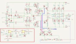
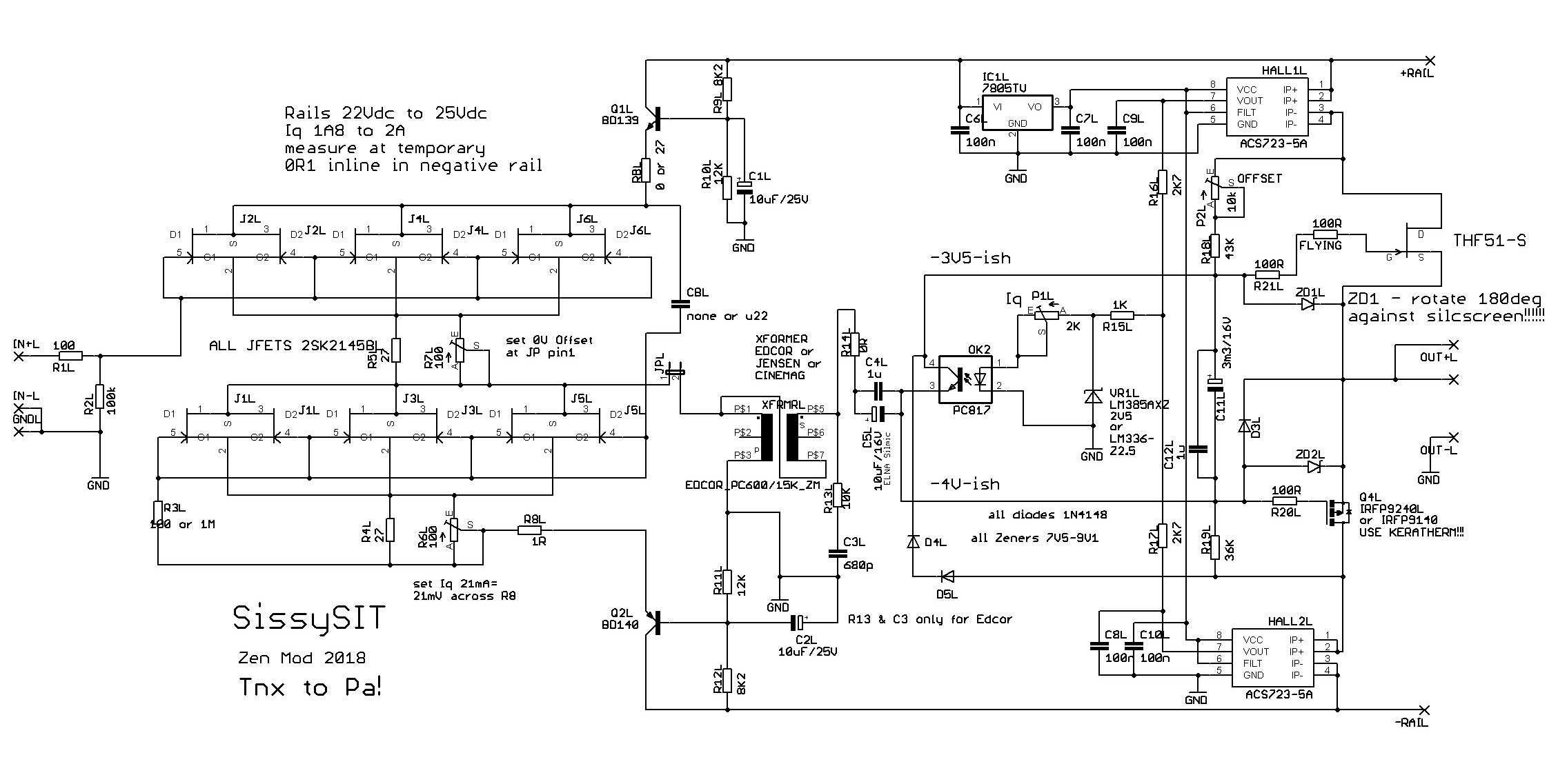
as I wrote , SissySIT ( in fist time called SUFI-SIT , but then I realized that too much seriousness is ..... too serious 🙂 ) is practically THF51-S Tokin SIT nested in Babelfish M25 circuit (even pcb) , with necessary change in some parts values .

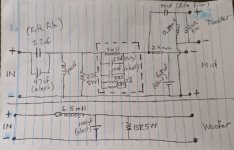
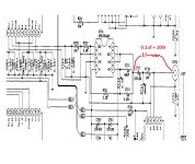
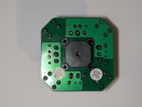
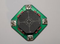
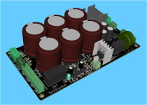
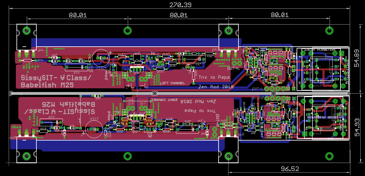
so , schm and last/final pcb iteration are these :

(observe that I finally decided to match my pcbs to DiyAudio UMS ...... taking in account Jason's and 6L6's stance - better keeping things less complicated , than asking for few more taps in existing UMS..... so , besides SissySIT being Sissy , ZM is Mighty Sissy , doing things to save Greedy Boyz from some drilling/tapping efforts)


699402d1535226175-sissysit-pcb-sshot-jpg


699403d1535226175-sissysit-schm-jpg

Simple 60dB discrete low noise amplifier (lna)

This subject started in another thread

Super Regulator, collecting the facts

but it seems a discussion on its own, so I moved it here. The idea is to build a low noise amplifier with 60dB (1000x) to use it as for noise measurements. Initially I built the circuit from the Linear Technology application note 83

http://cds.linear.com/docs/Application Note/an83f.pdf

but I wanted something with even lower noise so I put together a simple discrete circuit using paralleled jfets (2sk170v). However, I used no feedback so setting the gain to 60dB with low tolerance is something that relies on a very good AC voltmeter. Jan recommended using feedback to be able to calculate and implement the gain accurately. What comes next has been moved from the other thread.


This is what I built 🙁

The subtler issues escape me, as you can see.

Attachments

  • amp-ln-1e.png
    amp-ln-1e.png
    26.9 KB · Views: 3,986
  • amp-ln-1e-fr.png
    amp-ln-1e-fr.png
    10.2 KB · Views: 3,770

Yamaha P-2200 VU Meter 100% on Power on

Hi all,

I have a Yamaha P-2200 amp that's VU meters jump to, and remain at 100% when powered on.

The VU meters were working find before taking it in for a service, and to have the power supply changed from 100v to 240v.

After I received it back, the VU meters jump straight to 100%, and remain at 100% until powered off..

Any ideas on how to resolve would be appreciated!

Attachments

  • IMG_9062.jpeg
    IMG_9062.jpeg
    392.8 KB · Views: 113

Audio Innovations 500 output transformer

Audio Innovations 500 output transformer - Solved

Hi folks,

Hope that someone can poke me in the right direction - how to go about output transformer (replacement or rewind?).

My AI 500 is currently out of service, this is the model with 4 & 8 ohm taps - the 47R 11W (the one just after rectifier, between those two 220uF/400V caps) went up in smoke & fire. It literally burnt.
I naively thought (to be more exact i hoped) that this was down to its age/deterioration so bought some 10W47R from Maplin, soldered it in, switched it on, a pop in speakers and dead silence followed. No hum or anything, just pure Sound of Silence 🙄

To cut the story short - apparently left channel output transformer primary & secondary windings are shortcircuited, DMM shows 12 ohms between yellow wire (i assume B+ wire on in schematics) and any wire on the secondary side (blue, red or green)
It also seem to be circuit-open between yellow & green or blue on primary side.

The following are the readings should someone benefit from it or eventually advise if those are normal (sensible) values):
(-the color of wires matches schematics)

Left channel:
B+, green = 0 Ohm
B+, blue = 0 Ohm
B+ violet = 22.9 Ohm
B+,black = 55 Ohm
green, blue = 26.5 Ohm

Right channel:
B+, green = 20.1 Ohm
B+, blue = 46.7 Ohm
B+, violet = 22.5 Ohm
B+, black = 54.9 Ohm
green, blue = 26.1 Ohm

The broken transformer has resistance of 12 Ohm between B+ and minus/earth (blue wire on secondary winding)

The good one shows resistance of the values 0.550 MOhm between B+ and minus/earth (blue wire on secondary winding) although this number likes to go up to 0.8 - it actually fluctuates.

Can someone please advise:

1.) buying a replacement - where from?
2.) rewinding - where/what company does this & what
are the parameters/specification of this transformer or where to get these from?
3.)buying second hand if anyone happens to have one 😛

In case of buying a replacement, would it not be a better idea to replace also the working output transformer so that those two are similar in parameters?


No idea why this all happened but could it be that i had Xduoo x3 hooked to it via AUX therefore simply overloaded it?
By the way, when listening to the vynils - I could turn the volume pot to max and it would be loud.
When listening to CD, anything over 90 degree knob - the music was way too loud.

The rest of the components inside seem to be fine, no strange looking colors or burns, can supply photo if anyone needs it.
Also i believe that it is all still original components inside.

So i hope that there is a solution to my current misery 🙂
I can imagine this may to be quite costly repair,hope that it will turn to be some reasonable price.

Thanks for reading & help.

Attachments

Open Baffle project starting as a variant of Perry Marshall Cottonwoods--some help needed! :-)

In @perrymarshall's thread about his open baffle/bass reflex hybrid I accidentally hijacked it a bit, with Perry suggesting I consider his Cottonwood Live Edge Beryllium design with the drivers raised.

Funds are a little tight right now so I decided to attempt the build but with less expensive tweeters. I don't really know what I'm doing here yet, so thoughts are welcome!

Here's what I've cobbled together thus far:
  • a used miniDSP Flex 8 and Umik-1 microphone
  • a pair of SB 15OB350 woofers
  • a pair of SB26CDC tweeters, and working on getting a pair of 8" oval somasonus waveguides. I couldn't swing the TW29BWGN, but that or the TX could be future upgrades.
  • a pair of the PRV WG175PH horn tweeters Perry's used for multiple designs, for the back side of the baffle
  • passives to equal to the Live Edge Beryllium Cottonwood design (47 uf film caps for the front tweeter, exact cap and resistor values for the rear tweeter)
  • a 5-channel amp stolen from my HT system, to be replaced with Eric A's 2x150W amp modules in the near future
  • free 1.75" thick used doors to chop into test baffles. First thought is 15" woofer at 24" off the floor, slightly tapered toward the tweeter at the top, triangular wings for the woofer zone.
I'm not expecting this to be my end game forever system, but rather, a fun learning platform that hopefully sounds great as well. Over time I might add a mid-woofer and push the woofer to the floor, or try other things.

Now that I have the raw materials on hand I'm a bit lost on how to start getting this set up in the Flex 8.

Anything you could suggest to get me in the ballpark would be deeply appreciated!

Hafler DH-500/P500 Mods

Time to start this long over due thread
I just need to find one now 😛
Maybe the posters in the DH-200/220 Mod thread can use this thread instead for these models 😀
We are working on adapting the DH-220C design for use in DH-500 & P500 chassis
There are some new OPS boards in trial for those heatsinks.

Attachments

  • 1069690-hafler-dh-500-audio-power-amplifier-made-in-usa.jpg
    1069690-hafler-dh-500-audio-power-amplifier-made-in-usa.jpg
    130.1 KB · Views: 2,147
  • hafler-p500-power-amp_2.jpg
    hafler-p500-power-amp_2.jpg
    47.3 KB · Views: 1,724

How absolute is matching a CD exit angle to horn?

Hi All,

I'm picking up an old project. The previous owner stripped all the drivers from these horns, so I've been slowly regathering all the parts necessary to complete it.

The horn originally had an TAD 2001 installed on it, but a decade or so later, claimed these were NLA and told techs to replace with Celestion CDX1730. These two drivers have a different exit angles. 2001 has a reported angle of 8 degrees, where the CDX1730 has a 20.16 degree angle. How different will the end result be? Common sense is telling me just to go with the 1730, but I do prefer the BMS 4550 in general, or something newer from the 18Sound catalog. All of which have a lower angle than 20 degrees. The horn crosses at around 1.2K.

Just stick to the 1730? The TAD isn't an option for me as the price of them, even used and blown have gone stratispheric on the used market.

Repairing and Learning. Where to start?

As the title suggests, I am a newbie regarding audio amplification design. Although I am soon to graduate with an electrical engineering degree, to say that amplification was skimmed over during one of my many courses is an under-statment. I'd ultimately like to be able to purchase broken vintage or current amplifiers from people, fix them up, and resell them while also getting to experience a wide range of audio performance through benchmarking. My biggest issue is... where the heck do I start? from different amplifier classes to different era's of design, im finding my self being rather overwhelmed. If anyone has tips, resources, or good places to start by all means throw them my way. Thanks a ton!

Edit: regarding workbench, I own a Siglent SDS1202X-E 200mhz 2-channel digital osciloscope, a cheap 40 dollar smart voltage source with current control, an anti-static mat, and a decent soldering iron (which I can use with self proclaimed skill).

Repairing 'farty' Vox Pathfinder 10

Hello all.

I have a used Vox Pathfinder 10 that has a strange issue, which I'm trying to repair. I've been trying a few fixes to no avail.

Description of the issue:
  • Clean channel has almost no output, unless the gain is all the way up (but with the gain all the way up like this, the sound is not clean at all; very 'farty' and fizzy almost like a strange digitized sound)
  • Drive channel is severely distorted, but also mixed in with a strange fizzy sound. If gain is all the way up, there is a very audible, harsh buzzing sound even when not playing guitar.

Other interesting information/things I've tried:
  • Problem occurs on both speaker and headphones.
  • PCB looks good both top and bottom.
  • Tried replacing the TDA2030; no difference.
  • Same issues with different guitars and cables.
  • Checked all solder joints; only one looked mildly poor; resolded that join (no difference).
  • All caps look okay.
  • I can 'shape' the noise using the bass/treb knobs, which indicates that the problem might come before the power amp stage.
  • Noise goes away when guitar volume pot is turned down.

Results of poking around with oscilloscope+multimeter:
  • Voltages on all op-amps are correct and clean.
  • Output of first opamp (pin1 of U1) is in the ballpark of 150mVpp on both clean and drive when guitar lightly plucked.
  • Output of second opamp (pin 7 of U1) is roughly 150mVpp on clean but much higher on drive (something like 4.7Vpp) when lightly plucked.
  • Clipping LEDs light up as expected when on drive channel.
  • Checked for earthing/grounding issues; can't find any. Low impedance path from chassis/ground planes/plug/etc. Amp plugged straight into well-earthed mains socket.
  • Checked for good continuity between guitar-end tip of cable and PCB jack input.

I also tried a strange (?) debugging method of probing the signal path with a line input, and listening to the output of that. If I 'listen' to the output of of U1A with an audio interface, it sounds okay on clean; same with output of U2A. Wasn't brave enough to try the drive channel, since the Vpp's are higher in that case.

For reference, I'm using the schematic Rev E, traced and drawn by DM, corrections by Jan Flanders and "dimkasta" (found on imgur).

Any ideas?

Speakers - Jantzen standard Z Cap or Mundorf M-CAP EVO

Jantzen standard Z Cap or Mundorf M-CAP EVO for series speaker crossover. Any members have used either on speaker crossovers? Which one would you choose and why?

Mundorf Mlytic Ecap bipolar for the parallel with either the above.

Currently, they have cheap Rifa polypropylene in the series and cheap Bennic bipolar in the parallel circuit.

Attachments

  • IMG_20200707_094412~2.jpg
    IMG_20200707_094412~2.jpg
    64.8 KB · Views: 644

For Sale Pair of Hammond choke 6H, 100ma, DCR 100R, in metal enclosure, potted

Hi. I found in my overstock a pair very nice (and very heavy, maybe 5lbs each) Hammond choke 6H, 225ma, DCR 100ohms, high voltage 2.7KV in black metal enclosure, potted, with 4 mounting studs underneath. Check the pictures.

Don’t know how much to ask for them, probably one of them could be great for a tube amplifier supply. The enclosure is really nice, considering the age of the choke, at least 40 years… I think they came from a radar transmitter.

Shipping cost will be significant, because of the weight (6.6lbs, 3.235Kg each), and they need to be well packed to prevent damage.

I’m open to offer.

Thanks
SB

Attachments

  • 20241215_113740.jpg
    20241215_113740.jpg
    355.1 KB · Views: 88
  • 20241215_113756.jpg
    20241215_113756.jpg
    328.8 KB · Views: 89
  • 20241215_113815.jpg
    20241215_113815.jpg
    200.6 KB · Views: 85

Rotel opamp output cap?

Hi people, I've read a few posts regarding this CD player 971. Uses PCM chips. My question is in regards to a mod I seen online and I never seen anything like it. Simple enough as you can see from the pics its.

Its a 100nf + 100r resistor from input of output cap to output terminal. From website: "And also bypass the DC blocking Caps (C717 and C718) with a 100n PP (i.e. EVOX-RIFA) and a good quality 100 Ohm resistor directly to the output plug. Never connect two caps directly in parallel because of the current resonance problem."

My question is why? I always bypass caps directly, why is it connected this way and why the 100r resistor? What significance will this have on the frequency?

Any info would be appreciated. Thanks

Attachments

  • Rotel.jpg
    Rotel.jpg
    367 KB · Views: 93

Repairing broken filement on 300B (32B) tube?

I was given a beautiful 32B power DHT (300B on steroids) with a broken filament. I don't know the story behind the failure, but the DVM tells me that the filament is broken (no connection between the filament pins). It would be nice to rescue that broken tube. Any chances to repair that? Anyone out there doing this kind of stuff?

(Yes, I understand that this will not be trivial given the vacuum tech, glass blowing, and getters involved -- but you never know...)

Hello everyone

Hello,

I am a new member of this forum. I was born and live in Poland. I am passionate about music and film (drama, SF, crime).
I have made many different electronic devices in my life, from very simple to medium-complex.
I am still doing various projects for my audio equipment and I would very much like to benefit from your extensive knowledge and experience.

Best regards
Vitoldo

Cone diameter vs coil diameter

Hi !
even to someone who is really inexperienced like me it seems clear that having a large diameter voice coil is a good and right thing
And yet I see midwoofers even 7" in diameter with 1" voice coils
If one is willing to spend 3 times as much then one can also afford a 1.5" voice coil
But is it so difficult to make at least 2" voice coils ? I only see positive things like greater control of the cone better heat dissipation greater power handling etc.
If even I know it, surely the manufacturers know it too
why do they continue to do this crap? aren't they ashamed?
and they are also famous brands
incredible
sorry for the rant but i wonder why tiny coils are so common

Supravox 8" TLonken... while city of 22M laid flat

Three year ago there was a newsflash that soon went silent: one hospital ER was quaranteened after two pneumonic plague patients seeking treatment came to BJ overnight from inner Mongolia province. I commented then, a bad turn and two million dead. A few weeks later -- Wuhan. During the ensuing on-again, off-again semi-lockdowns I picked up DIY to help distract the mind. A few of these, out of ~20 projects, I have already described in various random posts.

According to 'net estimates and models, BJ has just achieved peak daily increase and majority infection (indeed close to 2/3). This is truly an amazing feat for the 22-million population, well-innoculated but almost none of them ever exposed to live Covid, to all catch a 39C/102F fever within a short couple weeks. (My small VR software studio mavr3d.com, "home-working" for a month, confirms the 2/3 ratio including family members.) As late as 12/1, Dynamic-Zero was upgraded to require 48-hour (was 72) negative test to go out in public; then on 12/3 the entire policy was cancelled and most testing sites were quickly dismantled. The 8-month-long silent debate over "lying-down", and the "sit-up" excercise repeated over and over, finally culminated in a climactic "laid-down". With hindsight, it is clear that by 12/2 the city transits, elevators, offices, and apartment buildings had already saturated levels of Covid, beyond the daily tallies reported and followed diligently by everyone. It came as great relief, that one putative positive, in a 10-person mixed sample, will no longer cause your entire building to be "temporarily locked down" (happened to me twice, 11/16 then 19-20). I "escaped" to an unsafe suburb but had to go out 12/2 and 12/7. It was even greater relief, after mild symptoms 12/8-9 went away by 12/10, when high fever finally hit 12/11. Safe at last, statistically, from the current wave.

Here is the 17L 1.5m TLonken 8" Supravox that I hastily assembled 11/24-25, amidst Covid tests and mushrooming lockdowns just before my escape. The inexpensive ready-made 1.8mm MDF cab came with a 3-fold "line" ending in a slot. I added two verical plywood dividers (edged with gasket foam) plus a narrow slanted bridge to the existing labyrinth. (Egg-crate-foamed but not yet glued down.) The other unit left unchanged for comparison. A quick listen: got the bass I needed out of the TL; the netting diffused very high frequency a little but would not serve to protect the whizzer. Then I was out'a there!

Screenshot_20221214_132157.jpg
Screenshot_20221215_171650.jpg
IMG_20221214_113320.jpg
IMG_20221214_113038.jpg
IMG_20221214_112933.jpg
IMG_20221214_112831.jpg
IMG_20221214_112646.jpg
IMG_20221214_112620.jpg

Diode advice

I have been using this active filter for many years and it recently developed faults, including bad distortion after a few minutes use, and full range signal output from the left channel Treble Out socket when only the right channel input was connected. On investigation I have found that two of the diodes on the power supply have failed. I also found that all the diodes in the circuit, 25 of them, are 1N5819 whereas they are specified as 1N4002 on the diagram. Should I change them all? Is there a reason to use Schottky types anywhere in this circuit?

Attachments

Pierrot74 presentation

Hello everyone,
I am Pierrot from France.
I am passionate about music reproduction by hifi systems, since my childhood.
I have tinkered with a lot of consumer hifi equipment until I built projects myself, I will try to expose some of my achievements.
This forum has helped me a lot in my achievements and now, I realize that I need to exchange with the speakers.
Can you grant me this privilege?
Have a good holiday season.

Visaton MTM update

Regarding the thread: https://www.diyaudio.com/community/threads/visaton-2-way-tower-or-monitor-audio-bronze-5.305201/

I have used these for some time now and I recently moved them into what will become my listening room. I added a thunderous woofer because the bass wasn't enough where I had them, but in the listening room it doesn't work. I've been reviewing the design and decided to finally add the port. The cabinet should be made deeper to increase volume to 65 litres or so and Fb tuned to 36 Hz. For now I just added a port tuned to 38 Hz. The bass extension is much better now! The speakers sound incredible and are very well balanced. This build has been a great success.

The port is 7,5 cm diameter, about 13 cm long with a nice flange.

Hopefully I'll post a summary and images soon.

Analog Filters, Notches, Amps, Attenuators and more

Hi all! My name is Alfred Rosenkraenzer, I am a retired analog design engineer with 36 years of experience. I was happy to work with instruments from Audio Precision in the company.
At home I own in the meantime a QA403, an old AP2422, a RME Babyface pro and a Behringer UMC202HD. Analog audio is my hobby.
I am giving lessons for design and testing analog filters at the DHBW in Germany. Three articles about filters are written by me for ELEKTOR.
My homepage is: www.alfredrosenkraenzer.de
I start this thread to share my work in the area of analog active filters like LP, HP, BP and Notches, Amps Attenuators etc. Some of these were published at ELEKTOR.
I made PCBs for it, if you are interessted just ask.
Here is a list of filters I did. The green marked are discussed in ELEKTOR:

Filter-List-new.PNG

Mystery Bias voltage

Hi there,

I am testing a PCB that I imported from China. But I have got mysterious biasing voltage!! I have tried to draw the basic diagram from the PCB. This board has more options, like speaker and thermal protection (UPC 1237), which is not drawn.

Left Side:
Driver Transistor (C4793) Base is 40mV and A1837 Base is 1.13mV
PNP (MJL21193) Base is 555 mV, and NPN (MJL21194) Base is 225 mV.

Right Side:
Driver Transistor (C4793) Base is 1.15V and A1837 Base is 60mV
PNP (MJL21193) Base is 0 mV, and NPN (MJL21194) Base is 555 mV.

Both the biasing transistor Vbe is 565 mV, and Vec is set to 1.35 V.

Is the VI limiter creating any instability?

Attachments

  • DSC_0346.JPG
    DSC_0346.JPG
    325.9 KB · Views: 60
  • 300x.jpg
    300x.jpg
    335.8 KB · Views: 63

Oculus Quest 3

I bought a Meta (originally Oculus) Quest 3 VR headset a couple of days ago from Amazon.
I didn't buy it to play games - I'm most definitely not a gamer, but for 3D videos and streaming of Netflix and Prime.

I was going to return it due to lack of content until I found the Meta TV app.

Wow, there are some staggering 3D videos - from inside the International Space Station, to the top of Everest and many are 360degree.
Drone flights are particuarly impressive - turn around to see where you've come from.

I won;t be returning it!

Speaker stands _ what is their purpose?

Hi ! i have a basic question about the main duty of speaker stands
i have search for discussion about the goals of stands design but i could not find a specific thread
Leaving aside the goal of elevating the point of emission for short speaker what is their real goal ?
is to decouple mechanically the speaker from the floor ? are floor vibrations really so intense ?
i have never felt the floor to vibrate Rarely the side walls with high SPLs at friends house
Moreover if the speaker is heavy on mass the all issue should be less critical Am i right ?

Driving IR2110 with SG3525 for a synchronous buck converter

Hello, i'm trying to design a synchronous buck converter with SG3525 and IR2110, but i ran into a problem: The sg3525 cant drive the IR2110 (and so, the half bridge) with more than 50% duty cycle, resulting in the output voltage not going higher than 50% of the input voltage.

What i wanted to ask is:

Is there a way (Maybe with logic Gates or OpAmps?) to mix the SG3525's outputs in such a way that i obtain waveforms (that i can feed to the IR2110) that go all the way to ~100% duty cycle?

There are other mosfet drivers like IR2184. It requires only 1 PWM input to drive the half bridge. It seems like it 'duplicates' the input signal. But the two outputs of IR2184 are complementary, so they can drive a half bridge with close to 100% Duty cycle.

But SG3525's output are not truly complementary.

I'm really glad if you could help me find a method to make this work.

This is a personal project, i wanted to design and build very efficent and powerful DC-DC converters. But there are still things that i dont know well.

Last thing: I am using drivers like ir2110 because they have larger gate driving currents. I've found others that go up to 4.5A.
Thats because i want my design to be as efficent as possible (Lower switching losses). I'm using mosfets with just 1.8mOhm RDS ON! There two pairs of two mosfets in parallel. So each pair is just 0.9mOhm or 900uOhm! They stay pretty cold even at 20A, which is really impressive.

But now i need some help with this duty cycle dilemma...

I'm using a switching frequency of 100Khz and some deadtime. My circuit works fine even at 30A output current, but i needed the voltage to go very close to the input voltage at maximum. (Thats because i wanted to make it adjustable).

What are the foam surrounds on speakers for?

I have noticed some foam surrounds on speakers. A lot of them subs. I just ordered a pair of these GRS 12" woofers for a project.

Is the surround like a tweeter surround where it absorbs some unwanted high frequency tones? Or is it for mounting on the inside of the baffle? If it is the latter, I just might do that.


Oh yeah, and here's some picture of my future off coffee table. I'll build it sometime next week. Push push. They are locked by M5 threaded rod and it is all braced to hell. Probably going to do all these window braces by hand. Anyways, should hit to 18 hz flat as a pancake. No vibration for office visitors setting their coffee on the table. It will have a clear acrylic top so you can see inside. Found a giant sheet of 1/2" acrylic for free so why not?

FYI, I posted in this forum rather than the sub one because a) I don't know any of those people and b) I'm pretty sure this lot knows more than them

Attachments

  • foam.png
    foam.png
    257.3 KB · Views: 111
  • Screenshot 2024-12-19 191304.png
    Screenshot 2024-12-19 191304.png
    262.3 KB · Views: 103
  • Screenshot 2024-12-19 191255.png
    Screenshot 2024-12-19 191255.png
    598.6 KB · Views: 105

For Sale TAGMcLaren AV32R

I have one that doesn’t start. However, upon turning off one can hear relays clicking. I’m on no mood to fix it myself.

Cabinet is nice.


€200 + shipping at cost.

Let’s keep it in Europe, due to weight issues.

R

Attachments

  • IMG_1868.jpeg
    IMG_1868.jpeg
    225.7 KB · Views: 86
  • IMG_1869.jpeg
    IMG_1869.jpeg
    326.5 KB · Views: 82
  • IMG_1867.jpeg
    IMG_1867.jpeg
    1.2 MB · Views: 76
  • IMG_1870.jpeg
    IMG_1870.jpeg
    970.9 KB · Views: 78

Feedback wanted on using B&C 14NDL76 for OB woofer, 80-300Hz

I have been looking for a woofer that will be used in an OB application, in a small baffle, from about 80Hz - 300Hz but definitely not lower in frequency than that. A subwoofer will handle the VLF band.

The B&C 14NDL76 has high sensitivity, a very open basket, and demodulation. The size is a "tweener" at 14inches/359mm so it should have a bit better upper midbass than a 15. Even though the driver would not used "up there" the cone breakup starting at 2kHz seems very well controlled and the response smoothly extends up to about 4kHz before dropping sharply. It's not all that expensive despite its neo motor. I have not seen any measurements but it sounds interesting for my application.

Does anyone have experience with, or know about measurements of, this driver in either the 8 or 4 Ohm version?

TIA

Edit:
Hmm I did find some measurements here:
https://www.justdiyit.com/bc-14ndl76/
When measured at 15cm distance he reported H2 at 2.83V at more than 1% already but 3rd and higher orders are much lower.
He also measured the driver at 1m and distortion comes out much lower??? H2 is 0.55% for example. That's pretty good for such a high sensitivity driver!

Step up voltage TVC advice

Hi All,
Would like seek for your expertise & advice pls.
This item : https://www.aliexpress.com/item/1005002924603108.html?spm=a2g0o.cart.0.0.1b5938daueyh1F&mp=1
caught my attention. Reason Im using passive volume out from my dac directly into my Primaluna Dialogue 7, problem
with it is the volume gain on some music collection doesn't go loud enough & I believe the amp has low gain which
was design to go with probably Prima's own preamp. The Tvc that Im speaking off has as stated 5 times step up, so was
wondering if this is a good way to get around my issue. Input impedance stated is 600 ohm max output impedance I
believe is 15k ohms. Input impedance of my amps are 100k ohm so matching shouldn't be an issue

Thanks All

Pioneer HPM40 rebuild/repair/mod?

I've owned a pair of HPM40s that i got for basically free at a yard sale several years back and have thoroughly enjoyed them, both as a casual listening speaker and a secondary pair of studio monitors, i know people have very mixed opinions on these but i personally like them, at least. However they've suffered some hardship in the sense that one of the tweeters basically fell apart, the dustcap and cone on the other is slowly crumbling away, plus they're pretty fugly, so i've been considering a replacement. I'm decently well versed in the field of audio electronics but i must admit i know very little about speakers. So, essentially i want to switch out the tweeters, currently looking at some silk domes from the likes of Dayton and Monacor that should cover the same range with ease, but have different "recommended" XOver points from what the Pioneer service manual specifies, which is 4kHz on the low end, 10k for the "super tweeter", while the considered replacements range from 2k-2.5k. Is it even worth considering just dropping in the new tweeters and seeing how it pans out or is this generally a no-no? Would i have to reconfigure the crossover with new passives, or maybe build a whole new one? Apologies if this comes off as a dumb question, again i'm clueless 🙂

Hello world!

I (Miron) just entered this super secret high security community of rather awesome individuals to begin my journey in DIYaudio. To list a few corners of this hobby I have touched, I have some experience being introduced to some Vandersteen's and other monitors as well as a classe amp and some solid state headphone amps. I am mostly drawn here because of Mr. Nelson Pass, as I am extremely curious about DIY projects and understanding audio designs intricacies. I love the idea of super clean minimally manipulated signal with simple design and hope to give back as much as I take from this community.

Cheers to you all from a budding EE soon to graduate and even sooner to own some hifi equipment.

Intro

Hi all - I'm into producing music in my spare time and have a stack of gear I enjoy tinkering with!

I have a yamaha P2200 amp that has some VU meters that jump to 100% when it's powered on. And I stubbled across this forum community that might be able to help me resolve?

They were working fine before I took it in for a service at Len Wallis Audio in Sydney. They switched the PSU from 110 to 240v.

When I received it back the VU meter jump straight to 100%.

Any ideas would be appreciated!

Attachments

  • IMG_9062.jpeg
    IMG_9062.jpeg
    392.8 KB · Views: 32

Uesugi 211 (vintage 1971)

Hi all

I‘m planning to resume an old project based on a schematic of a designer called Y Uesugi in the early 1970s.

The schematic was published in Hiraga’s French book on tube amps, on Claudio Bonavolta’s audio pages, and sometimes briefly described in some articles including one on a contemporary variant presented here https://worldradiohistory.com/Archive-All-Audio/Sound-Practices/Sound-Practices-1994-08-Summer.pdf
Where the Uesugi original schematic is published.

Amp is based on 6AU6, 12BH7, 211SE with 5k OPT, extremely simple concept, voltage doubler for B+ etc

I’m looking for feedback from knowledgeable people on
  • Mr Uesugi’s work (sometimes confused with current Uesugi Bros creations?)
  • the amp itself from people who have built it, how does it perform (musically and electrically - hiss, hum etc)

Taramps HD10000 vaporised diodes

Hello,
Im having a HD10000 with burned diodes D23 D29 and two others and i need help finding out how those are connected,
because the pcb is very badly burned.
Or maybe someone could help with schematics or a service manual.
Also i can't identify the diode.

Attachments

  • 20220623_180806.jpg
    20220623_180806.jpg
    347.5 KB · Views: 151
  • 20220623_185950.jpg
    20220623_185950.jpg
    370.7 KB · Views: 150

Taramps HD3000 V2 in protect mode

I have a Taramps HD3000 V2 amp and it is going into protect mode. I had to replace Q4-Q10 and IC5 because the owner fried these transistors and driver. I also found that R59 was burned so replaced that with a 4.7 ohm resistor. I replaced IC5 with the IR4427 but the amp still goes into protect and the fan runs.

I checked the speaker drivers which tested good.

Could anyone offer any insight into why this would still be failing to start? Does anyone have a version 2 schematic they would be willing to share?
Thanks for any help.

DIY active noise cancelling for car

Have someone made this kind of ANC device what is physically small box with microphone and output what can be connected to car stereo?
I know AKM have AK7739VQ chips for (also) ANC: https://www.akm.com/eu/en/products/audio-voice-dsp/solution/active-road-noise-cancellation/
Are this chips available for DIY?
Or some ANC headphones can be used as source for special chips?

2N4889 Substitute

I have a Heathkit Power Amp AA-1640 that has an issue on the left channel that I believe I found. Thinking about replacing the 2N4889's with MPS A92.
The seem to be close enough. I also have some 2N5401 that would/could work.
Any comments or suggestions. They are Q201, Q211 and Q212.

Q213 I believe is the culprit (See Huntron Pics), but while I'm in there I want to change the transistors that may have been stressed as a result.
Q213 was a MPS A42.
The faulty Q213 has a rounded elbow on the defective transistor. It is the emitter collector junction. The nice square elbow is a known good transistor. These pics are on my Huntron Tracker 2000.
Transistor tested good on my Heathkit IT-121.
The Huntron rarely misses.

Attachments

  • aa-1640_power_output.gif
    aa-1640_power_output.gif
    89.4 KB · Views: 299
  • Resized_20210824_121209.jpeg
    Resized_20210824_121209.jpeg
    399.7 KB · Views: 268
  • Resized_20210824_121400.jpeg
    Resized_20210824_121400.jpeg
    418.5 KB · Views: 255

Dayton SPA250

Good day everyone,
I have a Dayton SPA 250 here with the known faults.
After replacing various electronic capacitors, the amplifier worked again.
The browned glue, which is conductive, is also removed.
Especially the glue on the plug-in PCB (soft limiter).
The auto switch has three positions which are not entirely clear to me.
In auto, the speaker turns on and stays on, while it should turn off after 10 to 15 minutes.
The other two positions do nothing, only off and the speaker does not turn on in the on position.
There is no diagram of the standby power supply
Who knows what could be wrong?
Greeting,
Adrie Neyenhuys

Design of 800-1500W Power Supply with Multi Speaker protection

Here's my On-going project 800-1500W Audio amplifier power supply, with multi speaker protection such Inrush Current, Temperature, DC Offset, Low Voltage Shutdown, and Smooth Power OFF speaker protection.

Login to view embedded media

Attachments

Dynaudio Sub500 amp schematic?

Hi:
One of 10,000uF 80V caps opened up and seems to have partially damaged my Dynaudio Sub500 amplifier.
Replaced the cap.
The amp seems to be ok at low level but if any noise, pops clicks or even a ground loop, the amp shuts down. Anyone have the schematic for the Sub500 ?
I think something has gone funny in the protection circuit.


I turn on the amp, all is quiet. I touch my finger to the center pin of the input RCA or XLR and I hear a the 60Hz hum.
I try to connect anything that is AC powered to the amp, it immediately shuts down. Something else failed and now it doesn't even amplify.
I checked all 4 output transistors ( 2SA1943 and 2SC5200, and their emitter degeneration resistors and all is good.) This amp has too many relays!


Peter

Remote-controlled AC power switch for Aleph JZM?

Hello all,

I am building my first Pass Labs amp, Aleph JZM, and run into a problem: the AC power switch is located at the back and is extremely difficult to access with my audio setup.

The solution could be a remote control AC power switch that could be operated with the wireless remote or just with the wired switch. Something like a little board with the power relay and control circuit.

I found a few pieces at eBay such as this or this ; however, not sure these are best options.

If anyone make such boards or knows where to get them your help is greatly appreciated.

Diodes monolithic bridges _ do you use them in power amps? how do you size them?

Hi ! looking inside some amps even quite powerful ones i see usually discrete diodes for rectification but rarely oversized Actually the contrary
I'm afraid I've developed a fetish for electronic parts to the point that this is my favorite ornament i bought recently

1734348892691.png


i wonder if there is any problem to take the oversizing route I think that the bigger the diodes the less the resistance ?
i am trying to get the impedance in the power supply rails as low as possible
After all these bridges are quite cheap and also easy to use
Do you prefer discretes maybe ? why ?

6BX7-6BXL SET amplifier for audio

Looking to build a 6BX7 tube amp in the style of Jeff Larson ---- any diagrams or amp info
would be appreciated. This community was most helpful in my (OUR) restoration of my Charlie King 6B4 amp ---I want to do the same for Larson
in advocating his amp building talents...... We can't let this legacy fade especially as OB's are now so popular -- my focus is on the amp as described on Glow in the Dark ( thank you for that information ) ....... James from T Town Oklahoma......

"General" amp mods & tweaks

Is there a section or an existing topic discussing general tweaks that can be applied to most ss amplifiers?

I have an Adcom GFA-5800 and in searching the Internet for info about it I ran across a couple photos of 5800s with bypass caps on the power supply rails & maybe on the output. Hard to tell from a photo not intended to be a "how-to" close-up.

Since I haven't had any luck finding mod info specifically for this amp, are there tweaks that typically get applied to virtually any mosfet amp?

GFA-5800 repair question

Last week I bought a 5800 because I was considering making a change to my speakers and the ones I'm looking at are low-efficiency/difficult loads.
The amp is in great shape and I've adjusted the bias & offset to specs--and it's stable.
I have one smoked resistor in one zobel so I need to get to the PCBs.
I'd also like to do any "best bang" tweaks but have not turned up any diy mods in my googling.

The heatsink tunnels sure appeared to be easy to remove but with each set of screws I remove I find more that need to be removed. What's the process to pulling the PCBs without dropping hardware into inaccessible areas?

basic preamplifier/unity gain buffer

Hi im intrested in creating a simple unity gain buffer


that i could use with or without an input capacitor (preferably id use a switch) to isolate the output capacitors/filters of source devices with the input filters/potentiometer of the amplifier, id also like to use an virtual ground circuit to simplify power delivery, im not intrested in tone control or anything like that.

Relay between smps and amp?

Hello, i have a +/-90v psu that i built.
I also have a irs2092s amp that takes the +/-90v.

Would i be able to put two relays between the psu output and the irs2092s input, one relay for each side of the +/- voltage.

I worry that suddenly relaying +/-90v to the irs2092s amp would blow it up.
Perhaps i could use inrush resistors behind the relays? I have a few NTC-5D.
Though, could the inrush resistance cause unequal voltage buildup?

Here is the schematic of my diy smps:
IMG_1217.jpeg


Amp module:
IMG_1378.jpeg

Decent Quality Amps for 3-Way, Active-Crossovered, DSP Speakers

Hi folks,

I am planning a speaker project:
  • 3-way
  • Active crossover
  • DSP / room correction
  • Good sound quality
  • Reasonable cost

I've looked around for amplification and I seem to be hitting a bit of a snag.

There is TinySine and the Wondom / Sure Electronics / Dayton Audio triplets. 4x100W bridgeable output, onboard DSP through SigmaStudio which seems to be a perfectly capable program, boards can be daisy-chained. On paper this is just perfect, except for inadequate inputs (3.5mm jack, no digital ports), and the word is that they sound like a$$. THD=10%, SNR=80dB is boombox / karaoke spec and judging by the reviews on Parts Express that's what they're being used for. They're inexpensive but as some say you get what you pay for. TinySine is said to be the better of the two.

MiniDSP has a couple plate amps with ICEPower modules. Hypex also makes a few DSP plate amps (Hypex Fusion). That's getting higher in the price range.

Neurochrome and Ian Canada make modules that seem well regarded but no DSP there unless I'm mistaken.

Next are multi-channel and multi-room amps like VTV, Nord, OSD, etc. But they need a separate DSP / crossover unit like dbx DriveRack or such. Or, a stack of Fosi, Ayima, etc. monoblocks. Still need a dbx though, and I would prefer electronics to be built in the cabinets if possible.

Ideally there would be modules out there like TinySine but with good sound quality, at a reasonable price.

In other words... I'm hoping I missed something in my research.... Any feedback / suggestions are much appreciated 🙂

Thank you!

Well, wait - I kept looking at stuff while writing this post and I found this 3e audio module, no onboard DSP but a separate ADAU1701 board is available... Looks like I'd need 2 amps per channel, one in stereo mode and one in bridge mode. ASR reviewed this 3e audio integrated amp that looks based on same / similar board and it actually measured quite well! I definitely have to look into this more in depth. Could this be the answer to my question?

DIY 4-Knob Tube Driver Pedal Build Project.

Hey Everyone,

Occasionally, I build guitar fx pedals since I'm a musician and I play guitar, bass, keyboards and a Theremin, I thought that building a 4-Knob Tube Driver pedal would be a fun diy project to work on over the Christmas holidays, so, I've been doing some work on the project in the last few weeks, there's a bit of a twist to it though, rather than go through the lengthy process of making a PCB, or vero/stripboard layout for it, I thought I would do something different and use tagboards to mount the majority of the components on, this is only going to be a one-off build so spending the time on making a PCB, or vero/stripboard layout for it doesn't make much sense, I'm not really geared-up to etch my own PCBs and I enjoy a challenge anyway.

I've been working on sone hand-drawn tagboard layouts recently, and I've got the majority of the components laid-out on them, the circuit does use a dual Op Amp IC, such as a JRC4558D, TLO72CP, and other dual Op Amp ICs with the same pinout, so, I'll be using a small piece of vero/stripboard to mount the 8-pin IC socket, which will then mount on one of the tagboards, I've seen this kind of construction done before, Ibanez make a hand-wired TS-808 Tube Screamer pedal where all the resistors, caps, are mounted on tagboards, and to my ears the hand-wired TS-808 Tube Screamer does sound good, using tagboards to mount components is really just an alternative method of circuit construction, my attitude is, life is too short so use whatever method happens to work for you, not against you.

The Tube Driver was originally designed/manufactured by a guy in America named Brent K Butler, I wanted to order a genuine B K Butler directly from him, so I went to his website, got his email address and emailed him about the possibility of ordering a B K Butler Tube Driver direct from him, I got absolutely no response back from him, even after a few years.

I digress, anyway, the Tube Driver is a distortion/overdrive fx pedal that uses a real twin-triode tube to generate an authentic tube distortion/overdrive effect, it does contain a dual Op Amp IC that functions as an input buffer/clean overdrive circuit to overdrive a real twin-triode tube, some Tube Drivers use a 12AT7 tube, others use a 12AX7/ECC83 tube, and some Tube Driver owners have experimented with other twin-triode tubes with the same pinout as the ECC83/12AX7 tube, and B K Butler himself builds Tube Drivers with an additional bias control that kind-of simulates lower gain twin-triode tubes, I tried the bias control mod and didn't really find it very useful.

I will be posting pics of my Tube Driver pedal build, and also tagboard layouts for those interested in building one for themselves too.....stay tuned!!!

Mono summing to use my Dub Filter on the master properly + limiter

hi!

I'm looking for solutions to connect stereo and mono sources together on a large sound system, using FX like phaser and dub filters etc. In my first test I have gain and saturation problem, because of the Dub Filter I Think and I need some advices, maybe a buffer option in the Dub Filter ?

This is the circumstances :

All will be used in an installation for a sound system to play vinyls on powerful sound systems : turntables ---> phonopreamps ---> Pioneer Mixer DJM ---> DubPreamp ---> Filter

I want to insert an FX Filter that I assembled at the output of the Dub Preamp, just before the amps.

This is the Dub Filter : FT1 user manual
Output/input of this FT1 Dub Filter are 1/4" 6.35mm jack (10kÙ) unbalanced.

This is the Dub Preamp and all its inputs and outputs are mono : JB Audio 5 Ways Dub Preamp
In this preamp, you can use exclusively or jointly :
  • the dual mono "Full Range" output
  • and/or the dual outputs of the 5-way crossover (which works like an analog filter for the speakers, with defined cut-off frequencies that do not require the use of a DSP unlike the "Full Range" output).

I'm testing to link all of them for the first time, in my home hifi context... but i'm already wondering about the limits concerning gain and saturation, in my first tests.

For my test : to connect the preamp and the filter, I use a single mono cable, because the input of the filter is a single mono 6.35mm jack. And to connect the filter to the amplifier, I use a mono jack cable on the output of the filter and a double RCA on the line input of the amplifier, with two 1k resistors before each RCA in the cable.

I set the DJM-450 to output in mono, in the internal software. The Dub Preamp is a mono preamp, he's summing signal stereo to mono. So I Output from Master Output RCA from the DJM, to the Line In Dub Preamp.

I'm very limited with gain and can't set high volume without distorsions in this circonstances. So I think the problem is the singles mono jack in/out of the Filter and the in/out impedance maybe ?

I already try to plug the filter in the send-return but the Dub Filter is not efficient enough and the the filter mode I want to use is interesting to apply (punctually) on the master, looks like a phaser. So not interesting on the send-return I think, or maybe I have the same problem... This filter is therefore interesting to connect to the output of the preamp, on the master. But in these circumstances I need to push the volume of the amplifier and the Dub Preamp to obtain a "normal" listening level, desired.


WhatsApp Image 2024-12-17 à 14.49.48_c7a587a5.jpg

Build Completed, Lock LED Lit, NO SOUND

Hmmm. Completed my upgrade from Sonore Audiobyte USB/I2S with Buffalo IIISE to JL Sounds Isolated USB to I2S with Buffalo IIISE Pro 9028. All voltages from the supplies are good, all regulator voltages on the DAC board are correct, the Lock LED is lit. BUT I get no sound whatsoever, with any inputs I send through the USB.
The JL Sounds board shows up on the Sonore Rendu as the DAC, so it's communicating. I get the lock LED to light as soon as I plug in the USB cable.

Putting a scope on the input to the DAC board shows signals on all three wires, which I assume is why I get the lock. Dip switches all seem to be set correctly. All voltages check out. This is a real head scratcher...

On the JL Sounds isolated USB/I2S board all I needed to do is jumper J2 and leave everything else open for an ESS DAC, according to the documentation, which I did. Any thoughts on where I went wrong?

Hello! from my cave in South America!

Hello everyone!
I hope to share and review with you the doubts and questions that we all have in the process of recovering and restoring old equipment. My specialty has always been digital electronics and information systems, but from a few months ago I have been interested in learning more about old audio equipment and the possibilities that it currently offers, once recovered.
I'm sure I'll have a great time here.
Cheers!

Bass driver size

Hi Thanks for reading Would an 8" driver be okay to get down to 300hz in an open baffle design
I have an active sub, highest crossover frequency it allows is 120hz @ 12db/octave. With the fall off i can probably get up to 300hz, then use open baffle for everything above that

Also a qts of 0.7 is usually recomended for OB, would higher qts make a driver more suitable for OB, I've seen drivers with qts of 1.2
Projects by fanatics, for fanatics
Get answers and advice for everyone wanting to learn the art of audio.
Join the Community
507,532
Members
7,875,850
Messages

Filter

Forum Statistics

Threads
405,669
Messages
7,875,850
Members
507,532
Latest member
DREGNO