Bridged topology with common-mode control

Inspired by brilliant shine of Blowtorch four-quadrant self-biased input stage and trying to build something bridged we need to control output common mode.


This is the one more or less simple approach, based on the current summing of two nodes. First loop are controlled by input signal, while second are controlled by output common mode.

Attachments

  • Bridged with common mode control.png
    Bridged with common mode control.png
    42.6 KB · Views: 422

BuffaloPRO build thread

Let's see your BuffaloPRO builds here! Here is mine in preliminary form:
BuufPRO.prelim.JPG
BuffaloPRO (9038)/Mercury/Hermes-Amanero-Cronus (with a single 45.1584 XO)/DIY supply for digital/old Placid HD(temporary) for analog.
I plan to extend the aluminum angle stock acting as a heatsink here such that it can shield the AC input from the DAC section, and I will build some new supply for the analog section-I used the old Placid 'cause it was around for initial testing.

P-Audio BM15CX38 in MLTL cabinets

Dear fellow diy:ers,

Just wanted to post some photos of the MLTL cabinet I just finished for the P-Audio BM15CX38 coaxial drivers. The cabinet is designed by 'GM', who helpfully calculated the dimensions for me when I was inquiring at the yahoo MLTL group, if anyone had built such cabinets for those specific drivers. Many many thanks to GM!!
First impressions is that bass continues to improve after some
10 hours play time. The bass is now very powerful, and I can still hear improvements after each session. Big and dynamic soundstage from the coaxials. All in all, I am VERY impressed with GM's design and the MLTL type of enclosure. What I have to do now is build a proper crossover; I only use a 2.2uF capacitor for the tweeter right now.

Hans in Sweden.

New to this world, beginner help for wifi streaming

Hi I'm a casual-fi low-effort DIYer. I'm on the hunt for a nice solution to play spotify, airplay, and similar things through my existing amp & speakers.

I'd love for this to be as plug&play as possible but I know how to boot a linux kernel or solder a circuit board component if absolutely needed. One of the biggest things I'm after is an easy/seamless interface. I DO NOT want to have to go to a web browser in order to adjust the audio stream.

Most of our computers are Mac, our phones are a mix of Android and Apple.

I saw that there's an up2stream board available on amazon for $50 that almost fits the bill with airplay and an app for mobile devices, BUT it's 2.4ghz wifi only and we use 5ghz.

I'm only somewhat concerned about audio fidelity. Ease of use and total cost are much higher priorities to me.

Is a raspberryPi able to meet this need? Do I need to shell out for a Sonos Connect or similar non-DIY solution? Is there a competitor to up2stream that has 5ghz wifi modules? Did I miss a sticky thread that all beginners should read to understand the lay of the land?

I probably have lots of other questions, but any intro help that can be given would be lovely.

Is this SMPS schematic plausible?

Hi all,

I am trying to build a car audio line driver and need a bipolar power supply for the Op Amps.

I had a Boss AVA1210 Equaliser, which is terrible, but seems to have a tidy and compact dual rail power supply.

I have traced the circuit out and have come up with the schematic below, the idea being that if the circuit is plausible I will integrate it into the line driver PCB.

Does the circuit look ok, I will be reusing the original parts from the current PCB if possible.

I had wondered about increasing the size of the capacitors to bring down the ripple a bit but wondered whether the oscillation of the circuit depends on their values?

Attachments

  • SMPS v1.jpg
    SMPS v1.jpg
    712.5 KB · Views: 176

Bi amping proel tflv152p4

Hello guys

I bought a pair of used proel tflv152p4 but the driver were not working
i checked the wiring and seems that crossover was missing because the wires go from woofer/driver directly to speakon imput, but i since i'm a big noob i sent them to rapair.
Got them back on friday and at the shop they were working perfectly, so bought new amplifer and 4 poles speakon cables as suggested from the rapiar guy but still they were now working, so i check and wiring and nothing changed, still no crossover and direct wires
so at this point, if i just buy a new amplifer and external crossover for the drivers and the just weld the driver wires to output speakon will it work?
sorry if the post may be a big mess but i'm a big noob
also attached the pic of the actual wiring
fN5e6Gq.jpg

UcD desing notes wanted

Hello,
Lately, I have been reading about Class D amplifiers and have designed some of my own based around the Triangle Wave + Audio feed into a comparator. While reading more I found there was a lot more on the subject than it looked on the surface, reading this forum I discovered UcD which seems to be a nice technology and I would like to experiment with it. I am therefore asking for application note, whitepapers or anything which can give me a high level and also in-depth working of this topology.

I have searched for whitepaper and application notes on Mr. Google and found some from Hypex and Bruno, but there must be more to read.

I appreciate any good papers you know, or anyplace where I can find them.

Would like to stress that I'm not looking for your designs to make an amp, I want to learn how to make my own of course if you think they will help I appreciate but don't call me a design stealer

Thanks in advance 🙂

Using Car Amp at home (McIntosh Mcc404m)

[special=[special=50D11458-DFE4-427C-AC09-F17206A9A510.jpeg

5A8B3073-0399-42B7-87B5-2C8573CE7AA9.jpeg]%[/special]]%[/special]

Hello,

Hope everyone is well at those times

I’m stripping MCC404m from my car, I won’t be doing car audio anymore.
I thought of repurposing this amp as home amp.

1) Do you think it will be an upgrade over my current amp Adcom GFA-535?
On paper, MCC404 is more powerful 200w@8ohm bridged vs. 60w@8ohm.
But, MCC has lower S\N ratio 105db vs 110db.
MCC THD 0.007 bridged @ 4ohm. Any guess what it could be at 8ohm load? (Does it matter/audible in real life?)

Attached spec sheet for both amps. (MCC manual, Adcom from web)

2) I will need a power supply for MCC. From what I gathered I can use a PC PSU.
MCC is rated at 12v 70A (100W ??? This one I don’t understand - 12v*70A=840w...anyway, I believe I should get at least 1200w PSU - Corsair XH1200 or something along those lines).
Please correct me if I’m wrong, any input would be appreciated

3) my concerns:
- will PC PSU introduce noise into the system? In theory i can add a capacitor in the chain, the same one i used in a car.
- is PC PSU a safe option? Do they have build in protection? (Basically, will this setup be a hazard, even in case I’ll do everything else right - securely connected wires, insulated, all that)

4) other reasons not to do that?
I thought of doing it because I thought it might be an upgrade over Adcom,
MCC has some EQ capabilities which may come in handy (well, depends on how quality it is, EQ on my pre-amp that i used (also Adcom) definitely introduced some artifacts in higher frequencies, so idk),
Lastly, generally I think its just cool idea, and a fun project.

Thank you

Help to get started in audio electronics repair.

Dear knowledgable members,
I am at home during this crazy time with nothing but time and decided to expand my knowledge of trouble shooting and testing vintage amplifiers. This is something

I have repaired and spent a great deal of time building some amplifier kits, replacing caps in speakers, amps etc. This has all been done with much help from you guys in the past. Thank you.

My next step is to get a better understanding of electronics so I am not muddling my way through the process before I invest in test equipment, Oscilloscope, signal generator etc. I would like to be confident in my repair approach and I would love to be able to see how my amps are performing, watts rms for instance.

I am obviously a beginner and feel what I need is to have a greater understanding of the following.

1. How to read amplifier schematics

2. Oscilloscope grounding - floating ground - This really has me spooked even after watching many different videos on the subject, none of which has given me the confidence. I understand that most of my vintage gear is floating as they only have 2 pin plugs, but do I still need to hook my gear under test to an Isolation Transformer?

I am not necessarily looking for answers here, although that would be nice, but rather if anyone can direct me to decent resources that can help me.
One resource that I have found on Youtube is "xraytonyb". He does many videos on vintage repair/restoration and have found him to me very informative. The one thing which I find in all of these types of videos is the presenter does not show the exact locations of where they are hooking up test probes and leads.

Thanks you so much for any assistance any of you can give me.

Clive

Need Help with Luxman Tuner Repair

Hello All,

Once again I would appreciate some guidance from the many experts on the forum.

Back in 1989 I bought two Luxman T-117 tuners. One has been in daily use ever since. The second has been in a closet for at least 10 years. I recently thought I would set up the second one for use in my office. When powered up, no display showing signal strength or frequency selected. The unit appeared to be able to be tuned, but the sound was very distorted.

I opened the unit up, and visual inspection indicated two electrolytics with signs of leakage. One capacitor C001 (1000 µF/25VDC ) was the main power supply smoothing capacitor feeding a IC voltage regulator (L79N). I have the Service Manual for the T-117, which indicated this is a +12 V device. I measured the output and got 10.7VDC. I replaced C001 with the closest matching device I had on hand (1000µF / 50 VDC). This brought the main power supply back to 12 VDC, and now I had normal sound, and tuning control, but still no display.

The second problematic capacitor C007 (18mF / 5.5VDC) associated with a circuit block identified as “5V for memory back up.” I have replaced it with the closest thing I had available (3,300µF / 50VDC). Still no display.

The Service Manual is 24Mb, typical for the Japanese of that era, very detailed and complete, but too large to put on the forum. I have copied the schematic for the power supply and marked (with arrows) the two capacitors just discussed.

I measured the emitter voltage on Q1001 at 2.6VDC, the manual says it should be 4.17VDC, the schematic indicates this to be a +5V rail. So, I am unsure how to proceed, I could just start replacing the larger electrolytic caps, for example C008, even though I do not understand what the circuit block it is associated with is supposed to do. The connector CB001 connects to the circuit card containing the LCD display.

Any guidance would be greatly appreciated.

Cheers,

ceulrich

Which Midrange with Dayton RS225?

Hi Everyone, I just ordered 4x Dayton RS225-8 since they're on a good sale at parts express right now. I want to build a 3 way with them covering the low end, 2x in parallel for a ~4ohm load, 92.8 dB sensitivity 2.83V/1m. I might try building with the Dayton DSPB series DSP and amplification to make them active - always done passive before, so I thought it'd be a fun new thing to try.

I'm wondering what all of your thoughts are with respect to a couple midrange options I'm considering. I'm probably going to use the Fountek NeoCD3.5H as the tweeter.

The first option is 2x RS125-8 in parallel, running it as an MTMWW. I like this option because the voicing will match the woofers very well, their sensitivity is the same as the RS225-8, and it's only $30ish per driver. Downside is that it's 2 drivers, not 1, so I'd thinking imaging might not turn out quite as good (would TMMWW be better?)

The other option I find intriguing is 1x Satori MR16P-4. Pros here are that it's a single driver, so no vertical lobing to worry about, it's supposed to be an amazing mid range and it's 92.5 dB 2.83V/1m so it's a good match there for the 2x RS225-8. Downsides, it costs $100 more than a pair of RS125, and it's not an aluminum cone, which I imagine will result in worse timbre matching with the woofers and aluminum ribbon tweeter. I do usually like paper mids though.

Do these options sound like they'll pair well with the tweeter? Is either one significantly better than the other? Are there more options I should consider? I wouldn't want to go more expensive than the 2x Satori @ $300 total for midranges.

Thanks in advance for putting all your collective wisdom to work helping me out!

Adcom GTP-500ii popping while changing inputs

Hi, I just acquired a used and “working well” GTP 500ii tuner/preamp off from the bay. Truth is it’s not working well...

Problem is that it pops (considerably loud) when changing input sources, or when pressing the tone in button.

Volume knob has a scratchy-like behavior but more a breathing sound than a scratch.

Cleaned and lubed all front panel pots and buttons to no avail.

I’m inclined to thinking there’s an issue with a shunt capacitor somewhere. Sort of like having a DC current surge not going straight to ground but leaking into the signal path. But that’s just an idea.

Hopefully someone with experience in these units can chime in with informed ideas.

Thanks,
Luis

Control of BBB-based audio appliances

Thanks largely to the persistence of Miero and his work on Botic, the capabilities of BBB-based music players are steadily expanding. However, it is unreasonable to expect Miero to anticipate the preferences or needs of every builder. This thread is intended as a place to share our individual solutions to various control and integration scenarios - from the routine to very specialized. I hope you will consider showing off what you have done with your own hardware and software. I will do the same with my very basic efforts as progress is made. I'm keeping it as simple as possible using bash and python. Be forewarned, my approach here will be as a beginner whose knowledge is gained from trial-and-error with heavy emphasis on the error! 😀

To start, let me go 'pie in the sky' and present a couple of possibilities for controllers that I am thinking about but with which i have zero experience. The ideas and possibilities seem really transformative - really worth learning about. These control methods use mobile device apps (iOS and Android) that allow one to construct their own "remote controls" for lots of different kinds of devices. (Who doesn't have a retired smartphone that could be put into service?) Here, I'm thinking of controlling things like system inputs and outputs (e.g., a TPA OttoII), volume, other play parameters, etc. This can be done from a SSH command line, but these controller programs are truly multifunctional. I don't want to duplicate the many excellent controllers for MPD or Squeezelite, but how about controlling other equipment or room lighting from the same hand-held device? The internet of things is arriving. 🙄

NetIO is a fairly well-developed platform with an online design application for configuring controllers. A variety of widgets can be incorporated into the controls, like buttons, switches, sliders, displays, etc. Advanced controllers can be multi-page and programmed to change pages as the functions require. If I'm not mistaken, the control panel can also display information gathered from the 'slave' device. The interface between the mobile control device and the slave device is limited. Quoting the developer:
Code:
NetIO does not support SSH connections. It is only TCP sockets , UDP or HTTP and 
HTTPS.  
However, there is a project from simi-chan http://netioapp.com/de/projects/681 
that enables the execution of bash commands via NetIO without a special 
self-programmed server.
@kushal_mehta51 hostnames work, so if you have a dyndns address and the router 
configured correctly, you can just use the dyndns address to connect from the 
internet.

Blynk is the other DIY controller App. This is less expensive and is perhaps more broadly applicable, being employed in "lower-level" device control tasks as well as at the level of Linux development boards. If I'm not mistaken, there is javascript server code that runs on Rpi but that has not been ported to BBB. Both NetIO and Blynk host user forums, and it seems the level of discussion is more technical with Blynk. The Q/A is harder for me to understand. So I don't know which of the two systems would be easier to use after gaining working knowledge.

Are any readers experienced with either of these two systems? What is your advice?

Because my BBB is wired and not wifi, opening a TCP port doesn't worry me. So I will probably try NetIO using TCP enabled by Python scripts. I will report back when I know more. I will also share the interrupt and control scripts that are now about 50% done - along with photos, of course!

...looking forward to your thoughts and ideas... :idea:

Audio Note Conqueror problem

Hello,

I have a problem with AN Conqueror and I can not deal with it. It is quite old unit and I have change electrolyte caps to Audio Note Kaisai and standard. After this the resistor marked on the diagram has burned out. I have changed it and it burned out again. The voltage measured at this resistor with both 300b installed is 40V. With only one 35V. The 6sn7 heater voltage is 5,9V. The 300b filament voltage is 4,9V. What can be wrong with my amp and what else should I check?

P.S. In my unit there are two more resistors that are not on the diagram. First one is 10W 1R2 between 6sn7 heater and bridge rectifier. Second one is 2W 6k8 at the positive wire that connects B+ to board with 300b and 6sn7 tubes.

conqueror_100r.png

Broken headphones (Sennheiser HD202II)

Hello all! I've had these headphones (Sennheiser HD202II) for ten years and I love them. I've fixed (re soldered the wires) a bunch of times, but this time I think they're broken beyond repair. Unfortunately I don't have money to buy another ones so I'm hoping someone can help me figure this out.

The "plaque" (sorry, I don't know the term), that the wires are soldered to, came off. But what I can't figure out is that it is not connected in any way to the main speaker. It looks like there is a brownish transparent glue (which I can't imagine it being conductive). As far as I can see, it was glued to the black plastic (the "case" of the headphone).

Please, any comment or suggestion on what to do is much appreciated. There are pictures attached, but I can take more if needed.

Sennheiser HD202II - Album on Imgur

new to fullrange

hi- im new to full range but want to get a first hand experience in the subject-

i have small cabs- made from plywood- they have 10mm of bitumen and 50mm foam-
27cm x43cm x 19cm- my amp is dynaco sca-35

can you suggest a driver - i dont min putting a new front panel and port if required

price is not a huge issue as i can sell on if i dont like them

sp 001.jpg

Static from both speakers

I am having an issue where I am getting a static sound in both mid/bass drivers in my speaker build. This is the second time I am producing the same speakers and no static in the first pair.

It is a two way design with a second order crossover. The problem drivers are Eton Arcosia 6” drivers with the phase plug.

I have taken apart the speakers and resoldered them. I have checked the crossovers and no obvious issue there. I have tried 5 amplifiers in three locations. Happens in each location.

99% of the time the sound is fine. It is only on ultra deep bass notes that the static happens. The easiest way for me to trigger it is Three Wishes from Roger Waters. The Djini’s voice does it. Volume is loud, but not crazy. Maybe 80 to 85dB.

Any ideas?

Pioneer PL-560 Direct Drive Turntable: A Conundrum!

I have opened up on my bench a circa 1978 Pioneer PL-560 turntable. Here are the key details:

1. This has a direct drive motor. In at least one Pioneer service bulletin I found, there is a strong warning not to power on the motor without the platter installed.

2. This table does not have a dedicated "On" or "Power" switch. The only way that the various boards inside see any juice is when the "Start" button is pressed. This also starts the motor.

3. All of the boards and most of the adjustment pots are only accessible through the top of the plinth (see photo), which, of course, is blocked by the platter. . . . The bottom is not removable--it's what everything is mounted to.

My conundrum: How do I check voltages on the boards or carry out adjustments that require access to the pots (see attached example) if the table only sees power when Start is pressed, which can only happen with the platter on?

In theory, I need to isolate the switch for the motor itself and disable just that before pressing Start. (This assumes that the power for the rest of the table doesn't also feed through that same switch.) But if that were the case, you'd kinda think the Service Manual would mention something about that important detail.

Attachments

  • Wiring 1.jpg
    Wiring 1.jpg
    433.9 KB · Views: 966
  • Meter Adjustment.jpg
    Meter Adjustment.jpg
    62.1 KB · Views: 345
  • Schematic.jpg
    Schematic.jpg
    140.4 KB · Views: 368

ESD/EOS Filter for ADC Input?

Hello,

I'm designing a TLV320ADC6140 module that will be used as the ADC for 2 microphone inputs and a stereo "line level" pair.

The device has "anti-aliasing filters associated with the decimation stage, dedicated high-pass, and then programmable biquads..." and "the only required external components to evaluate the product is the AC coupling cap (which can be shorted out for DC coupled operation)." - TI

I plan on connected dynamic professional microphones such as an SM58 connected to an XLR jack, over a balanced XLR cable. On the other two inputs I plan on connecting a 3.5mm jack which will accept line level signal from devices such as phones, tablets, computers, etc.

I checked with TI and they said that i should consider adding "system level ESD or IEC type transient protection." and said that maybe "add a TVS diode in parallel with a ~100-470pF capacitor". So this is the circuit I have drawn.

attachment.php


We have the following parts:
  1. ES1 and ES2 are a TVS Diode with part number TPD1E10B06QDPYRQ1
  2. C11 and C25 are a CAP CER 100PF 50V C0G/NP0 0402 with part number C0402C101J5GAC7411

Is this a decent ESD/EOS Filter? We'll be using the microphones in the public with people passing them around and being rough with them in a karaoke environment. The line inputs will be phones, and tablets, plugged and unplugged frequently. Do you think this is a good circuit as an input for our ADC?

Thank you!
Jay

Attachments

  • ESD-EOS Filter for ADC Input.png
    ESD-EOS Filter for ADC Input.png
    10.8 KB · Views: 232

Optimus, Pioneer CD player TWINS?

I'm seeking an Optimus CD player with a Pioneer twin. The Opti CD-7250 has a Pioneer twin, likely PD-M403. Great, except they're 6 disc mag. players...not for me. The Opti CD-1660 (circa 1990-1992) looks like a good choice with 8x oversampling. If I could find a Pioneer 'twin' I would know where to look for spares when needed. Any ideas? Thank You, Randy.

Help with Adjusting Car Amp/Subwoofer

Hello, everyone! I need some help with adjusting my amplifier and my subwoofer. So, here's my equipment:

Head Unit - Pioneer DEH-1901UB,
Subwoofer: Kenwood KFC-W3514DVC
Amp: Kenwood KAC-6203

The thing is I'm not satisfied with the bass comming out of the trunk when I'm driving. It just feels weak. I would ask you for some help with setting it up properly.

Here are the settings:

The head unit has few options for subwoofer control:
Sub.W Ctrl (LPF settings): 80hz/-12 slope
Subwoofer phase: Normal
The EQ is flat and the preoutput (SLA in the HU menu) is 0 (-4 to 4 available)

My amplifier has only two control - A LPF switch and input sensitivity control. The LPF is switched to ON (according to the manual this sets LPF to 80hz - it cannot be changed - and turns the bass boost feature on, respectively, if it's set to off the LPF is off and the bass boost is off, too). So, I've switched the LPF on and the Input Sensitivity is set to 2 (5 min and 0.2 max available, here's a photo Google Drive: Sign-in).

In the manual of the amp is said that the Input Sensitivity have to be set according to the pre-output level of the center unit but I didn't quite understant that.

Here is the amp manual: http://manual.kenwood.com/files/B64-3356-00_00_M_English.pdf)

And here is the head unit manual: https://catalogs.pioneer-car.eu/Manuals/DEH_1901UB_QRD3378_manual/GetPDF.ashx

I'll be really glad if someone help me!

A somewhat big "K8" Karlson cabinet

(this is also in the multiway forum as a 2-way so moderators may wish to pull one of the posts)

built around 1960-63 by Art Welter's dad and based on the second K12 from ~1956 which was featured as a construction project in the July 1958 issue of Popular Mechanics. A 2/3 scale K12 would be around 1 cubic foot bulk while this one is about 1.65 cubic foot.

I've run it with a Visaton BG20 and that was nice. Its tuned high - like 90Hz so ideally could use a subwoofer/woofer to blend at ~100Hz.

With Beta8CX and the helfty B52/Celestion polyamide diaphragm compression driver, piano is very nice and dynamic - same for drums - it would not disappoint the front horn lovers as a 2-way.. (Xover 1.2mH/10uF LP, 4uF/0.35mH/12uF HP with an L-pad.

sorry for the rough drawing - look at the dims and rear view and
you might make a better one

The front face of the baffle is ~9.4" high x 11" wide.

Front chamber volume ~7.7 liters

(don't worry about that awful wire - it has 18ga real copper wire and disconnects in its current state)

A29bkDR.jpg

NAD 2140 blowing fuse

Hi, I have a question to the greater tech-heads out there..

I just finished recapping and refreshing my old NAD 2140 amplifier yesterday. It was working fine, correct readings on the outputs, etc. Just as I was about to mount the chassis back on, I wanted to calibrate the idle current as instructed in the service manual - please find it here: https://audio-circuit.dk/wp-content/uploads/simple-file-list/ssmn/NAD-2140-pwr-sm.pdf

So I had connected one multimeter probe to the + terminal of the left channel, and held the other probe against the TP1 test point. Thinking of it afterwards I should have used clips or soldered a wire, because what happened was that I slipped and shorted between the TP1 point and the middle leg of transistor Q623 (SanKen 2SC2921). Visible flash of light and a pop, and frustrated of my carelessness I quickly unplugged the thing.


So now I noticed that the fuse called "F3" had blown. All other components look intact and unaffected. I thought replacing the fuse would be enough to get it all back to normal, but it keeps blowing when powering.

So my question is, which parts am I looking to test and maybe replace? My initial thought was the Q623 transistor since that's where the short occurred, and to my (limited) knowledge it seems to be connected to the F3 fuse. Is there any way I can test this transistor? I'm worried I will cause more damage to the circuit if I turn it on now. I'm still pretty new to this, so if someone with a better eye for schematics can instruct me where to go next that would be greatly appreciated. Like I said, all the caps are new and replaced. I'd rather not hand it in to a repairman, since I came so far myself before this mishap.

Have a blessed Sunday!

Nbip300 Quasi amp with MJ150024 GAIN problems... 109 Watts only

I just completed my second amplifier Nbip300 by Quasi using the BLUE toner transfer method then drilling the holes with my dremel, it turned out great.
http://sites.google.com/site/quasisdiyaudiosite/nbip-series/nbip300

The amp works perfect, its dead silent at rest and has a really great PCB layout using TO3 transistors… I love it… BUT I am having a gain problem and can only produce 109 watts of unclipped power into 8 ohms.

I am using MJ15024G transistors everything else is exactly the same as the schematic.

My power source is from a vintage Pioneer receiver SX-3900 rated at 125 watts per channel so theoretically I should be able to achieve 250 watts into one 8 ohm speaker. Output voltage is 47.5 - 0 - 47.5 with 48,000uF storage caps

I tested with a 1.2v RMS sine at 1Khz into an 8.3 ohm resistor bank. Output of the amplifier was 30volts RMS and showed no clipping on my scope. Peek to Peek voltage was 83.2 volts.

My power rails started at 64 volts then dropped to 59.6v under full loading.

I need more gain, I would like to achieve 175 to 200 watts at 8 ohms in this module.

My assumption is that the Hfe is too low in the MJ15024 transistors? Although it’s the exact same as the 2N3773 transistor (Hfe = 15 min)

Can I reduce the feedback resistor to solve this?
What is max input voltage for a stage like this if I use a preamplifier?

Thanks for your input, again I really like this amp although I may have to beef up the protection a bit.

Pat

Attachments

  • Nbip300schematic.pdf.pdf
    Nbip300schematic.pdf.pdf
    42.1 KB · Views: 358
  • IMG_9330s.jpg
    IMG_9330s.jpg
    137.5 KB · Views: 766
  • IMG_9345s.jpg
    IMG_9345s.jpg
    108.4 KB · Views: 759
  • IMG_1166s.jpg
    IMG_1166s.jpg
    159.1 KB · Views: 737
  • IMG_1194s.jpg
    IMG_1194s.jpg
    161.3 KB · Views: 760
  • IMG_1206s.jpg
    IMG_1206s.jpg
    165.8 KB · Views: 770

RAS-300 Mosfet Amp.

Hi. Could not find anything around here about this amp. Anybody have an opinion about it? Would it be OK to use mono as a bass guitar amp? I need at least 200W and this one looks easy enough and I have almost all the parts but would hate to buy the rest to find out it does not work.

Please check it out here:

http://www.circuit-projects.com/300-watt-mosfet-real-hi-fi-power-amplifier.html

Thanks!

Relyon KT88/EL34 SE issue, schem attached

Hi all, new here, have read a lot of great info here, so have come back to post a question. I bought a Relyon KT88 SE Chinese amp about a year ago and had a listen, put it into storage, then pulled it back out the other day. I am not entirely new to valve gear as I have built a few valve guitar preamps, but I am new to valve hifi. This Relyon amp shows promise but is not clear sounding, especially noticeable in the high freq of cymbals, and drums are not clear, or vocals when "s" is sung. Tone is pretty good with EH EL34. Here is a schem that I drew up this afternoon with voltages measured at idle with the EL34's. The distortion sounds like an impedance mismatch type of distortion, maybe the 10K pot on the input should be 100K to start with? There is also some NFB in this amp. I am a bit out of my depth, looking for suggestions. The distortion is present at all volume levels whether I use the KT88, EL34 or 6P3P. There is plenty of power, that is not a problem. If I don't fully understand it, I cannot fix it, just need a push in the right direction I guess. I can use an iron and modify, that is not a problem.

http://i198.photobucket.com/albums/aa160/birdy81260/RelyonKT88SEschem.gif

Any suggestions or comments appreciated.
Thanks,
Ian.

Attempting to reuse old Bose Subwoofer for my first speaker build

Hello, I am a huge fan of 123Toid and his work with the DINAS and Voxel sub. I recently acquired two Bose 181860 6" subwoofer drivers for free and want to make something like one of those. I pretty sure that the impedance is 4 oms but I am not sure about the recommended watts and could not find it anywhere on the internet. I as also interested in the Lepai LP210PA 2x30W + 60W 2.1 Channel Mini Plate Amplifier and would not like to break it. I do not know if I want to put the subwoofers in the bookcase with a full range driver or put it in its own separate enclosure for the best sounds and easiest convince. This will be the first speaker I have built instead of bought. Any guidance or feedback would be greatly appreciated.

Thank you!

Converting an old Peavey Bass Amp into a D class amplifier

Hi everyone... I'm just a newbie that has a bass amplifier but wants more power to drive bigger speakers.

Currently I own and old Peavey Mark IV 400BH bass amplifier that was built in the earlies 80's, this amp works well but has a little problem for me... It lacks power to drive bigger speaker cabinets and it gets too hot when driven hard so i was thinking in a way to replace the 400BH power amplifier of this baby and put a D class amp board and integrate all in the bass head chassis. (Sounds like crazy) This amp can give a total of 300 watts at 2 ohms but I need it to handle 600 watts rms at 8 ohms. Sorry for my english, this is not my native language, but I try 😀. My knowledge in electronics are low medium but i am going to use a friend's help that is a technician. I Will attach the original schematic:

Attachments

  • MK IV Bass Amp schematic_Página_1.jpg
    MK IV Bass Amp schematic_Página_1.jpg
    823.4 KB · Views: 538
  • MK IV Bass Amp schematic_Página_2.jpg
    MK IV Bass Amp schematic_Página_2.jpg
    863.3 KB · Views: 488
  • MK IV Bass Amp schematic_Página_3.jpg
    MK IV Bass Amp schematic_Página_3.jpg
    790.6 KB · Views: 504
  • MK IV Bass Amp schematic_Página_4.jpg
    MK IV Bass Amp schematic_Página_4.jpg
    865.2 KB · Views: 742

fender champ 600 reissue

A friend of mine dropped of this amp for repair.
On first inspection I see R10 cathode resistor is burnt and is open circuit.
Is there any reason this can happen.
I have metered the tube and it shows no shorts .
The power transformer meters ok and so does output
On my diy 5e1 I was recommended by Dlab to use a ik

Attachments

Fane 12-250TC or 15-300TC in a 100 litre box

Hi all

I recently picked up a nice set of vintage looking cabinets. They are mahogany veneered 18mm MDF and have the dimensions 96x48x29cms.

Having only a single driver hole with a small port I am looking at both the Fane 12-250TC and 15-300TC. I don't mind doing internal mods such as blocking the port up if need be.

Does anyone know which one would be better in this application?

Scoping higher voltages with HP 54100D

I've been effectively gifted this mid-80's behemoth, and as it turns out I've got some use for it in the later stages of a project I'm working on. Unfortunately, it's got very low voltage limits, and I don't have the requisite pieces parts to work around that. I work on tube amps at audio frequencies.

I've got two 54001A probes - these are active, with 10k impedance, but a limit of 20V peak. Going to have a hard time scoping a phase inverter with that.

I've also got two 54002A modules, which are 50R impedance and a max 5Vrms. Not a lot of interesting places on a tube amp with that little voltage. I don't have probes for these, but they're BNC.

So. I could build a voltage divider to give me 100:1 attenuation and just hook up the 54001A probes to that when necessary. Upside, cheap. Downside, kinda unwieldy, feels kludgey.

As for the 50R inputs, there's a Tektronics 100x (5k) probe that I can pick up on the auction site pretty cheap. But the following input impedance in most of the places I'd be scoping is 1M or more, so sticking a 5K probe in parallel seems like an excellent way to blow up an input. Or maybe just be super inaccurate.

Third option, pop for a pair of 54003A modules ($40) and a pair of 100x probes from Amazon ($20). Upside, it's clean. Downside, I'm limited to 200V peak.

Which of these makes the most sense? And what was HP thinking, not providing any way to scope anything remotely HV?

B&W DM303 tweeter replacement recommendation

Hello. Picked up a set of busted B&W DM303's from the OpShop for $25. Tweeter on one of them is 'completely shot - because, well, it is no longer recognisable as a tweeter - probably a 3 year old decided that their finger would look really good INSIDE the tweeter and the shinny metal dome was the chosen point of entry.

Long story short - They cost me $25 bucks. I know they aren't 'fantastic speakers' but, the woofers are fine, and the crossovers seem fine, and I've got a thing for 2 way B&W speakers and this pair would make my 4th set sitting in the living room on a speaker switch.

Currently have in my living room: B&W 601-S3's, 201-V2, DM5's with replacement (recycled) tweeters.

So: I need 2 X Replacement Tweeters to fit DM303's, to match, or closely work with existing crossover. I do not want to 'amend' or 'mod' the crossover as I'm not that fussy as long as they sound 'good.' EDIT: I don't mind 'modding the crossover' as long as you hold my hand and say nice things to me whilst you talk me through it (I can solder like a pro and have heaps of capacitors, and they know by name down at JayCar).

FWIW: I like brighter sounding speakers,

This is a 'cost sensitive exercise' because, lets face it, 20 year old DM303's that cost me $20 aren't exactly 'top shelf' speakers.

Recommendations please. I haven't actually heard any B&W DM303's so no biggie if the 'solution' is different to original B&W spec. Open to options. Opinions welcome.

42mm FR Drivers from Banggood?

hey guys and gals,

Just curious if anyone has used these (or similar from elsewhere) sized drivers that seem to be a clone of the bose minilinks.

42mm 4Ω 10w diy full range audio speaker stereo woofer loudspeaker for bluetooth speaker Sale - Banggood.com

tempted to buy a couple either paired with a passive radiator or get 4 and finally try the Iso. Would be interesting to see if i could build something very compact and get some ok sound out of it.

Any views on the subject?

Voltage Regulator struggle...

I'm still trying to get a voltage regulator on my SSE. I'm now testing to see if the problem is with my amp. Is there any reason this set up wouldn't work? I can't seem to get any sound from the amp (aside from a small pop or two.)

I've tried rebuilding the entire amp with a new SSE board and I've replaced every single passive component (the one exception are the OPT's) and I still can't seem to make it work...

I don't see any problem with this set up, but I'm no expert. If this is a good set up my next step would be to rebuild it in the traditional manner and start from there (the sensible solution.) I just thought I'd try to see if I can get it to work like this before I install all the PSU components.

Thanks,
Glenn

Attachments

  • Glenn SSE with TestSupply.png
    Glenn SSE with TestSupply.png
    234.3 KB · Views: 235

How to measure DC component on the AC line with multimeter and oscilloscope.

Hi,
I have a problem with a transformer that is humming quite loud now and then. Out of curiosity I started logging the voltage with a multimeter and an oscilloscope. I logged the voltage for 48 hours. The problem is that the results from the meter and oscilloscope are quite different. The multimeter says that the DC voltage has been between -1,067 V and +1,176 V, the oscilloscope says the average voltage has been between -3,7258 V and -2,0095 V.

First, I am not quite sure how to measure the DC component with an oscilloscope. Most instructions on the internet for measuring DC component on the AC line are done with a multimeter. I did some basic test with a signal generator and the oscilloscope; I had a symmetrical sine wave where I adjusted the DC component and the AVG measurement at the oscilloscope gave me the correct DC voltage. I have assumed that is correct to use the AVG measurement. Unfortunately, my mains voltage isn’t very symmetrical, it is quite distorted.

So, my questions are basically:
  • Is it correct to use the oscilloscope’s AVG measurement to read the DC component?
  • Are there other methods that are better than using the AVG measurement?
  • Why are the results from the multimeter and oscilloscope (very) different?

Any other input/comments are also welcome.

Attachments

  • Multimeter_01.png
    Multimeter_01.png
    7.3 KB · Views: 570
  • Oscilloscope_01.png
    Oscilloscope_01.png
    24.4 KB · Views: 559
  • Oscilloscope_02.png
    Oscilloscope_02.png
    20.3 KB · Views: 587

Building DAC with lineout and headphone out

I'm making a DAC using a DIYINHK AK4493EQ (768kHz/32Bit AK4493EQ DAC BARE PCB, I2S/DSD input - DIYINHK). It sounds great right now with the lineout. I've probably committed a sin and have wired up headphones directly to the lineout and run at cut volume.

I have dual +-12V (could up to 15V too) rails using a variety of op-amps (opa2134, ad8620, etc.). I haven't been rolling op-amps yet.

What's the recommendation for adding a headphone amp or headphone out? I have a lineout going to a tube amp currently that I am very happy with. I'd like to add a headphone out.

I'd ideally solve for low-impedance IEMs (massdrop plus universal IEMs) as well as higher impedance cans.

Should I go with a single pole 4 throw setup and switch between two lines? If the single op-amp is able to drive sufficient volume

More horn madness

Playing around with wide banders in my HM4750SLF, I used Visaton FRS5X for a long time. I have now tested Monacor SPX-20M and it's excellent for home use. The Monacor have better output in treble and "feels" more detailed.

Anyone able to make a 3d printed phaseplug, it would be even better!

Green is Visaton, yellow Monacor

Attachments

  • Screenshot (5).png
    Screenshot (5).png
    502.7 KB · Views: 607
  • DSC_0477 (1).JPG
    DSC_0477 (1).JPG
    26.1 KB · Views: 627
  • DSC_0475.jpg
    DSC_0475.jpg
    395.6 KB · Views: 604

LM 317 Buzz Issue/Design

EDIT: THIS IS A 12V SUPPLY USING A 6-0-6 TRANSFORMER OUTPUT 12VAC RECTIFIED TO ABOUT 18VDC//NEWEST PSU DESIGN ON POST #38**

I have put together a simple tube hybrid headphone amplifier per the plans found here -


NP-100v12: DIY 12AU7 (ECC82) Tube / IRF510 MOSFET Headphone Amplifier


I have also put together an LM317 based PSU using the schematic called out in the data sheet. I keep having a buzzing issue no matter which way I hook up the PSU to the amplifier on the breadboard. When I hooked the amplifier up to a 12V battery, the issue disappears.


LM 317 PSU.PNG


The buzz sounds like a 120 Hz buzz and is not influenced by the volume of the source. Could it be from the fact that the transformer and PSU are just sitting out in the open? Do I not have enough capacitance in parallel with the output of the rectifier before the IC? Is there an easy to calculate what that value would be? I don't think this can be attributed to the amplifier itself because even when I placed a 100 µF capacitor in parallel with the power input of the amplifier, it did not help. The PSU was built on veroboard and I believe is grounded correctly. Also, the amplifier circuit is star grounded on the breadboard to the PSU outputs.


What is the best way to start troubleshooting these issues? Is there an established "reliable" LM317 design that is any drastic improvement over the one in the datasheet? I would prefer to nail down this design with the LM317 so I can use it for various projects.


Thanks.

Attachments

  • LM317 PSU-2b.asc
    LM317 PSU-2b.asc
    4.5 KB · Views: 65
  • DIYAUDIO PROJECTS 12AU7 IRF510 Amplifier.PNG
    DIYAUDIO PROJECTS 12AU7 IRF510 Amplifier.PNG
    33.7 KB · Views: 456

Getting a HF rise in newly built speakers (6.5k+)

hey all,


newly built set of cnote speakers from PE, both experiencing a HF rise starting around 6.5k


whats good: they both do it, so whatever i botched, i did it consistently, yay!


whats bad: i honestly don't even know where to start digging, and honestly, maybe this just how they are? and there isn't actually anything wrong?


i followed the below diagram to a T. the only variance would be that i was able to get C3 L1 and C4 all to physically intersect without having to have a lead wire between the L1/C3 and C4 (not sure that has any effect) at the common ground


here are my REW measurements of both speakers, again, very consistent between the two (good to see my topping 22 amp is keeping my channels well balanced, shitty pot)


anyway, any help would be great! i have a multimeter if i need to start digging in with that, but pulling the crossovers out would be major surgery as the speaker holes are quite small, and the mounting screws are covered up by the foam lining....

Attachments

  • cnote-1ft.JPG
    cnote-1ft.JPG
    142.2 KB · Views: 192
  • firefox_caLMRBlx1B.png
    firefox_caLMRBlx1B.png
    112.7 KB · Views: 197

Denon x3300w amplifier speaker output giving high dc voltage

Hello,


my denon amplifier x3300 is giving -64 dc voltage at the power transistor emitter side.As per the manual I should read 0VDC.
The high dc voltage problem exist in SBL, FR, FL channels,

other channels reads milli volts


I checked and replaced the faulty power transistors in the faulty channels.


Right now I am concentrating on the FL channel. screenshots are attached.
The reading in red/blue color are as given in manual.
The reading in green are my observation.


I have replaced the darling ton power transistor pairs and Q409. Also replaced all the other transistors, but still the same problem.


Note: The amplifier board is removed from the amplifier and connected separately for troubleshooting, only DC power supply is connected and the pre input/speaker output cables are disconnected.


Please help

Attachments

  • manual.pdf
    manual.pdf
    826.9 KB · Views: 108
  • observation.png
    observation.png
    262.4 KB · Views: 130

Isolated RCA Female PCB Socket?

Hi hope that you can help me in the right direction🙂


I am looking for a great looking RCA female input to my amplifier. It would be great if it's also of high quality.
Here below have I shown a female connector that in a way fits the bill, but I think it's ugly that you can see some of the black plastic sticking out. I would like it to look more like on the amps you go out and buy in shops.


The RCA input has to be isolated from the case and solderable on pcb.


s-l1600.jpg

DIY Yuanjing TAS5630b module fix

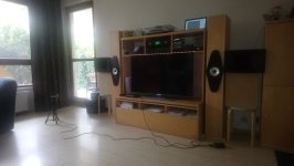
I'm in the process of "biamping" my entire surround system and so am in the market for some cheap, high quality class-D amps (those two design goals are not necessarily mutually exclusive!). I've been reading lots of datasheets, ordering a few to play with off aliexpress and then performing measurements as I go along.

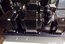
I've currently got a "Yuanjing" TAS5630 amp from SHENZHEN CAIZHIXING ELECTRONIC CO.,LTD and, after a single mod, I am very happy with it. And the best part is that it only costs $60!

Free Shipping TAS5630 300W+300W class d amplifier digit amplifier board We are the manufacturer on Aliexpress.com

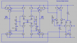
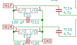
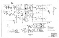
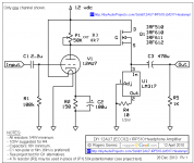
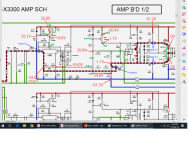
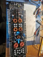
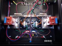
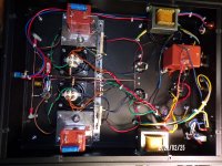
The design is straight from the datasheet -- even the PCB layout is similar. AFAICT, all the main resistor, cap and inductor values are as recommended. The TAS5630 seems to perform better than some other units I've tried based on chips like the TDA7498, TDA8920 etc. They've also added an OP1632 front-end, so you could use it fully differentially. This all means very good audio performance.

There are a few issues (most easily fixed):
* Noisy out the box.
* One component only rated to 40V, not 50V supply that TAS5630 is designed to handle.
* "click and pop" at turnon/turnoff (doesn't bother me).

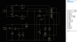
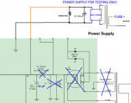
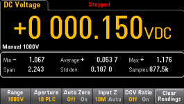
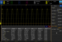
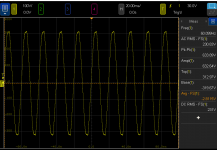
When I initially turned it on, the output was very noisy... so bad that I was about to bin it as a DOA dud. There was a lound buzzing that decreased when it was loaded. This is different from the hissing noise associated with cheap class-D designs, so I decided to look a little closer... A bit of sleuthing revealed that the supplied 12V power supply circuit (for OP1632 and TAS5630 GVDD) had a very noisy 10.8V output, resulting in sub-optimal performance.

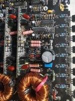
The fix is simple: replace the LM2575-12 regulator with a LM2575-15 device.

Explanation:
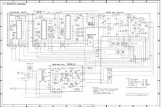
The LM2575 chip steps the main supply down to an intermediate voltage before a linear regulator (LM317) cleans it for use by the input differential amplifiers and TAS5630. Generally, this is a nice design for an efficient, low noise supply. But if the intermediate rail is at 12V (as the supplied LM2575-12 regulates), then the linear regulator is useless as it, too, is trying to regulate to 12V. So you get the minimum forward drop across the LM317 and about 10.8V into the highly sensitive amplifier modules. Crucially, this results in no linear regulation and a very noisy output, with the LM2575's switching breaking into the audio path.

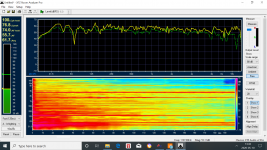
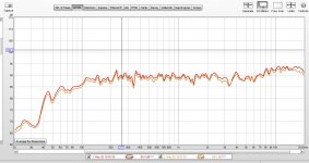
Replacing the LM2575-12 with a drop-in LM2575-15, 15V switching regulator, means that there's 3V headroom for the LM317 linear regulator -- sufficiently higher than its specified 2V forward drop. I have tested this fix on my unit and it has solved this problem. I can't detect any switching regulator noise in the output now. The frequency response is flat and THD+N below my measurable limits.

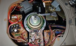
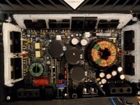
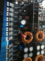
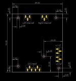
There are some unpopulated pads on the board for a 12V fan header (regulator is already populated), a couple of LED indicators, reset switch and a "shutdown" header. There're also solder jumper options for PBTL (jumpers pre-installed for two-channel BTL).

The only outstanding issue is that there're some clicks and pops on power-up&down. The TAS5630 itself is pop-free. The problem seems to originate with the OP1632 - TAS5630 interface. The OP1632 is supplied from afore-mentioned single rail 12V supply. It's biased to half the supply (6V). This, of course, changes as the rail ramps up/down. The TAS5630 doesn't shutdown 'till the rail gets to about 9V so there's some 3V change here before the output mutes. I don't care since the amps will be powered 24/7 in my application.

Further, I should point out that the National LM2575 is only specified to 40V input. It is being used outside its maximum ratings if a 50V supply is employed. I only use a 36V supply, so this is fine for me. But if you're trying to squeeze all 600W out of this module, you're gonna have a bad time.

For my application, I'm very happy with it and can recommend this module to anyone looking for a low-cost high-performance class-D unit.

PA 2x18" for Faital 18XL1800

I picked up a pair of these drivers for cheap and have decided to build a cabinet for them.

Link to the manufacturer's page: FaitalPRO | LF Loudspeakers | 18XL1800

Aims:
- Go at least as loud as four of my 15" subs
- Get nice and low - 30Hz would be nice
- Easy enough to move by myself
- Take everything a bridged Powersoft T602 will throw at it

After some playing with Hornresp, I settled on a boring ported box. 250L chamber volume, port of 1000cm^2 area and 80cm long.

That just about matches 4x 15"s (the 15"s put out a couple more dB at 100Hz, but I'm crossing over there anyway), while getting 10Hz lower. Today's super-woofers are impressive.

Now, the cabinet tuning comes out around 30Hz, which means there's a lot of excursion around 40Hz - 27mm peak (Xmax=20mm) if the T602 puts a full-power sine tone there.
So, I tested a driver in free-air conditions with one channel of the amplifier. Cone excursion got to in excess of 50mm p/p with a lot of wind noise, but there wasn't much sign of the driver "locking up" at that sort of cone travel. I actually ended up clipping the amplifier trying to make the driver struggle.

Probably fine, then. Under normal use there would be a few different frequencies happening at once, so I don't think it'll be a huge problem.

The port velocity gets to around 32m/s with a 3rd order 27Hz highpass filter in place. That's a little on the high side for linear operation, but it's another compromise - a bigger port would mean a bigger cabinet, and it's already around 1/4 of the total cabinet volume.

Driven to the ragged edge, this subwoofer will probably start showing compression in the 30-40Hz range, but there's still a lot of output potential there.


See attachments for a couple of drawings of what I've got so far. I don't think there's anything special happening with this design, but I have tried to avoid any bracing inside the port, in order to keep air flow as smooth as possible. The brace against the back panel is a compromise - I didn't want to leave a panel that large free to resonate.

I'm planning on a tip-and-roll setup for moving this around - the form factor should make life nice and easy.

The wood supplier has a 2-3 week wait at the moment, and I'm planning on placing the order some time next week. Stay tuned.

Chris

Attachments

  • Screenshot 1.png
    Screenshot 1.png
    58.4 KB · Views: 308
  • Screenshot 2.png
    Screenshot 2.png
    66.4 KB · Views: 294

Biamplification with modern receivers without a cross over?

I have a few old 15" woofers and a lot of odds and ends of compression tweeters in the junk pile. Combined with a few Hafler Transnova amps I have refurbished I thought I might make a few biamped speakers for general yard/pool party use.

If I understand the typical modern speaker that is designed to be biamped (not biwired) when you remove the bars that connect the woofer to the tweeter you are left with a low pass to the woofer and a high pass to the tweeter. I would probably just do an active cross over before the amps and do away with any circuits post amp.

But it occurred to me that lots of modern AV receivers can reassign the back surrounds to be used for biamping the fronts. And they have that automation where you plug in a microphone and they do room optimization. Would they be smart enough to approximate some sort of cross over function in the biamping? Do these tuning systems do any equalization? Or do they just control the relative volumes in expectation that the right cross over is already there?

Best,
John

Chuck got it right...

Chuck was right for sure.
We lost good hdmi air tv and was getting to the point I considered cable.
But had a hunch, turned and unplugged everything in house just like Chuck.
We then had great air tv again but with cell phones and lights off. Back to candles.

Over the next few weeks I'll gradually figure out how much emi is radiated by each device capable of broadband noise (using an IFR spectrum analyzer).
How much the hifi noise floor is raised is unknown.

The led lighting is top on the list as all of our 'bulbs' are now led.

Best regards Mr Chuck.

Help To My CIRUS iii - from 1994

i'm new in this foro - And I glad to meet you

I have a 1994 CYRUS III - which is about 26 years old , and until a few months ago it worked perfectly, but it started to give an intermittent failure which consists of:

When it is turned on and the initial check is done, it blocks, not completing it and some leds remain on (Tp-cd-tuerner, volume, etc.), other times, it starts well and after one or two hours, it blocks and turns off and the same leds remain on. The only way to start it up again is to disconnect it from the mains, it will be unblocked and after a few hours it will start working again or it will be blocked.

I have taken this equipment to the old CYRUS technical service in Madrid, which has been for 20 years although it is not now, it continues repairing and checking this type of equipment; they have checked it indicating me that it is faulty:


The front micro - socket whosepannel model is: AM/EP1V3/86 (according to what I have been told about this micro several versions or updates were made - CIRUS / Missión must know it.

They cannot get me that piece but it is possible that cirus has it or some equipment of second hand that this for pieces./scrapping etc.


I had sent to Cyrus UK a note telling this problem from their support page, and they has told me that have not codes and or facilites to repair this ampolifier model anymore

ANY IDEA from US.

I love this Apmpl.

Thank you in advance for your help,

Agustin

"Small" enclosure for Tannoy 15"

Hi guys,

I am about to start a new Tannoy project and need your advice.

The project will be using a set of old Tannoy K3808 (SRM). They will be reconed to K3838 with hard edge, have new HF diaphragms and new filters without controls. Basically only the frame and magnet will remain.

For enclosure I cannot (and will not) build 200 liters+ boxes so my limit is something in the area of 100-150l - and this leads to the question:

Do any of you have experience or information about the following designs for Tannoy 15" taking the relatively small volume into account?

1) Closed
2) Vented with port
3) Vented with acoustic vent
4) Rectangular GRF

Thanks a lot and greetings from Denmark

2 new blog posts

Here are 2 new blog posts
The first 1 i'm using multiple computers (5) and multiple speakers for testing....

Creating Mayhem | Timo's World all around the globe

The 2nd post is bout getting all speakers to work together by matching their phase responses and eq'ing the whole thing to in this case the X-curve

Creating Mayhem part 2 | Timo's World all around the globe

Enjoy

Help with a organ tube amps

Hello everyone
I hope all of you guys and ladies are doing well
My questions are these. I’m getting a old organ from someone near me. It’s a old unnamed organ, someone in the past had painted it. I will bringing it home tomorrow and will post photos of it then
I took the back cover off and could see countless small tubes and found the power amp, the power amp has two large transformers and a power transformer. More info on that tomorrow.
What I’d like to know is about the other tube banks. I seen they are labeled on the case
B,C, D and so on. I think they are for the different peddles and keys. For the tones
Tomorrow I’ll post photos of them as well.
What parts are good to save and pass on to you guys for your projects? I know it’s hard to say without the photos and so on.
I do know that I want to keep and use the tube amp for one of my systems. Once I get it out and see what all I can use and what I need to do for safely.
The lady did have it powered up and I could see all the tube glowing under all the years of dust. So hopefully that’s a good sign that it’s useable.
Until tomorrow
Thanks

JBL GTO 24001 high idle current

Got this amp for repair. Amp looks fine. All signals are in place, but it pulls more than 5 Amps. One side of the bank, slightly heating up, and the transformer for that side makes hissing noise. Changed some Capacitors on the audio drive board, because they were dead. Any suggestions?

Attachments

  • IMG_20200530_170958.jpg
    IMG_20200530_170958.jpg
    736.8 KB · Views: 208
  • IMG_20200530_171004.jpg
    IMG_20200530_171004.jpg
    973.3 KB · Views: 389
  • IMG_20200530_171015.jpg
    IMG_20200530_171015.jpg
    752.7 KB · Views: 192

My Altec Lansing 416-8a dilemma...

I have a pair of 420a transformed to 416a with a complete recone kit just completed. I dragged these things all the way from Canada in hopes to use them here in the Philippines along with a nice pair of Emilar 800hz/EA-175 horn driver combination.
I never thought about the high humidity and what the effects would be on the paper cones of the woofers over time. I would surely hate to ruin so, it saddens me but, I’m actually considering selling them. I’m still wondering if I need to keep the tweeters or sell them too.
What would you do?

Big tower speakers, very little low bass output, possible woofer attenuation?. Help!!

Greetings fellow diyers.
I´ve inherited a pair or tower speakers from my grandpa.

_MG_0079.jpg

As you can see, big speakers.. 10 inch woofers, 4 feet tall.

Now look at this.. I´ve been measuring frequecy sweeps with my phone from the listening position. Very little output in the sub bass range.

Screenshot_20200528-183627.png

This is the woofer crossover, I noticed a few caps in series which to my understaning are used to attenuate bass frequencies.

Woofer 1.jpg

Woofer.jpg

Tweeter and Midrange crossover

TwM.jpg

My setup: Room is 22x14x8. Big opening on the left side (I live in a loft). Long wall placement.

Setup.jpg

My grandpa had a passive subwoofer in his system also which makes my suspicious.

Looking at the woofer specs (Peerless 831727) and cabinet size I should be getting flat response to 35 hz with ease! Why am I getting so little bass? Can anyone tell me what´s going on here? Please help!! 😛

What makes a subwoofer loud?

Can anyone tell me how subwoofers work? Like I know all their parts and how they work etc… basically….but the only thing I can’t get my head around is this. I know there’s a lot of factors like T/S parameters, box, room etc… involved BUT so many people are telling me that to get loud is “mostly” the factors of sd and xmax correct? You have a specific sd of a speaker and to get louder you feed it more power causing the speaker to move more for more displacement OR you have a speaker running at say 1inch peak to peak and to get lounder you can increase the sd BUT here’s the thing if it’s all about “displacement” is which some people tell me then why is a $2000 SPL sub way way louder than a generic cheap $200 sub…them both having the same sd and xmax thus having the same displacement. I know people are saying well you feed the SPL sub 5000Wrms and the cheap sub 300wrms….but I’m thinking how does that extra energy from the SPL sub convert into audio being having the same displacement?

Dam confused here hahaha 😕
Cheers guys

Share your Ortofon Red experiences please

I ordered and received an Ortofon Red Verso today. Since it was the only Red version the shop I prefer had (and I needed instant gratification). I did however try to find out of that is the version I could fit to my RB250 arm. Since it looked do-able. I got the verso. Guess what? I won't fit the bolt is too short. No biggy since I can just unscrew the top plate and fit longer ones.

Here is my rant though. By using google I could not find a single sentence which arms the verso is suitable for. ( configuration for bottom headshells is the only explanation )

So now when someone googles at least they can find: "Do not order the Verso for your RB250 unless you want to diy". I ordered m2.5 length 6mm and 8mm now. Since the bolt that comes with it is 4mm.

Rant and info over. I'm curious about the experiences from other owners of the Ortofon Red.

Raspberry Pi OS - 64bit - announced

Hi.

Raspbian is now called Raspberry PI OS.

And a full 64bit Beta is available.

Finally. A 64 bit version.

Having a full 64bit version - kernel and userspace - are good news for us RPI4 owners.

I'm running my own 64bit Arch Linux since quite some time. It works really well.


These folks who run e.g. Moode can look forward to it, if of course Tim and the other OS folks decide to go for it. Maintaining a 64 and a 32 bit version could mean a lot more effort to them.


Enjoy.

Re: Se 2a3 golden era

Re: Se 2a3 golden era

in february 2020 I had the pleasure of mounting a SE 2A3 without compromise on a high-end black aluminum chassis

the transformer feeds the GZ32 valve, our CIFTE nibs, the smoothing choke and the head oil condos and the filtering JJ are common to both channels, then a 10H 100mA choke and a 2X100uF 500V F £ T condo per channel for conventional power supply. Y.

the 2A3 are heated alternately with a hum balance reostat which can also be measured in AC by the rca TPs at the back at the same time as the cathode voltage in DC

the 1: 1 IT is loaded by triode 6C45P-E.

the supply resistances are with wire wound the cathode resistors 2X2 1500ohm 10W and the 220ohm 5W wound audiogold ceramic non inductive non magnetic

the cathode capacitors of the 2A3 oil paper 30uF 160V and BC 100uF100V

high quality 3K5 42H 135mA output transformers

the sound is just superb beautiful

Attachments

  • 100_0176.JPG
    100_0176.JPG
    605.8 KB · Views: 201
  • 100_0177.JPG
    100_0177.JPG
    549.7 KB · Views: 201
  • 100_0178.JPG
    100_0178.JPG
    593.2 KB · Views: 195
  • 100_0183.JPG
    100_0183.JPG
    525.8 KB · Views: 193
  • 100_0192.JPG
    100_0192.JPG
    520.6 KB · Views: 196
  • 100_0168.JPG
    100_0168.JPG
    599.2 KB · Views: 109
  • 100_0171.JPG
    100_0171.JPG
    583.2 KB · Views: 130

  • Poll Poll
Need help! High output 3 or 3.5-way

What is the best configuration to meet the design target?

  • 3-way

    Votes: 7 46.7%
  • 3.5-way

    Votes: 5 33.3%
  • don't bother!

    Votes: 3 20.0%

DIY mates, I got the bug listening to some B&W 800s and want to build another set of speakers! I'm not asking to clone them but I do want to make something that can sound great even loud. While I may use a subwoofer for movies, I don't plan on it for music. Let's call it a mid-life crisis speaker build.

Here's what I'm liking so far
Tweeter: SB29RDC-C000-4
Midrange: NE149W-04
Woofers: 2x SB29NRX75-6, SDF-250F75PR01-06, or SB Acoustics WO24P-8
FWIW, I have speakers with dual RS225-8 now and they sound fantastic but don't get as loud as I'd like.

Let's be engineers about this and be critical when needed.

I am planning to use a miniSHARC processor into 8ch of amplification to run them active and choose my crossover points, but I may want to design a passive crossover at some point and the total impedance should be around 4ohm.

Great thread but want something that really shakes the room and sounds effortless doing so.
Open Source "Tower XL" thread

pass 2.0 preamp any good?

Hi all I haven't been soldering in many years now....but....

I need a preamp for my Pass F5 I built years ago, just as it is not quite loud enough. I have looked into the prospect of building a slightly more powerful version, but I'm not sure my heat sinks will be up to it, and the amp is so stable and reliable I don't want to mess with it.

I found this PCB for a "Pass 2.0" preamp on eBay. I wonder if this is the unbalanced version of the famous P 1.7 preamp??

SE class A MOSFET unbalanced + 128 step volume control preamplifier PCB ! | eBay

Any ideas? Thanks
Lucas

Baby Huey EL84 Builds & Speakers Post Pictures

Hi all,

I am hoping to build a Baby Huey EL84 this year and am in the process of sourcing components.

I am thinking of using a Russian equivalents of the 12AX7 and EL84 vales / tubes as they are plentiful at good prices.

As the output is 10w I am wondering what speakers people are using to work with this design. What sensitivity etc works best with this?

Would people be willing to post pictures of their completed builds and speakers they are using?

Thanks

Lee

Need advice for ReVox B250-S

Hi to all people,
Sorry if my question is on wrong place or copy, I search but I cannot find this thread.

I have an Revox B250-S amplifier, I'm very happy with that, but it's time to replace the electrolytic capacitors. This was done, now problem is gone, but by the way, I found a couple of discussions about replacing op amps, so please let me ask you if any of you have any advice will I try to replace the existing RC5532A op amps with something better?
Thanks in advance.
Regards
Leo

  • Locked
Deleting my account at diyAudio

I have just sent an email requesting the deletion of my account at diyAudio.

I do this with regrets. But in the last couple of weeks i became more and more convinced that a lot of trolling and/or usage of multiple accounts by the same person is going on at diyAudio. This makes it hard for me to keep interacting in a polite way, so i saw no other option.

Greetings,
Robert

Is this amplifier really stable and good?

Greetings!

I am building a guitar amp and I need a power amp of 100 W in 8 ohm. Would the folowing schematic be good, those videorrocola people claim it to be. Or would j be better of with a cheap tda7293/4 board from ebay? I dont need an amp that is high fidelity i need an amp capable of sustaining power without burnig out as i will mainly use it for metal. I would kindly ask for your Professional opinion on this.altough a really doubt that this amp is capable of 100w into 8 r, mainly beacuse of5200 transistors at output. 🙂
Link to schematic : construya un amplificador monofonico de 100 watts version 2.0

Thank you for keeping the forum consistent ...!

Just want to mention how grateful I am to see this site's feel and look had not changed over the years. That's almost 10 years!

Another popular local forum here had done yet another upgrade which is absolutely confusing to use and all external links broken. It is frustrating. We just want to build speakers not learning how to use a forum every year 😎

Cheers!

PP CFB toroidy OPT

Hi,

I'm building my second VT power amplifier (designing first). It consists of
- two OPS boards
- two DRIVER boards
- 6.3VDC PSU (DRIVER heaters)
- AC power control board
- 5V/12V PSU
- 120VA transformer for heaters
- 200VA transformer for HT and bias PSUs
- two toroidal CFB OPTs from toroidy.pl
- metal chassis
Maybe there will be also
- one analog meter for bias setting
- remote control board (on/off, volume)

Almost all components are ready. I'm about to design DRIVER board and I want to know your opinion. There are two DC coupled LTPs supported by CCS and powered by mosfet regulators. First stage E88CC, second stage E88CC or ECC99, heaters have configurable jumpers. Regards NFB, you can have global or/and local "Schade" feedback.

PP1-DRIVER-v1.3.JPG

Dual PCM1794A DAC Module - PecanPi

Hello,

I am in the process of designing a PecanPi DAC module that I already have a customer for. They are purchasing 100 of them.

I am putting this here to see if anybody else would like to join in to purchase these modules. Each module will be about $200 each. I will have final pricing in the next two weeks or so. The price will be lower with more buyers.

The modules will feature dual PCM1794A DACs in monaural mode and have specifications identical to my company's PecanPi DAC.

The module will have:
  • Balanced and single-ended outputs.
  • The input power supplies will be +/-12V (analog) and 3.3V (digital)
  • The size of the module will be 74 by 64mm as per the attached drawing.
  • The input signals will be I2S at 3.3V and support up to 24/192.
  • The modules will use my proprietary dual differential output stages with OPA1612 op-amps.
  • Complete reclocking with Crystek femtosecond jitter oscillator

Attachments

  • Module.JPG
    Module.JPG
    66.2 KB · Views: 461
Projects by fanatics, for fanatics
Get answers and advice for everyone wanting to learn the art of audio.
Join the Community
507,758
Members
7,887,164
Messages

Filter

Forum Statistics

Threads
406,169
Messages
7,887,164
Members
507,758
Latest member
Cindy