Playstation 1 as CD transport (SPDIF output)

I have some playstation-1's, some modded some stock. During the mods I managed to zapped the audio section of one board..... Maybe it can still work as a transport, I thought, all I have to do is pipe out the signal and use it to drive an external dac. It turned out the AKM chip's input signal uses Eiaj format, while I need I2s format to drive a TDA1541 dac.

Maybe there is a select pin in some chip upstream that can set Eiaj / I2s? Well, the research turned up nothing, I don't have a schematic and couldn't find datasheet for some of the chips.

And then there is this CXD2510Q chip in the upper left corner of the board. I downloaded the datasheet, and was looking at the pin out's. According to the datasheet, Pin#60 is "Dout", Pin#59 is the pin to enable it.
...
...
Dout? :beady:
hmmm, like the Dout pin in a CXD2500?
...
...
... somehow I remember somebody somewhere mentioned the Dout in the cxd2500 is SPDIF, maybe this 2510Q has spdif output as well?.....🙄
....
....

So here came my little experiment. I still have a stock SCPH-1001, which I don't mind adding a digital-output to it ("stock" means stock sound, no modification to the audio out). might as well use that. If the experiment goes wrong and kills board, I will only be out 10 ~15 bucks.

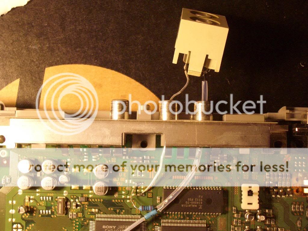
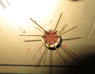
The first step is figure out how to get to pin60 and p59. I pulled the CXD2510Q off my "completely dead" 1001 board (long story short, the board got destroyed when I accidentally shorted the 7.6v line to the 3.6V during an all-linear external power supply upgrade), and looked at the trace under the chip. Pin 59/60 are not connected to anywhere. See photo. Signals will have to be tapped directly from the pins.
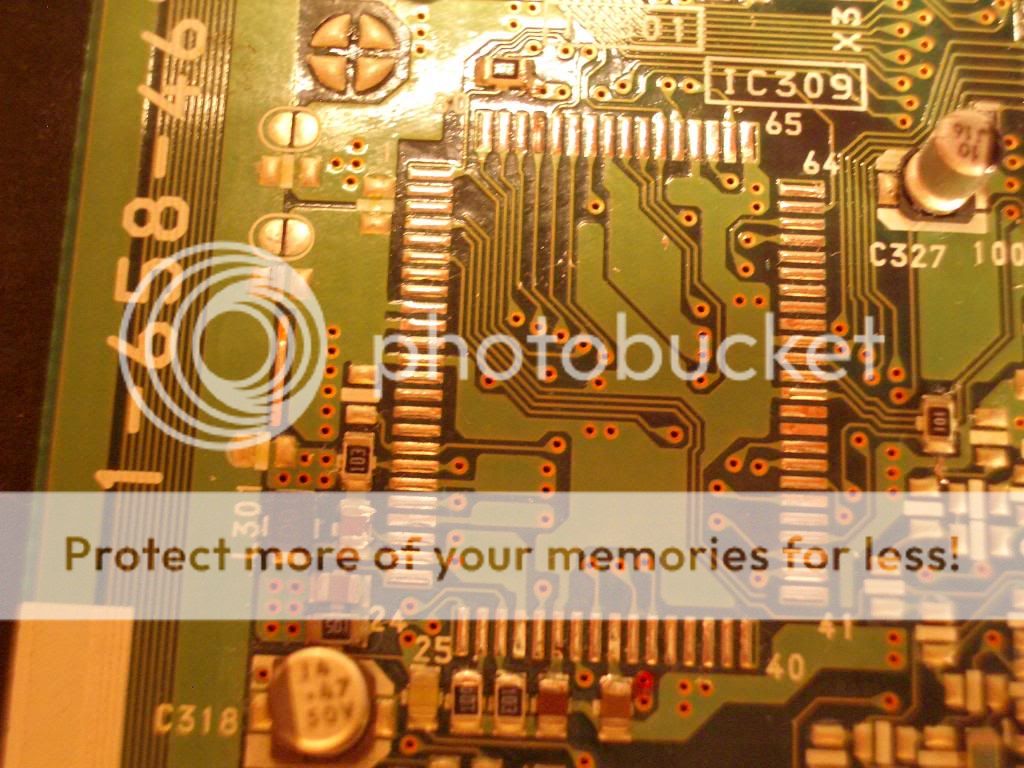
IMGP2813_zps8ea5e645.jpg


The next step is to lift the pins off the pad for easier access. I suppose you can solder wires directly to the pins but the chance of bridging is pretty high, so I chose to lift the pins. Pin 59/60 were carefully lifted up using a fine tip dental pick while the soldering iron tip was touch the pad. It can be done without magnification, though I did use a magnifier to check and make sure there is no solder bridge under the pin.

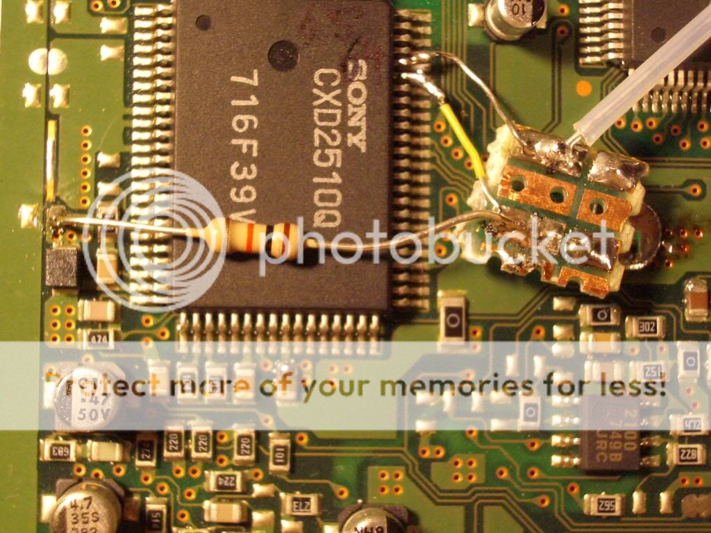
Now connect the wires to the pins. To prevent stressing the pins, I added a little pieced of perf board as anchor (there is a piece of wire coming up from the underside and soldered to two pads of the perf board, then the anchor wire is soldered to a large pad on the 1001 board), connected thin 28awg wires between the anchor board and the lifted pins.

piping the SPDIF signal out:
-- A 300 ohm resistor is soldered to the pad (on the anchor board) that links to pin60, the other end of this resistor goes to the center pin of digital-out RCA socket;
-- A 10k resistor is soldered to the pad that links to pin59, the other end of this resistor is soldered to the upper pad of L301 (left side of CXD2510Q), which is V+. This enables pin60's output.
-- A 100 ohm resistor is connected between the digital-out socket's center pin and the ground.
-- of course, the socket's barrel is connected to the ground.
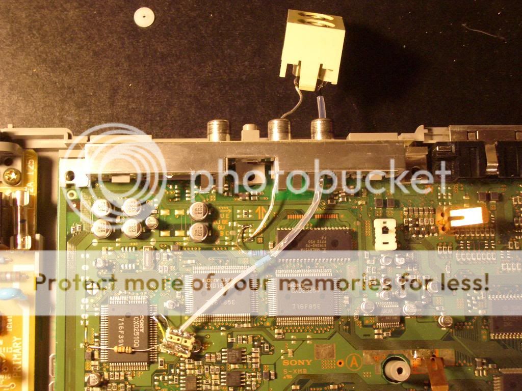
IMGP2815_zps2921e1c6.jpg


IMGP2816_zps6e887383.jpg


IMGP2812_zpsb237467e.jpg


Put everything back together, connect a digital cable to my little modded Zhaolu D2C DAC --> HCC86 hybrid amp --> Fostex T50rp headphones, and press "play" on the playstation remote........😱 😀 Music is playing.. And the sound is smooth, much smoother than the analog-out (yes, my modded D2C is smooth... 😀)
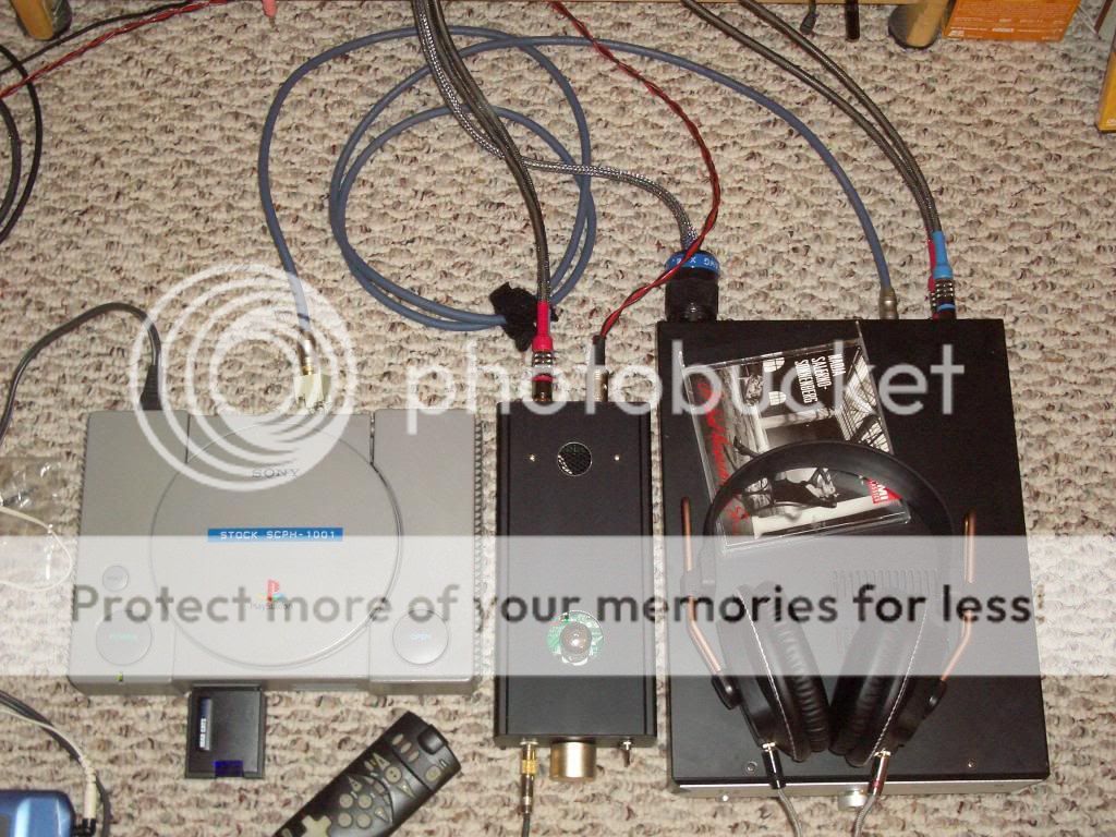
IMGP2807_zps28cb2a96.jpg


There we have it, folks, the PS1 digital-out mod. You only have to mess with two pins, add two pieces of thin wire, three resistors, one RCA socket and one ground wire. Simple as that😉 The playstations are cheap and plentiful, they are well built, reliable, laser adjustments are easily accessible. Not to mention a remote control can be added easily. What is not to like? Everybody should have at least one PS1 transport, don't you think? 😀

Now how about an Ubber PS1 CD transport? anybody? The spinning transport thingey can be easily mounted to a heavy block of something (wood, copper, granite, gold) and suspended via.... anything from rubber band to coil spring to magnetic levitation devices; use linear supply to provide power to the board (better yet, battery)..... come on, push the envelops, the sky is the limit 😀

Vented box alignment: gradual droop a good idea?

This is a newbie question. This is my first attempt to design a pair speakers. I've used SW to measure the T/S parameters, including Vas measurement using delta-compliance method. I'm now modelling the box using Unibox, and I have a question about what final low-end response to go for.

I want this box for music, not HT, and I don't want "flat till 20Hz". Even then, my drivers have an Fs of 42Hz, which is higher than what I'd like to work with. In a vented enclosure, if I tried getting a maximally flat alignment, I was getting the knee of the curve at a fairly high frequency. So I tried lowering the Vb, and I am getting a very shallow drooping curve, followed by a knee at a much lower frequency.

To my (totally inexperienced) eye, this gradual droop followed by the knee seems like a better alignment than a flat graph, because I expect that room reinforcement will neutralise the gradual droop very well. I'm also going to have a downward-firing port about two inches from the floor, so the low freqs will get amplified even more because of the floor, I believe. Here is the graph Unibox is giving me. See the high F3 but the low knee point:
An externally hosted image should be here but it was not working when we last tested it.


The impedance graph looks like this:
An externally hosted image should be here but it was not working when we last tested it.


Is this gradual droop a good idea? It's not possible that I'm the first person who's tried this, though I couldn't find any mention of this thing in Dickason 5/ed. (In fact, Dickason's entire approach to vented box design seems anachronistic after using unified box modelling software.)

Can I simply keep lowering the Vb arbitrarily like this in Unibox? Other than cone excursion, is there any limit to how low I can set Vb?

Any comments and feedback will be really useful.

Dac Magic 100 PSU

Hi guys. I'm looking for a little advice. I have a Cambridge Audio Dac Magic 100 which I'm happy enough with for now. But I only have the "Wall wart" power supply. I have spotted the Cambridge Audio linear power supply on eBay. My question is, would this be much of an upgrade? I know we're not at the high end here but for €100 would it make a difference?

Thanks 🙂

Chinese headphone amp kit

I've been looking at this kit. Mostly because I need something for my workshop but also because I have the valves and transformer already.
Assuming I have a correct schematic, I have a couple of questions:
1. Shouldn't there be a coupling capacitor before the grid of the output valve?
2 The blurb says its possible to use 6080 valves on the output stage but considering they are famous for having a 3A heater filament - that would be a short cut to little mushroom cloud from the lt317 regulator wouldn't it?.
I'm still learning here so any help would be greatly appreciated.
An externally hosted image should be here but it was not working when we last tested it.

self answered (maybe) question about solder-technique

Hi!

I don't recollect where I saw it, so unfortunately I can't link to it:
I once saw a picture of a finished board, where the resistors were wonderfully elevated something between 1 - 2 mm. Aside an advantage for temperature-issues, I guess this is mainly for aesthetics.

how is this done?

Soldered from the frontside with some support under every part? (I can't imagine any other way, but this seems to be quite a finicky burdensome job...)


Thanks for any tips!
best
david

Rockford Fosgate T1500-bd repair help

Hi,
Newbie to the sight with limited experience. My T1500-bd quit working. After opening up amp I notice one of the 75344G MOSFETS burned up (Q1003) along with the 47.5 Ohm resitor (R1009). Removed parts and want to order new but am not quite sure what resistor to buy to replace. My research indicated it was a 0805/2012 after measuring it but when I look at the options available I don't know what tolerance it is. Help?

Reading many of the T1500-bd threads has taught me alot about repairing this amp. I assume it would be wise to replace Q1004 & Q1001 since there are next to the bad Q1003 MOSFET?

Additionally, I had a hard time melting the solder for Q1003 to remove with my Weller Ungar 921ZX solder iron. I eventually cut it out and removed as much solder as possible before it would heat up enough. Never had this before repairing other elctronics. I assume its due to the copper thickness in the layers of the PCB. Any suggestion on install would be appreciated.

Once I have the new items installed I can report back and hopefully continue on to solve problem with help.

Thanks,

Greg

Attachments

  • IMG_6305.jpg
    IMG_6305.jpg
    159.2 KB · Views: 295
  • IMG_6306.jpg
    IMG_6306.jpg
    77.1 KB · Views: 239

Testing Speakers - Really Quietly

There was a bit of discussion here: https://www.diyaudio.com/forums/mul...e-driver-output-capability-6.html#post6277664

On what happens when speakers are used way below their maximum capability.

Now, the test I did looks fairly conclusive - I was reliably collecting data from speakers that I couldn't hear acoustically, but a sensitive microphone was able to pick up the sweeps just fine.

That test speaker was a Kef KTS3001SE, a 4.5" coaxial, driven by an Akai AM2250 amplifier - nothing state-of-the-art, but they sound pretty good.

I'd like to do some more testing at very low SPLs, to see if anything does show up with different drivers etc. So far, we have one datapoint which suggests that speakers are linear down into inaudibility. It might be an outlier, or it might be typical - I don't know.

What I do have, though, is a set of very different drivers, a selection of amplifiers, and a willingness to test things.

Here's the list of drivers. I don't want to test all of them, but am happy to test a few.
- Seas H1252 - 8" aluminium cones
- B&C DE250 - 1" compression driver
- Some no-name 4" poly coned drivers
- Bose 2.5" full-range driver
- Fostex FE126E w/P10 treatments
- Tang Band W6-1139 mini-sub
- No-name 8" PA coaxials
- Faital 10HX230

Amplifiers
- Cambridge CXA80 (my daily driver HiFi amp)
- Crown MA5002VZ
- Crown MA12000i
- Powersoft T-series

My instinct says the CXA80 is the obvious choice for this testing. The Powersoft amps have DSP baked-in, although I could use a digital feed from my laptop. With the kilowatts of power available, though, I'd be concerned they'd be operating "down in the noise". Thoughts on that?


The microphone will remain a Beyer MC930, and the USB interface will be a Behringer UMC202HD. Despite it's budget pricing, the UMC202HD has a very low input noise, close to the theoretical lower limit based on thermal effects etc.


If anyone would like to send drivers in for testing, we can talk about that in the future. For now, I think it'd be best to see if there are any differences between drivers, so we should take extreme examples, such as Seas H1252 vs 8" PA coaxial, and Fostex FE126E vs no-name 4".

I'm hoping to get around to doing some measurements in a few days time, and will report back when I do. In the mean time, any suggestions or encouragement would be welcome.

Cheers, all.

Chris

Soundsmith Sound Signature

Hello ,


I might be interested by a soundsmith cartridge but it is always difficult to buy a1000 $ cartridge without testing it .


As this is a Moving iron , may be I could get some idea about the sound .


MM even with difference have a signature sound like MC have them ( colder and tighter bass than MM ) as I believe .


What would be a Moving Iron signature ?


I remember having a long time ago a B&O mmc20 , if I recall the sound was between MM and MC with a less extended treble , analytic but not as cold as MC I have heard .


Thank you for your advise


Regards

WTB Tram preamp by DIY HI-FI Supply

WTB Tram or Other DHT Preamp

I have not had much response in connection with acquiring a Tram II. Frankly, I would consider others and am not necessarily locked in on a Tram II. Does anyone have any other DHT Preamp for sale? I think I would prefer a 101D, but would consider others. It does not have to be working or complete as my tech and I can likely square it up. Thanks in advance!

DCX2496 vs t.racks DSP 206 anyone tried both ?

I need to buy another processor for my system. I am on my 5th DCX. The last 4 have all gone wrong with the frying eggs thing or random channels cutting out......

The DCX I use now has been ok so far 😀 (I need another unit to run my centre channel and subs)
I had the t.racks DSP 206 recommended to me in another thread as a better option than the DCX. (better sounding without the need for upgrades) I'm a bit wary as I don't know much about it.

Has anyone here used both units ? TBH I don't have a problem with the 'stock' sound of the DCX so upgrades for it are not an issue. Personally I find the DCX extremely easy to use It's just the reliability issues that bother me. (maybe I'm a little bitter that my last 4 went wrong.)

If the t.racks does everything the DCX does and is more reliable then maybe I should give that a go ?

Thanks,
Rob.

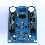
Nac152 power supply clone board lm317

I am new to this site so apologise up front for my lack of understanding. I have see a clone power supply board as a copy for. A naim nac152 preamplifier power supply advertised on AliExpress and ebayuk it is advertised as a nac152 lm317 dual +24v adjustable power supply kit. It shows a four terminal connection for -v 0 +v can anyone tell me what this should connect to ? I assumed it might be a potentiometer to adjust the voltage output but as I’m a newbie to all this I really don’t know? Any answers will be appreciated ! Thank you ! Lm317 adjustable power supply Module Board NAC152 two road+ 24V + 0-dual power supply kit T0562 I’ve tried to attach a photo as an attachment to help . Thank you all.

Attachments

  • 825675E7-D036-4D60-8C6F-B5E948A764B9.jpeg
    825675E7-D036-4D60-8C6F-B5E948A764B9.jpeg
    562.4 KB · Views: 94

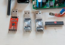
Where can I buy a USB Sabre DAC?

Hi

Lately, I decided to try DACs from different companies.. I also want to include in my tests a Sabre DAC..

In ESS's website, it seems that all their DAC chips expect to communicate in I2S, and unlike other companies that create DACs, they don't have some chips that include a USB controller built-in (so the chip would be a USB Controller + DAC).

Can anyone please recommend me of a DAC Product or Board that is Sabre based, and has USB connectivity? (and hopefully in a reasonable price also)

Alternatively, Is there some way to get a USB<->I2S board, which can then be connected to any DAC that expects I2S? (do all DACs that expect I2S communicate the same way over I2S, or it changes. If it changes, then it makes this second question irrelevant..)

Thank you very much

Anyone know the Sumo Theorem DAC?

Seems like when Sumo went belly-up they took all all their documentation with them. Anyone have a schematic for this unit or a service manual or something of the like? Mine has a non-functional coax input and I believe the automatic on/off isn't functioning properly either. The unit works via its optical input, so hopefully there's just a broken wire or bad solder joint or something along those lines, but if I could find a schematic to check component values against, well, that'd be awesome.

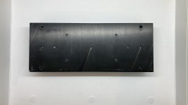
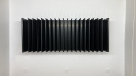
FS: Heatsink (damaged) from ACA

This is a heatsink from a Pass ACA. I broke off a screw in one of the PCB mounts and drilled it out. In the end, I decided to buy a new replacement heatsink. So I have this unused heatsink that has a hole drilled out. To use the hole, you would probably have to drill and tap it. Best offer, Chicago area. I am selling other items as well, so I can combine shipping.

Attachments

  • IMG_0009.jpg
    IMG_0009.jpg
    497.4 KB · Views: 193
  • IMG_0008.jpg
    IMG_0008.jpg
    607.7 KB · Views: 192

Easy and low cost: IRF540/9540 amp

Hi all,

I completed my first amp a few months ago. It was more a test than really something to listen to. It used the 9240/240 Mosfets.
Now I want to make a more serious amp, but still keep the cost low and the circuitry simple. I've found a very easy schematic with not much components. I'm going to make a few of them to sell to my friends.

diagram.gif


I'm going to add somethings myself; thermal compensation, DC protection, inrush current limiter,..

This is the website where I found it 100 W 8 ohms MOSFET amplifier with IRF9540 - IRF540 | Electronics Circuits Diagrams

I know some of you don't like V-Fets and schematics from that kind of website but what do you think of the circuit? Any major drawbacks?

Thanks

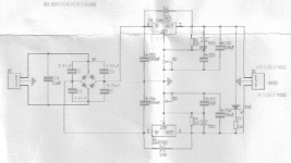
How to use DCin instead of ACin?

Hi,
Got a board from ebay delivering +V and -V with LM317/LM337.
The input power is supposed to accept both ACin (3-27V) and DCin (5-40V). ACin connection is obvious, but I cannot get any clear help from the seller regarding how to use DCin to power the board. Is it possible to simply connect DCin to the ACin slots? Or should the DCin be connected somewhere else?
Here below are some pics, hope you can get an idea from the scans.
Thanks in advance for any help.
LM317-LM337.jpgsch.pngboard.png

JBL 2226H + Beyma 8CX300Fe = High SPL Full Range?

Continuing with my quest for a high SPL studio monitor -

I am wondering what the problems will be with this combination:

JBL 2226H + Beyma 8Cx300Fe

-jzU0VtJ65xBf7uP0FVFxFVZsYxMJEGnQBbvuSzYYLTKLUhuos6Zazfq0Pspw6Fqf-ofUw1ax6ITr88tbtCs35YE1N3A8_IQahPBRO9fnL8Po6_WBACYJNorhG4zAkp3Rx9o-gG3-Q=w2400


My WinISD simulations show continuous SPL of 113 dB with -3dB point @ ~30Hz (mounted in 2p/half space conditions).

UUK-Y8_wGVTdaEKtwfDfsLyOALGNQ9WboAXMP40Acex4qNDOnEw7hM_5G5QpcOVnD666A0X_C0W9sVJcSEk9n5jyPwNHzz3s5UVQpVTz35u2C1ZklOvgoEWT-65RIZAjZXX1gGpepw=w2400


Excursion doesn't seem to be a problem...

Hs1FxR-7wKKsYqIHAPpttr7Ft959nwSHE31Nt2cCLZShL0pDIqYpIDPjUDDDeKtFfqnMw_zCX8HOnF9IQsZEJ1pltiLNNgD3EZrNHtGvdAqcErEMQaV8hOJXooZfzkdD7o7scBLDiQ=w2400


And if I am reading this correctly, max power required by the 2226H is <250W..., so I can get by with a Hypex Fa253 handling amplification, crossover and DSP duties...

5Lg8vgWiQyPIHi7oFeQOCVumv7-Lwww6MxRYOwTNs5Jnd1SrBuemd-2DB14vDJDJKy3BT4qLUIbcd0cElzs1zlFVH_g98__uxpPnxt4q6ofXQ-u2KsEXQubKR1amOc_gWVeI9pEHXA=w2400


What are the potential problems with this arrangement?

Most Bass from 1-2 Cubic Feet

I was contemplating building a portable speaker system for music and it raised a few questions. If these have been addressed in other threads please let me know.

1- To produce sound we need to move air. For bass, we need to move a lot of air. So larger diameter drivers and higher Xmax will naturally move more air. How is it then that certain cabinet designs can produce higher SPL? For instance I was looking at Bill Fitzmaurice site and how a Titan 48 with a single 15 will produce more SPL than a reflex cabinet with 2x18's. Assuming the twin 18's have similar Xmax, there is a huge cone area advantage and thus more ability to move air...so how does the Titan produce so much SPL? I guess I just have too elementary an idea of how sound is produced.

2- Along the same lines as question #1 and most applicable to the portable project, what design would produce the most bass from a 1-2 cubic foot enclosure? Looking to get down to maybe 35-40hz or so if possible. What general combination would likely work best? Smaller driver in some kind of horn or TL? Larger driver in a simple sealed or ported? I am assuming any given design would require a high Xmax driver.

Thanks

Is there another way in Ltspice to see the slew rate of a schematic ?

Hello

Is there another way in Ltspice to see the slew rate of a schematic ?

I use the settings like you can see in my image, it show more a square wave than a real slew rate measuring, since the frequency response affect the slew rate square image and result.

Thank

Bye

Gaetan

Attachments

  • Capture-slew rate Ltspice.jpg
    Capture-slew rate Ltspice.jpg
    168.6 KB · Views: 184

Replacing 25A rated bridge rectifier with 35A ones.

Hi guys, do you think it will cause any problem?? The rest of the parameters (reverse current, fusing current voltage etc..) are exactly the same. I personally feel it should be ok since its just the rated current capacity. I cant find the 25A one so getting the 35A one instead

There is a fuse at rectifier and it am keeping it the same so i feel it should be enough.

Design Q -> 4 Mono-Blocks, 2 speakers, Bridged or Parallel?

I checked the forums for this topic, but most of the hits were in the chip-amp forum and nearly all were dedicated to the "how to" of wiring existing, pre-built amps in each configuration.

That's all well and good, but it doesn't help me understand how to set up the design parameters to get the desired output power from the partially designed mono-blocks I'm modifying/building.

I tried the Solid State forum, but got no nibbles. There are a lot of from-scratch designers here, so I thought I'd try asking it here instead.

The situation :
I will have two mono-blocks per channel in an amp I'm working on (in simulation and a single rough prototype). They will be driving an 8 ohm speaker/crossover. I'm looking to get about 50W/ch, and rough math says I should have about half that power in each mono-block, but I'm getting confused with the math, and could use some help.

Two mono-blocks means each supplies half the power, or 25w. The math says to get 25w into an 8 ohm speaker, each mono-block will have to put in about 1.75A driven by 14Vrms. However, the topologies of the two possible solutions require different math...

What I think the solution space looks like :
If I understand Bridged Mode correctly, while we get twice the voltage swing, each amp sees half the resistance. That means we're trying to drive 25w into 4 ohms, and the math gives us results of 2.5A at 10Vrms. Each mono-block provides that much voltage, at the same current, so that's 20Vrms (total) swing at 2.5A, for 50w of power to the speaker.

If I understand Parallel Mode correctly, it is the opposite. Each mono-block sees twice the resistance, but contributes to the total current, so you get twice the current you'd expect for the resistance. In this case, 25w into 16 ohms results in 1.25A at 20Vrms. But each mono-block provides that much current at the same voltage, so it's 20Vrms at 2.5A (total), for 50w of power to the speaker.

The BIG question: Did I get the two circuit topologies right?

If so, bridged looks to be the way to go, from ease of setting up the power supply and modifying the circuit. Getting a clean 56Vpp (20Vrms) signal sounds like a bit of a pain...

Next up will be to get to the output voltage of 10Vrms... from line level input. That will take a total of 30dB in gain (31x gain from 0.32Vrms, consumer line-in levels, to the final output voltage of 10v).

Presently, the amp design gives about 12dB of gain (per mono-block), and I hope to get a fair bit more out of it, but I doubt I'll get all the way to 30dB gain out of such a simple amp design.

So, if I understand this part of the problem correctly, I'm looking at a pre-amp that can punch it up part way. The preamp will have to add (30dB-PowerAmpdB) worth of gain to get from consumer line-out level to 10v, and achieve 50w/ch, correct?

Thanks in advance,
Ken
(yeah, I'm a EE, but I'm digital to the bone - this analog stuff is crazy complicated)

Community M200 drivers, TOA horns, Peerless, etc.

One pair of NIB Community M200 midrange compression drivers. These are 2" throat drivers that go from 400-4kHz, very flat except for a very narrow notch around 3.2kHz. Low distortion. $375.

https://www.communitypro.com/sites/default/files/M200.PDF

I also have one matching SH494 horn. $75, but shipping on it will be expensive due to the size.

https://www.communitypro.com/sites/default/files/SH494_spec.pdf

One TOA HCD-904 horn/compression driver combo. 90 x 40. 630Hz minimum crossover. 16" x 6.5" x 10" (D). $50

Two TOA PCD-690 horns. One with piezo driver, one without. $10/pair.

One ProSystems 4660 1.375" compression driver. $25.

Pair Peerless 811655 1" soft dome, horn loaded tweeters. Around 95dB sensitivity. $45

Photos at link below.

Dropbox - Speaker - Simplify your life

Prices do not include shipping. Will ship international, but I will charge extra for this depending on the amount of unreasonable time it takes to do paperwork. Shipping drive units with charged magnets in them, can require a lot of time, especially if they will be sent by aircraft.

All drive units are located in the Northern California Bay Area.

LH0002 pin identification help

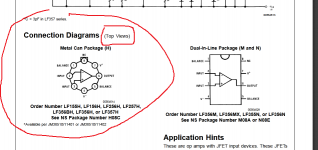
I have some National LH0002CN , the military version, like the HA can which i am using as buffers in a phono preamp and i think i might have connected it the wrong way although not sure about that.The datasheet doesn't specify if the pin asignement is for the top view or the bottom view, so i thought that maybe the National LF356 in the same can that i have a few might tell the right pins.I used the LF356 pin map in the datasheet to connect them in circuit and now the can get hot within 30 seconds...1 minute after power up without doing anything.Truth is that i am supplying them at +-20v which is close to its max +-22v max supply, its measured voltage output in the circuit is identical with its measured input and in my room it's warm, maybe 30 degrees celsius...I can't connect the thing to a turntable and headphones amplifier right now to check if it buzz out anything, but i wondered if anyone would agree that the LH0002 datasheet pin map is the same with the LF356 and it's the bottom view as in the real thing photo.

Attachments

  • lf356.png
    lf356.png
    58.2 KB · Views: 155
  • lh0002.png
    lh0002.png
    66.1 KB · Views: 175
  • IMG_5014.jpg
    IMG_5014.jpg
    1 MB · Views: 149
  • lh0002b.png
    lh0002b.png
    420.3 KB · Views: 145

Achieve good time domain behaviour to produce single cycle sine

Hi,

I want to reproduce single cycle waves (below 200Hz) using a 12" driver (either woofer or subwoofer). As I understand the time domain behaviour of drivers don't allow single cycle sines. With a real life driver, the oscillations take time to build and time to die which is fine for music but not for my application.

Following are some of the ways to circumvent the problem
1) Use a servo controlled driver, servo control has good time domain behaviour.
2) Use multiple smaller drivers, say 8 of 5" drivers, smaller drivers will inherently have better time domain behaviour.
3) Use a driver with very high BL, the high BL will generate lot of back EMF, the high back EMF will allow the amplifier to control the driver better yielding better time domain behaviour. Of, course, very high BLs damp the lows, but thats not a problem since EQ before the amp can bring up the lows, as shown by Don Keele in his paper http://www.xlrtechs.com/dbkeele.com/PDF/Keele (2003-10 AES Preprint) - Nom vs True Eff High BL.pdf

What are your thoughts?

Thanks and Regards,
WA

Building a Neurochrome mono amp for speaker measurement, what exactly do I need?

Hello there,

I am looking to build a Neurochrome mono amp just for measuring speakers.

Currently I am using an Adcom GFP-565 preamp and Adcom GFA-5002 power amp connected to a Focusrite Scarlett Solo, but I am looking for something more "portable/compact". Ideally it would be half an Adcom GFA-5002/535 with a volume knob and a single input.

There are several possible amp options from Neurochrome, mainly the LM3886 DONE RIGHT and the MODULUS-86 that would fit the bill.

I am not sure which of the two to build, one is easier and cheaper, but I only want to do this once.

What else do I need?

Obviously a power supply, I could either build the Neurochrome POWER-86, or possibly buy the Connex Electronic SMPS300RE. Is there a big difference between the two? What other high quality off the shelf power supplies are commonly used for either amp? Unfortunately Neurochrome has discontinued the SMPS-86 power supply or I would simply buy that.

I see many builds with a toroidal transformer, so I assume I will need one as well?

What type of potentiometer is used for "volume" control, and where would it fit into the signal chain?

Is an INTELLIGENT SOFT START circuit or GUARDIAN-86 MONO SPEAKER PROTECTOR required/highly desirable?

Anything I have missed?

Obviously these are all noob questions and no, I have not built an amplifier before, but I do know which end of a soldering iron to hold and have build electronics in the past.

Thank you,

David.

Panasonic obsolete Bjts replacements

This is in a Nad 218THX amp.

Any recommendations for replacing 2sd1975/ 2SB1317?

(Need to replace all)

Been looking and looks like 1943 / 5200 from ON/fairchaild could be ok. Although freq is at 30mhz instead of 20mhz. ONs are hfe 80, also a version with hfe 50. Not sure what to choose. What difference does it make here. Can’t find exactly what hfe the Panasonics have.

Can i keep everything else the same? Right now res are 0.22R. Bias is recommended to be at 8-10mv
Same with new ones?

Would be nice with just a swap.
Pinout should be same too and to-264 also.

Thx for help

Crimson FET 2.5 Issue 1 Module Schematics

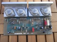
I picked up 3off Crimson FET 2.5 modules on eBay very cheaply and i would like to get them tested/working. Does anyone have a schematic they can share or know the operating specifications for this module? They seem to be a bit of a rarity and not nearly as well-known as the Crimson Elektrik bipolar transistor amp modules. I know Brian Powell has been very helpful in the past and he may have posted these already?. This is not a complicated board so would be fairly easy to trace out the design but it would be helpful to get any information about them from anyone who knows or has a working amplifier already 🙂

Attachments

  • RIMG1261.JPG
    RIMG1261.JPG
    353.1 KB · Views: 281

Hgh inductance, high impedamce speaker cable

I'm running bi amped Exposure Super 18 power amps into a pair of Acoutic Energy AE1 mk2 speakers. I'm about to move my racks and will need longer lengths of cable (10m).

I understand my power amps are happier used with a high inductance, high impedamce cable, (I think that they don't have a Zobel network on the output, but don't quote me on this).

I'm currwntly running 24 yr old Linn LK20 for bass and Gale ? silvered for top, but these cables will be to short for my new location in any case.

I'm happy to spend sensible money on cables but not looking at crazy uber wires costing over £5 per metre, esp given lengths required.

Any cable recommendations?
Do I need to worry so much about what I use for the tops?
What in speaker cable terms are considered to be high capacitance and impedance values so I can check Blue Jeans, RS etc?

Any suggestions or advice for suitable cables would be appreciated. Bear in mind I'm no techie.

tubelab sse mono blocks????????

I have a pair of small power and output transformers

Power transformers are 480 center tapped at about 60ma 6.3 volts at 2.5 amps
output transformers are 3k to 8 ohms about 5 watts.


High voltage will be limited to about 300 to 320 volts with ss rectifier.
I was thinking about using a 6av5 in triode and 6ab4 as a driver. 6av5 will be biased like a 2A3. Does this seem like a workable idea?

Hello from Austria

Hi everyone,
I am a music lover in the first place and have been into the audio hobby for about 40 years (more and more enjoying the DIY route in the last 10+ years). I have been following this great forum for quite some time and have enjoyed it / your contributions a lot. Many thanks!

I hope to be able to contribute one or the other thing of interest in the future.

Best wishes,

Norbert

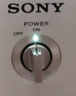
Where to buy a power switch & knob

I used to own a small Sony power amp model Ta86 and really liked the power switch. If I recall correctly, it was a 1/4 turn, rotary type with a solid and satisfying click sound when turned.
Do you know where I can find something like this?
I’ll have questions about it’s implementation when and if I’m able to find one.
Thanks for looking

Attachments

  • 81C87A8E-5976-453C-804D-3E1A9BF76EC7.jpeg
    81C87A8E-5976-453C-804D-3E1A9BF76EC7.jpeg
    243.1 KB · Views: 131

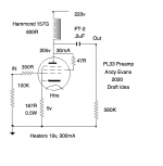
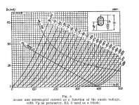
EL33 line stage or driver tube

Having read good things about it, I bought some PL33 which is the EL33 equivalent with 19v heaters at 300mA. EL33 is derived from the EL3N which has generated some good reports from users.

So I was wondering about triode operating points, and came up with the attached. I'd welcome some feedback from anyone familiar with EL33 or similar line stages. It's probably not too far away from a 6V6 for example. I'd be using it to drive a 300b.

Attachments

  • EL33 Pre .png
    EL33 Pre .png
    43.4 KB · Views: 608
  • EL3N-triode curves.jpg
    EL3N-triode curves.jpg
    88.8 KB · Views: 533

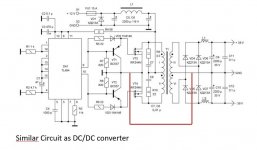
Car SMPS for Soundbox GND question

Have bought a car SMPS for amplifiers on eBay.
180W DC12V To Dual 32V Boost Power Supply Board For HiFi Amplifier Car Amp | eBay
Intention is to use it in a soundbox with a car lead acid battery.
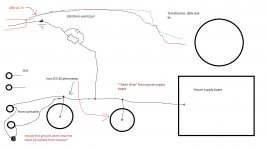
As I would like to use the 12V from the battery to feed a DSP and BT board, I'm thinking of connecting the input GND of the SMPS with the output GND.
See picture with the red connection. I think the schematic is very similar to the one used for the eBay SMPS.

This way all Gnd is attached to the battery minus pole, creating a common reference point.

I can't think why it should not work .... can anyone else??

Additionally I'll use a small charger based on CN3768 and a laptop SMPS for charging the battery: 12V 3A 1-1000AH Lead-Acid Battery Dedicated Charger Module Board for UPS Car | eBay

Attachments

  • eBay SMPS.jpg
    eBay SMPS.jpg
    79.5 KB · Views: 97
  • SMPS circuit.JPG
    SMPS circuit.JPG
    63 KB · Views: 113

How to measure time delay, pleas help

Hi there
I am setting up a 3 way stereo, I am 3-amping and is using a DSP to as an aktive x-over.
18" up to 100hz
12" from 100 up to 1400 hz
1" CD from 1400hz and up

The DSP offers me the opportunity to make a time delay for each of the three drivers, so I have so I have sat and listened to 1400hz test tones and steb by step bin aging delay to the 12" driver hoping to hear the test tone getting higher and higher as the sound from the 12" driver is getting more and more in phase with the sound from the 1" horn loaded compression driver.... If then suddenly the level of the test tone is getting lower and lower as I ad delay to the 12" I will start taking back som of the delay added to the 12" driver.
Test tone will be at it highest when time alignment between the drivers is right.

This approach have bin working to some degree, but I juts wonder:
There must be some measuring program that can give me a more precise value for time delay.

I have an UMIK-1 usb microphone.... any suggestions ??🙂

Seas DXT vs Seas 27TBFC/G + WG300

Hi everyone 😀


I've been very interested in waveguide lately. But cant really seem to find my ground.
Since I have a small midrange and an existing 4 way design. I want to build something like it, but with a little different design and more constant directivity. So I found the Seas DXT that is so popular in Kii3 and Grimm Audio, which I also like to listen to, when I visited different exhibitions.
The DXT might be a little to small.... maybe. But I do have a 5" hard cone midrange for the project.
Then I saw on sound imports, that they have guide for waveguides - haha 😛
SoundImports | "Wave guiding" your favorite tweeter. - SoundImports
What if I use the Seas Prestige 27TBFC/G with the Monacor WG300..... would that make a wannabe Seas DXT, but larger?
I can see on Heissmann acoustics, that the DXT can peform well. But since the price is very close - then I could not help to think that this combo might work really well.
Anyone seen someone do this?


Regards

Bose 901 Series V review

Hey, folks. I review speakers and drive-units and thought I'd share a recent review/test I completed of the Bose 901 Series V. It would take me an inordinate amount of time to copy/paste it all here so to save my sanity I am sharing the link to the review on my site:
Bose 901 Series V Speaker Review

I'm proud of this one. Lots of work and time went in to creating this. About 20 hours so far. But I learned a lot and hopefully others will, too.

Simulating Troels’ DTQWT using.... ?

This is an interesting speaker, with two different speaker drivers coupled onto one ‘horn’. I’d like to know if this can be simulated fully using Hornresp. And, in general, whether Hornresp allows the simulation of multiple drivers with different T/S in the same horn as well as with sound radiating from the front side of the cone. It’s not a simple TH simulation because there are drivers with different T/S and it’s not a Synergy simulation because there is output from the front of the radiator and neither is it a BLH be because there are two different drivers.

If not, I assume Akabak can do it? I’m unfamiliar with both tools and haven’t found the answer after searching the ‘net.

I’ve no immediate plans to build this speaker from Troels, it is more an example to help me ask about the capabilities of the simulation tools.

Attachments

  • 753F880E-4B5E-4A67-B75B-D84A2FB5C3E7.png
    753F880E-4B5E-4A67-B75B-D84A2FB5C3E7.png
    114.7 KB · Views: 370

(help!) replacement driver for Spendor classic 3/5

Hello All, My first post here.

Writing in from India. recently purchased a 1993 release of Spendor classic 3/5, in transit, one of the mid woofer's frame just Obliterated (not sure about newer ones, but older ones had plastic frames).

i am now left with a pair of 3/5 minus 1 mid woofer. i have been looking for replacement speakers for sometime now (no, spendor cant help in anyway, they suggested i move on)..

anyways, considering spendor made their own woofers back then, this has a diameter of 143 MM, which limits OEM parts for most part except 1 - Morel CAW 538 5" Cast Frame Woofer, this looks like it'll fit right in the rebate provided in the speaker cabinet.

the tweeter on this is a Vifa, so was tempted to consider
1. Vifa PL14WJ-09-08 Woofer Mid Range
2. Scanspeak 15W/8434G00 Discovery

unfortunately, both the vifa and scanspeak are 149mm, and the rebate in speaker cabinet is 143mm...so some woodwork/cosmetic damage would need to be done...

so, the suggestion is need is..
a. which speaker should i go with...assuming i cant do much about crossover settings..neither do i understand how this works
b. if the vifa/scanspeak...any suggestions on how ot do a neat job on rebate...

anxiously looking forward to your valuable suggestions..

Thank you!

Matisse Fantasy clone : Lite LS 27

Hi DIY audio friends!
Is there someone who tried with Matisse Fantasy preamp, the one from LITE LS27 pcb? There are some MF clones but this one is identical to the original. Does anyone has details about connections or test positions and measurments?
I have a basic schematic and I have almost finisfed assembly ! I am expecting some more items and the bulbs...
Thanks !

Mains transformer vibrations and circuits

Hi ! i have a line preamp solid state with a mains transformer soldered and tightly screwed to the preamp circuits pcb. The transformer is of the type in the picture below
An externally hosted image should be here but it was not working when we last tested it.

I wonder if its vibrations could in some way cause any noise issues.
I am thinking about mechanically decoupling it in some way from the pcb but it is not that easy because it is designed to be soldered directly to the pcb.
I am thinking about soldering some wires to its terminal and mount it upside down with some rubber sheet/isolators under it
I have seen pictures of preamps where the active circuitry pcb is mounted on a frame on rubber feet ?
Have you ever thought of anything similar ?
Thanks a lot,
gino

Attachments

  • IMG_20200705_165123.jpg
    IMG_20200705_165123.jpg
    371.9 KB · Views: 165

Apogee Stage Panel Speakers FS England

Selling my Apogee Stage Magneto-static Panel speakers. In excellent working order. They have been modified by me to work with the internal passive crossover or with external active or passive crossover. Cosmetic condition is fair. As with all panel speaker they need at least 1M from rear wall but can go close to side walls. They were my main system speakers for several years and the only speakers I tried that could better them were Quad Electrostatic ESL-989 which I have now. Derby UK collect only. Limited demo possible within Covid restrictions. £650.

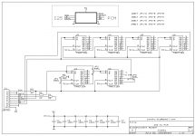
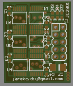
I2S to PCM for old R-2R DACs

Hi,
Becasue of pendemic time and more spare time I finished old forgotten PCB project.
This is nothing new (just a shift register),is often used in DIY DAC design.
The assumption of the project was to miniaturize the PCB.
I used chips in TSSOP14 case and RC elements in 0603 case.
The dimensions of the PCB are 23mm x 28mm.
The layout can be configured (jumpers at the botom side) for 16,18,20 and 24 bit DACs.

Regards,
JarekC

Attachments

  • JC2801.png
    JC2801.png
    6.7 KB · Views: 180
  • JC2801PCB.png
    JC2801PCB.png
    240.5 KB · Views: 176

Tang Band W8-1772 Impressions.

I have run T/S tests on a pair of 1772's using a Smith & Larson Speaker Tester. The drivers were broken in for one hour a Xmax. Average of three runs each for the two drivers are:

Re ohms 7.28996
Fs Hz 42.59512
Zmax ohms 28.85236
Qes 0.44508
Qms 1.31602
Qts 0.33256
Le mH 0.04414
Diam mm 165.5
Sd mm^2 21512.25
Vas L 72.76948
BL N/A 7.4432
Mms g 12.6453
Cms uM/N 1106.912
Kms N/M 905.7046
Rms R 2.57074
Efficiency % 1.1911
Sensitivity dB(1 watt) 92.76138
Sensitivity dB(2.83 volt) 93.166

The S&L tester does a constant current test, so the numbers will differ somewhat from testers that do constant voltage. The results are not surprising. the Vas lower than published is what I normally see, although I would have expected Qts to be somewhat higher than published rather than lower.

index.php


Nothing untoward here. I won't try to explain the glitch at 150Hz for now. I am impressed that there is no reflection off of the surround at ~1000Hz. That big old aluminum phase plug plus (I presume) a shorting ring very effectively kills any impedance rise.

One thing of note: The 1772's suspension is either not progressive or only weakly so. Unlike most Fostex drivers that can't be over-driven to Xsus, it is very easy to bounce the TB off of the back plate. Some care will be required is high SLP low frequency applications.

I will mount these drivers in my FT-2000 cabinet (MLTL). I won't be testing on an EIC baffle, so my FR plots may well have some box defraction artifacts in them, but so be it. It may be a few days before I report back.

Bob

"Earthing" in tube preamps

Building myself a tube phonoamp, and I have some questions about earthing/grounding. In phonoamps we have the grounding screw close by where the phono chassie socket are, were the plugs from the TT are connected.
I wonder if this earth/gound point must be isolated from the chassie?
Se my bad drawing...And thanks for a great forum!

Attachments

  • Jordings skjema for DIY rør Riaa.jpg
    Jordings skjema for DIY rør Riaa.jpg
    88.2 KB · Views: 346

GW1858 vs random Wharfdale 18" in WAW OB

I pulled the trigger to the tune of $200 for a pair of Goldwoods, as I thought I could do a little bit better than the Wharfdale 18" drivers I spent $100 on. The Wharfys have a measured fs @40 Hz, otherwise I cannot find any specs on them - other than that they're 4 Ohm speakers.

Checking the Goldwoods, they do fs at ~ 30, just as the spec says. They are 8 Ohms. A reknowned driver for WAW OB use. Replacing the Wharfs and tuning things up, I'm not hearing any difference at all in the bass performance of the system.

They could be returned, but that just seems too "American/Walmart/Amazon" a thing to do, to me. The seller did and the speakers are doing everything they're supposed to do - it's just that $200 worth of difference isnt showing up in my own perceptions. The Wharfdales are actually the better constructed speaker of the two Chinese manufactured units, having a cast frame - vs stamped.

I suppose I'm not the first DIYer to drop some cash on a piece - and hear nothing at all from the additional expense.

The OBs have no H frame for the woofers. Should I make a push to get at least the back tunnels constructed to bring these to a bit better life? I'm using a reverse rising response to 35 Hz starting at about 110, where the top has already started to rolloff. The attached pic shows what the OB looks like.

Thanks!

Attachments

  • Left_Speaker.JPG
    Left_Speaker.JPG
    792.6 KB · Views: 94

Repairing SVS plate amp - loose RCA connector

My sub started to hum, I noticed that the female RCA terminal was loose and if i position it a certain way it would sound correct. repair should be a walk in a park, just remove the plate amp, solder or glue the RCA connector poof, job done.... until you noticed that the back side of the RCA connector is covered with a black plastic box

An externally hosted image should be here but it was not working when we last tested it.


An externally hosted image should be here but it was not working when we last tested it.


Why is there a need to enclose the backside of the RCA ?

Any ideas what to do next, should I remove the box ?

Nad c372 red at first startup, and green at 2nd atempt an than works fine

Hi guys

I own a Nad c372 that i have used for several years, and always worked fine.
Recently it has started with a red ligth and no sound at first startup at the day. Then i turn it off again with the remote, and turn it on again and then it works like it should. (green light)

But im thinking that this problem is something that could be a indication off a bigger, and maybe expensive problem.

Any toughts?

Thank

Regards

FS: Elekit TU-8500 w/options

SOLD - Selling my delightful Elekit TU-8500 tube preamp which includes a solid-state phono-stage. Excellent, inexpensive introduction to separates or someone needing its small footprint. Includes all options (upgraded caps, resistors & phono-stage opamps) I've been using it since building in Dec/Jan and it has been terrific. However, I was offered a high-end preamp I've been lusting after for years at a "too good to be true (almost)" price last month and it is just enough better that am selling the Elekit. I purchased new from Victor Kung at VKMusic, the importer/distributor for Elekit and other high-end boutique Japanese audio exotica. Google VKMusic.CA for further links to tons of excellent info and reviews on the DIY forum and elsewhere.
In addition to the Mundorf MCap Supreme SilverGold coupling caps, includes the Takaman resistors & 2227P opamps.
Am also including your choice of a pair of JAN Phillips or Sovtek LPS tubes (both r much better than stock) with the Chinese originals. And, the installed pair of 4562 opamps that I purchased later and find just barely better than the 2227P option. Either have worked great with my MC cartridges.
I was in the process of gathering parts for the installation of the Muse electronic remote control https://www.diyaudio.com/forums/swap...es-volume.html when the other preamp 'deal' fell into my lap. I will also include the boards & programmed controller/processor chip if the new owner wishes to complete same.
Have been zero issues with the preamp since I started listening to it in early Jan. So good that I haven't bothered tube rolling and only rolled the opamps as a point of interest. There are additional opamps out there to roll should one be interested, including some high-end ones like MUSE01 & Sparkos Labs, who also offers some high-end voltage regulators. Endless fun, should you wish.
Purchaser pays $650 plus actual shipping cost (will ship international) and any Paypal fees.
Thanks.
SOLD

Attachments

  • Elekit5.jpg
    Elekit5.jpg
    153 KB · Views: 439
  • Elekit6.jpg
    Elekit6.jpg
    62.4 KB · Views: 439
  • Elekit7.jpg
    Elekit7.jpg
    73.7 KB · Views: 431

SSE grounding and general spot check

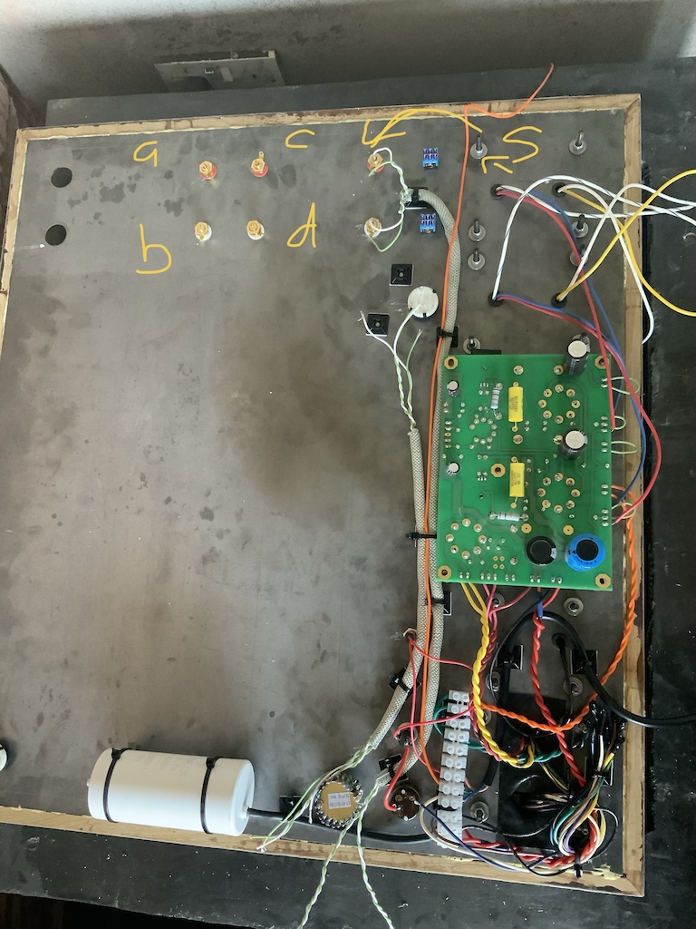
Hi all, sorry for another thread about grounding, I have a layout that’s not like any other I’ve seen here so wanted to double check a few things.

So my plan is to use the output transformer bolt as a star ground (S), then ground the board via the RCA. Do both channels need to be ground¿ there is only one on the official diagrams.

Also, I have three sets of input jacks, all mounted to the chassis and insulated from the chassis by the plastic washers.

The other two (A,B,C and D) are for me to fashion an
‘Input selector’ by plugging in and out rca patch cables, like an old synthesiser.

Do I have to ground them in the same manner, to the star ground¿…
Also the switches for power, UL / feedback and volume all contact the chassis, should I ground them separately or will the fact that they contact the chassis suffice¿

I have used Neutrik SpeakOn connectors to hook up the speakers, there are no exposed metal parts on these, i assume they don’t need to be ground¿

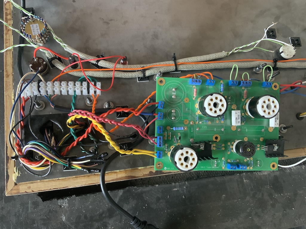
Finally, does anyone see a potential issue with the signal wires being so close to the power at the bottom of the image¿ I’ve shielded them just in case
p5pb19066232.jpg
p5pb19066171.jpg


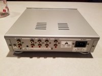
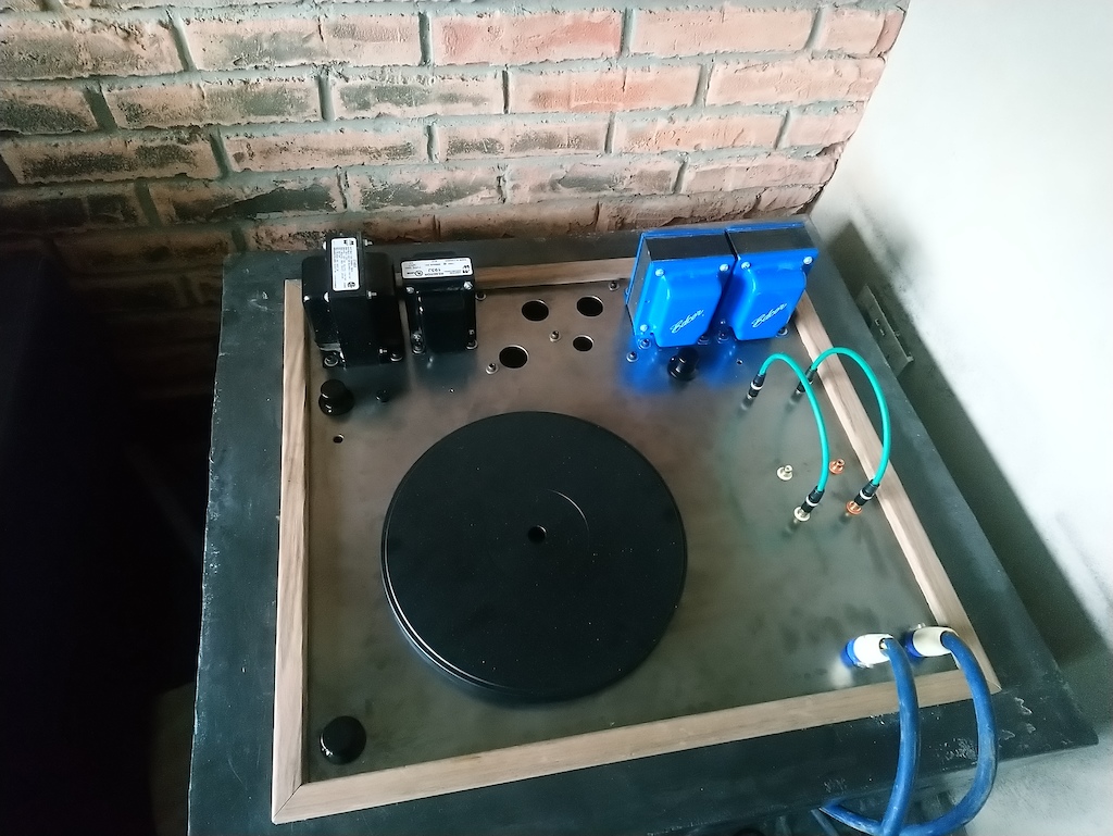
Here is the top side, I’ll be housing my turntable here as well. The two green cables will allow selection between phono pre amp and a wired connection from my computer. The two holes for switches above are UL and feedback. I’ll hook these up after I power the amp up and test it.

p5pb19066199.jpg

6AV6 TO 12AX7 conversion?

Hi all,, Hopefully not too off topic, but would modding out the 6AV6 to accept a 12AX7, leave me w/the same gain factors of 100?, and might there be any appreciative sound difference? It's a Bogen CHA-10 single ended amp currently w/a 6AV6 mic preamp tube, a 6AU6 for an unused phono section, 1-6L6 & an EZ81 rectifier, headed to the bench to be RnR guitar worthy. So, 6AV6 to 12AX7, same gain>overdrive, same sound?
A waste of energy? Thanks!! Be well all!

Behringer Co. dead?

Hi, I got a Behringer BXL 3000 Ultrabass Combo and would need a circuit diagram! I have no trouble to get diagrams from Peavey, Carvin .... but no way to contact Behriger! Ex-German company, now seems to be swallowed (?) by a Chines one.... and the only contact possibility I can find is via "musictribe", but this platform does not allow me to register (complaining about wrong "country" and wrong "phone number", whatwever I enter there :-( )
Does anyone have an idea how to get in touch with them?
Still selling their products so there has to be a way....
Regards
Michael

Sub-mini to 9 pin base

I would like to make adaptors for using sub-miniature tubes in regular 9 pin sockets, so that I could compare the performance of sub-minis with their 9 pin tube brethren.

The 8 pin bases are readily available, for example:
10pc bakelite octal 8pin tube base for 6sn7 el34 power plug | eBay

I’m looking for a base that would plug into a standard 9pin socket, to solder the flying leads of the sub-mini tube to. Problem is I can seem to find any “naked 9 pin bases” for sale. Could someone help?

Kicker sx 1250.1 burnt power transistor help

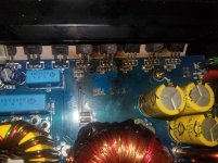
I have a Kicker SX 1250.1 Date stamp on the board says 2004 3 13

The low voltage rca input on the amp was being finicky, would have to apply pressure on the cables to get it to work properly at times. i decided to take the cover off of the amp to see if i could fix the issue and found some burned MOSFETs in the corner. As far as i know the amp still works, unless it burned as i was taking it apart or right before. They look very damaged. I dont know much about amp repair. Im thinking of replacing all 5 of the IRF3205 transistors in that area.

I dont know much about how amplifiers work.

I dont know which IRF3205 to use, or what else to check/replace.
What kind of thermal tape to use? maybe silicone-rubber?

Any help would be appreciated.

Equipment i have: soldering iron, solder, vacuum de-soldering tool. Car battery. Multimeter. handheld oscilloscope.

Attachments

  • 20200705_164710.jpg
    20200705_164710.jpg
    578.9 KB · Views: 311
Projects by fanatics, for fanatics
Get answers and advice for everyone wanting to learn the art of audio.
Join the Community
507,784
Members
7,888,382
Messages

Filter

Forum Statistics

Threads
406,236
Messages
7,888,382
Members
507,784
Latest member
ys.zhu