Here I put my skin on the market.
Project is in the development stage.
The objective of this project is to build a
SPL dense compact solution for low crest factor music, I.E.: heavy bass.
All that reggae, bassy chill, full on PSY, techno, tekkno and other heavy stuff, in which long bass line happen to play for long loong minutes.
How do I do that?
Well, speakers are not built for this mostly at all, so some compromises must be taken into account. No free lunch, kids!
Basically, anything seriously compact in PA can only be ported or bandpass. Not much way around it, if same (good) bandwidth is to be achieved.
The issue of ported designs is, that they have significant cone excursion minimum in "most used" part of the bass band, and that reduces speaker coil cooling. On top of that, exactly at that frequency, most power goes into the speaker coil. So if full power goes to the speaker at that point on freqency scale, it is basically a toast within short minutes, sometimes sooner.
How come it wasn´t problem till now?
It was. Either the speaker burned, or heavily compressed, or strong limiting kicked in, kicking the output down by 6 or even 10db in some cases of even high end commercial products.
For "normal" content, it is not such big problem and this limiting kicked in rather gently and for short period of time. For heavy music, it would hinder the long term performance quite a bit.
What we gain: safety, low power compression and SPL compression, full bass, SPL density for box size, just 3dB limiter safety setting instead of 9-10dB. Low frequency mode giving fair SPL down to 25Hz.
What we lose: Maximum possible/peak SPL reached by about 3dB lower than conventional design. Also little of the Price/performance ratio.
How we do that properly?
In order to lower the thermal load on the speaker in compact design, it needs to operate in such a mode and way, that the impedance minimum and cone excursion minimum is avoided. In exact words, put the port tuning frequency outside the crossover pass band (lower). That will solve the issue. But of course, it will create another one. Otherwise this would not be novel approach at all. In this scenario, the speaker cone is forced to do most of the work most of the time. That means, it has to move a lot.
Most PA speakers "to date" are not built for that, so most speakers except the well chosen high end simply cannot do that. Those speakers will run out of linear excursion capabilities.
Objective in detail:
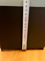
Box volume: Max ~210l / 7.4cu.ft brutto, ~92l / 3,25cu.ft net depending on the speaker.
Weight: ~34kg / 75lbs. Easy single person operation.
Frequency range: 40-80Hz flat, 35-110Hz -6dB.
SPL: 121dB/W/m+ according to Hornresp in halfspace.
This design could be made smaller, but A) for serious compromise B) If planned upgradability is dropped. More on that later.
Low power compression, low port compression.
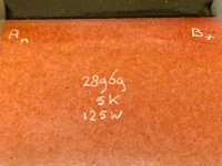
In this case, tuning frequency will be 29Hz.
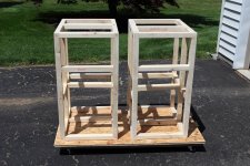
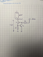
Basic sketch:
It is not my first rodeo with such design, and with RCF LF21N551 and barely with B&C 21DS115 it worked. Yet I sadly sold these, so it´s time to move little forward.
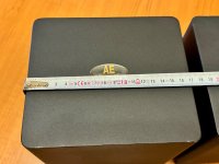
The wood used for outer walls is 15mm/0,59in baltich birch, speaker mount wall 18mm/0,71in the port, braces and back wall possibly 15mm/0,6in poplar birch.
The port is flow and "horn" optimized to squeeze little bit more performance out of the design than regular. Certain corners will be ground and smoothed some more. Thinking even about printing the port front-side into something more resembling of L-port.
🙂
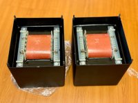
Driver needs:
As mentioned, high displacement volume. We are talking here 20-21mm of one way stroke to fully exploit the design. Either IPAL class drivers or something like that in future. Actually, I am kind of counting on that the technology will catch up with the design. We are almost there. Also 5,3" to 6" coil for more "oomph" in 35-40Hz region would help. But we are doing it now, so we use what we have...
In order to fairly utilize the box, we need over 1,8l of displacement (one way) and optimum would be 2.5l. Meaning, 3dB more to reach all box limits as port flow, distortion figures for speaker stroke in such volume, doppler distortion limit almost.... That´s where this enclosure options end. And that is 21mm of excursion for 18".
The new RCF LN19S450 would qualify, but not in the current box dimensions. This is just a prototype, some changes to allow for 19" driver could be made.
I have already ordered that, but the story is unfortunate - Released in March 2024, odrered in December 2024 delivery NOT confirmed by may 2025. I just can´t. You know what I would have to say about RCF...
Drivers that qualify:
Generally these with displacement volume of 1,8l and more, and Bl
²Re over 200:
That is, for example 18Sound 18NTLW5000 4Ohm version
LaVoce SAN184.50
All the IPALish drivers.
Drivers that do not qualify for feasibility reasons, but would work:
All similar drivers like B&C 18DS100/18DS115.
18SW115/4, RCF LF18X451.
Given the displacement limits, it would be just too expensive and not SPL dense anymore, or efficiency would be lower (more heating).
Why I gave the LaVoce pass: Remains to be tested, but Lavoce bass drivers allow for very large linear stroke. The SAN184.50 is marked as 15,5mm Xmax. If it is anything like 21" series, then it WILL work admirably till 16mm on regular basis. That gives it 1,95l of displacement volume. B&C on the other hand, has Xvar of 14mm, which is a bit of a stretch in my book, because suspension compliance dropping below 50% is at about 12,5mm That gives us 1,51l of displacement volume at 30% price hike. And so as much as I love the LOVELY 18DS115 it is rather out of the list. Not feasible. Would work, but at 1,5-2dB loss or more audible distortion. I am certain it WOULD stretch to these displacements, but possibly at too high distortion figure. Sad story so to speak.
Well, what if you pulled it all out of your a$$?
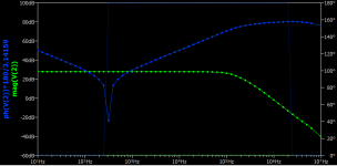
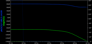
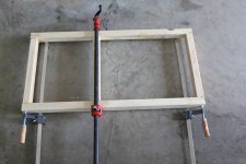
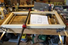
That´s where the reality comes in. Sims incoming, Prototype build will be done possibly by the end of this week, measurements next.
I also plan to make YT video about me rambling on audio topics and SAN184.50 review.
Suggestions, questions, opposition, all is welcome!