I'm building a $4000 speaker kit ... Which one?

I'm going to build one of these three kits ... Which one would you suggest. I can NOT lose. So I will go with the most suggested.

Satori SBA951
Scan Revelator B1371
Scan Illuminator B741

Here are the links ...
Satori SBA 951 Speaker Kit by Peter Noerbaek - Pair


B1371 Scan-Speak Kit by Peter Noerbaek - Pair


B741 Scan-Speak Kit by Peter Noerbaek - Pair


SBA951-Assembled-Front-200.jpg

1B1371_pair.jpg

b741-1.jpg

  • Locked
John Curl's Blowtorch preamplifier part II

Part 1 is here:
http://www.diyaudio.com/forums/showthread.php?s=&threadid=71189


Hi John,
I posted the following in a post I moved to the test equipment thread. It really belongs here, so I am going to quote it.

I don't know if you read that post, you didn't respond to it. So here goes ...
At this point, is there any reason to hide your actual schematics? It's an old design that depends on discontinued devices and careful hand construction. The PCB details are enough to stop a clone.

The reason I ask is that you could refer to specific design examples as you pointed out your design choices, or what you consider to be important concepts. It would be somewhat easier to keep things on track and clear to other people.

Considering the difficulties a normal person would have to begin production on anything, there really is not a lot to worry about there either. I do not want to make one of these, but learning from this would be very useful to many.

Just a thought John.

Let's focus on John's discrete design again. If we can reference to the actual design while we talk, it may help considerably.

-Chris

Edit: The original thread is here, a big thank you to stinius who reminded me that I forgot to link to the original thread.

Active micro 2 way bookshelf speakers with Wondom Jab5 amp

Howdy folks. I built a set of TG's Faital 3wc 15" at the start of the year. This gave me a taste for DIY. I'm half way through building a set of micro active 2 way speakers for my son to use with his electric drum kit, and for general use (and maybe to take when we travel).

Figured i'd post it up here in case anyone has helpful comments, or wants to build something similar and my build helps.

Am using:
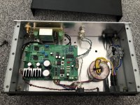
Wondom Jab5 (4 x 100w with DSP) - will use 1 channel per driver
l-1.png

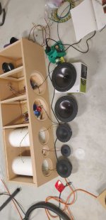
SBA SB19ST 4 ohm tweeters
SB19ST-C000-4.png

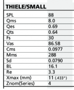
Dayton ND105 4 ohm 4" woofers
s-l500.jpg


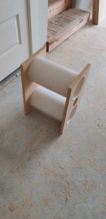
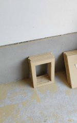
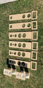
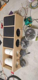
16mm MDF cabinets at 4.5L internal
Planning to muck around a bit with the DSP to see how low i can get them to go with a flat response.

My thinking is the amp's good for 100wpc, the drivers are 30w, so call it 60w peak. The amp's meant to be ok to 6 ohms, i'm asking it to deal with 4 ohms, but hopefully the fact that it's quite overpowered for the drivers means nothing melts.

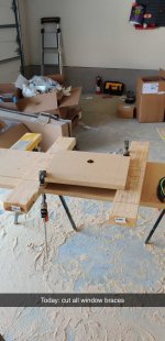
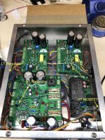
Have cut everything, and done a basic test of the amp last night to ensure it works:
Wondom Jab5 test - YouTube

Next up bench test using the PC control module and all 4 drivers.
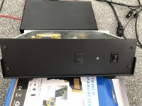
After that i need to mount the hardware in the cabinet. The 1 job i need to work out is how to have the plugs mounted, the 16mm MDF is too thick. I could rout it, but then it might be too thin. Do i use some hard plastic, or can i use metal - but i'm concerned about having a power plug mounted directly to metal... I'm not electrically skilled.

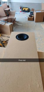
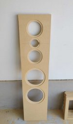
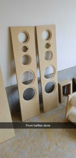
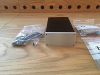
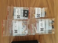
Few pics of the build so far:
250CB835-885B-4352-8D7F-24D0A3CCD4EB.thumb.jpeg.eb24ca2a144b251a6a70a3ef259c84d1.jpeg

3554585D-89A0-4D50-A9FF-96EDBB74C6DB.thumb.jpeg.9470bb55a8ab999a05cd691de7c3bab2.jpeg

8545291C-C2A2-4592-AE58-BD3FEBDFB8C7.thumb.jpeg.5a9c73d63484924e8451e95a5ee0d204.jpeg

F1450BDF-E4D7-4B45-9B47-FD4785AEFED7.thumb.jpeg.148d6560afd675fd904524de4d280064.jpeg

3127584F-82A8-4A0C-8371-5C5CA08B62A3.thumb.jpeg.d18cd2d40017fb7d7bc1cb2c77e469e1.jpeg
F2FEFF93-CAB2-4854-9FE2-0A7BB2D488E5.thumb.jpeg.c51f0a89426c4bb1aa1758b78b723326.jpeg
88C9A72A-15C8-443B-A902-B18721B33058.thumb.jpeg.727fbf02c8ca616bcb01d7f808e1ebe6.jpeg

A9DF3D0F-B5F6-4488-AB18-711C10FA19EE.thumb.jpeg.ed0b5e3c8b1c690383f9ac0b81ab3ec6.jpeg
27B49A42-65BB-466F-8E49-262C201A8C2B.thumb.jpeg.84df2dc9230439d4c12d3a17dacf6eb7.jpeg

Using Eclipse TDs for surround sound.... Need advice for centre speaker

I've been happily running a pair of TD508iis with matching subwoofer in a 2.1 configuration, and recently purchased a Pioneer AV receiver to experiment with a centre channel. Currently, I am using a smaller TD307ii as a centre speaker. It's a little smaller (100hz vs 80hz roll off) but timbre is well matched and performance is very similar for vocal reproduction. However, since it's a single 6.5cm driver, I find it's not really suited to the task... Clarity and volume is fine (sofa is only 3 metres away), but it's missing fullness / prescence. The cheap philips centre speaker I have is better in this regard (minus fidelity) as it has two drivers. I am wondering if it's feasble to wire up an additional 8 ohm TD307ii to the centre channel also to mimmick the dual mids config usually found in centre speakers. My receiver can run 6-16ohm speakers so running them in serial should work? Either that, or I'm thinking a similar egg shaped centre speaker might work.... E.g Kef's HTC 3001 Any suggestions would be most welcome

Gemini GVX-12P with random popping noise

Hello Guys.
I have a Gemini GVX-12P powered floor monitor that makes random popping noises when turned on. The noise does not disappear when it warms up. Any idea what to look for?
I noticed that the pcb with the input connectors has already dried out moisture traces on its solder side, maybe the amp pcb has them too, but I'll have to disassemble it first to be sure.
But I don't know if this has anything to do with the popping...
It seems to be impossible to download the user manual for these monitors, since my internet is too damn slow at the moment. I cannot find any schematics for these monitors.

Thanks in advance...

  • Locked
Why diyAudio uses inferior DHL

Why does diyAudio use DHL ex USA when FedEx operates ex USA too?

I ordered a complete ACA kit, the chassis has already arrived via FedEx yet DHL is holding up the parts ex USA, it was packaged and received by DHL USA Aug 4th yet tracking says it is yet to even depart the US.

Whenever in the past DHL has been involved with international freight there's always a delay. Why use this inferior vendor when FedEx operates ex USA too?

I'm sure others won't mind paying a little extra if FedEx demands, at least we get value for money. I hate parting with money when the service is a bloody joke! 😡

Resistor+Thermal fuse replacement

I'm repairing an amplifier - there is a Resistor with a thermal fuse in the power supply, and the thermal fuse has blown. This same component has been replaced at least twice before. It seems to last a couple of years and then go. We use the amp for a couple of hours each week on Sunday, and we aren't overloading the amp.


I'm considering replacing it with a non-fused resistor of the same value. Is this dumb? 🙂


The resistor+fuse is in the main power supply line. It is already in series with a thermistor, so there is double-protection. I also have the option of adding in a normal replaceable fuse. The particular resistor+fuse is also a custom part for Yamaha, so it's also hard to get, costs about $20 and takes me a couple of hours to bring it home and fix it. It would be a couple of minutes and very cheap to replace a normal fuse.


Any thoughts or suggestions?

Intermittent hum Rotel RA712

Hi Everyone,

This is my first post so please be considerate !
I am an amateur & just picked up an old Rotel RA712 very cheap which was very dirty but has cleanned up nicely. It had obviously been sitting in a damp enviroment since a long time.

No problem with the dim bulb tester, so I started her up and found the dc offset to be OK, so hooked her up to some speakers. The sound is really nice ...... but then there is an annoying intermittent issue with the sound on the left channel. On start up or suddenly while listening to music there is an audible hum suddenly coming from the left speaker. It is definately on the power board as input source or volume makes no difference

The dc offset at each speaker terminal (not pot to adjust it) is 30mv & 34mv, so not great but OK. The bias can be adjusted easily to within spec and is stable on each channel, except when the hum starts in which case the bias on the left channel increases significantly.

The strange thing is if i give a rapid burst of volume, the hum goes away or if if I touch the bias adjusting pot VR601 very lightly with a metal screw driver or the speaker fuse the hum will suddenly dissapears, only to come back a few minutes later, which would suggest an earthing problem.

I am at a bit of a loss what to do with my limited means. I checked all solder joints, cleanned all pots, fuse holders and compared all resistors/diodes on the left & right channels with no discernible difference found so far.

I only have a DMM & a capacitance meter, with no other tools.
Can anyone suggest what I should be looking for ?

Many thanks

Holton Precision Audio NXV-300R2++

Selling almost new Holton modules, only been tested for about 10 min.
- 2x HPA-NXV 300R2
- 2x LSP One
- NXVPSU One
- HPA-NXVolt One R2
- Holton Ac Mains Power controller

New price for all of this from HoltonPrecisionAudio is around 1200 AUD, not sure what i can get for these so im accepting offers.

- I also have a PSU with 10x Cornell Dubilier 10000uf caps, (unused)

What the hxxk is this Speaker Out connection of Vintage Solid State Amp?

Hello,

I recently got very old (60's) vintage integrated amplifier and it has weird connectors throughout. All of Inputs are 5 Pin Din which I understand.

The Power Cable Input has 3 Pin Din which I may be able to find a suitable connector to make one power cable.

However, the speaker out connector is weird and I have never seen one like these. Does anyone enlighten me what this connector is called and how I can connect to speakers?

Thank you...

wmmnlQG.jpg

TI Op-Amp Naming conventions

Could anyone tell me what the TI op-amp /NOPD designator means? I'm looking at the LF347BN and LF347BN/NOPD and struggling to find what /NOPD means.

Also: any links to the op-amp naming conventions used by TI? I haven't been able to find a comprehensive document. I have found out that the TI Tuscon and TI Dallas centers use completely different naming conventions.

Odd problem with eBay specials

Hi - newb here!

I have a weird problem with a pair of eBay special monoblocks I bought a couple of years back. They are silver shoebox cases using IRS2092 and IRFB4227 boards of a type I suspect folk are familiar with.

These amps have relays for activation / output, and these relays happily click and beautiful sound comes out of my esoteric Vienna Acoustics Beethoven speakers - provided I leave the case off each amp 😕

They have been like this since I got them, I had a case open to return them to the seller but the logistics of returning them to an address in the far east I can't write on a box accurately and pressures of work got in the way.

OFC for some time I just ran the amps in my rack in the study with the lid off, but enter Jackson, my wonderful two year old boy - he just loves to post CDs and anything else he can find into the open cases, in addition to terrifying me by putting his fingers in there when I'm not paying full attention (swear the child is going to be a Ninja).

tl;dr amps of an otherwise popular reference design won't activate the output relay with the lids on, is there a way to fix / diagnose this?

Rockford Fosgate T10001BD Repair Help Needed

I have a RF T10001BD. It came to me disassembled, MEHSA strips out, most of the FETs were shorted. I replaced the drivers, tested gate resistors, and set it in the frame (ground screws in place) without any FETs in it. Applied ground and remote, I have good gate drive coming out of the UC3526ADW Pin 13 (and all the way to the FET vias). Pin 16, however, has no output. If I lift R26, I get a sort of sharkfin wave.

I looked at the datasheet for the 3526 and I don't see what could cause this, it looks to me like they are both driven from Toggle F/F, but that stuff gets a bit above my head.

Any recomendations?

Boost circuit input current runaway

Hi,

I've a circuit using a MT3640 which is I suspect a clone of the TLV61048, at least it's pin compatible. TLV61048 is preferred but long lead times and not in stock anywhere means I had no choice.

XI'''AN Aerosemi Tech | XI'''AN Aerosemi Tech MT3608 | DC-DC Converters - LCSC.COM

I'm boosting 5V to +/-14V. I've noticed that lower than about 6.5V efficiency drops massively. I've tried:

Inductors from 1.5 to 5.6uH (Coilcraft XEL4030 so well within current saturation)

8x 10uF X7R (4x on the PCB but doubled for a test)

Without any success. Looks like's it's the MT3640 and the 2A current limit is *******. Anything else look amiss?

For reference most the current draw is 12x NE5534's.

Attachments

  • 20.png
    20.png
    19.5 KB · Views: 146
  • 10.png
    10.png
    147.6 KB · Views: 125
  • Untitled.png
    Untitled.png
    25.4 KB · Views: 113

Targa Hexfet 2CH700

Here I go with a stumper! Seems this amp has two banks of PS's and only a single TL494 and an output array which is mildly impressive. At first look from like 5' away I thought it was an Arc Audio / Clarion design. Half the output transistors are GREEN which means it must be good amp and needs to work once again. But then I saw an oddball black output transistor so someone might have thrown a monkey wrench into this thing at one point.

Seems this amp is stuck in protect. But I have no way to verify as there are absolutely ZERO indicators. I have not pulled the board out of the synd. Its drawing 0.00A but the PS does blip up to 0.50A sometimes.

TL494
1. 0.010
2. 3.450
3. 0.091
4. 4.95 <-- Protect?
5. 1.473
6. 3.680
7. 0
8. 13.4
9. 0
10. 0
11. 13.4
12. 13.4
13. 4.061
14. 4.96
15. 4.031
16. 0

Found D507 cracked but a new 1N4148 didn't help. See it middle of board.

2-way cross-over design

Hi Guys,

I'm using a JBL 2234H woofer (8 Ohm) in a 5 cubic ft cab tuned to 28 Hz using 6" port. I'd like to have an 800 Hz cross to a 16 ohm TAD 4002 compression driver. I will only use the very best components (that I can afford) when I build them. If anyone has an appropriate JBL version that would be fine also.

Thank you in advance for your help,
Henry Zuranski

Separate references to circuit ground?

AndrewT offered me some advice on the layout (as I also did it on strip board and was unsure what was important) I had all of the -ve side connections just along a strip from load back to the diode bridge. This is not good as there is shared current seen. Ideally the adj cap and 1.12K resistors should connect direct to the load (ie the zero volts point for positive and the -ve output for the negative) and not back along the strip (as is most convenient).

I read about that layout technique about twenty years ago.
Then someone posted a link to a paper and it turned out to be that same one I read such a long time ago.
It really is important that low level current circuits do not share traces/wires with high level current circuits.
It is a development of that thought that brought me to realise that LOOP AREA of individual TWO WIRE circuits is what we need to strive for. Forming the TWO WIRE circuits becomes the first priority.

Wintermute's post19 sch shows the important LAYOUT considerations that are usually omitted from generalised sch that only show GND symbols.


Does this imply that all three of these should each have separate references to circuit ground: A) smoothing caps, B) the post-reg circuit, and C) the reg adjust cap and resistors ? A & B are explicitly recommended in the quotes above, but what about C?

A-being relatively high current, B-needing strong reference to load, and C-protected from higher current?

What should I do with these speakers?

Long ago when I was more concerned with rock and roll volumes, my vision was to build up a P.A. rig that was bi-amped, with a pair of 15" drivers in boxes with mid/top boxes on poles. It sounded OK but I hardly used it and never needed anywhere near that volume even with a 6 piece band. Plus it was a pain in the a$$ to stack!

The boxes (.063m³ or 2.2ft³) had been "disco" speakers with cheap drivers and a piezo horns on top . Inside there was some kind of cross over network. I was obviously not thinking straight so:- I bought 15" 500W Eminence Kappa drivers - 4Ohm (because those extra 2db must count.) and the crazy bit was, I wound a high-pass filter possibly set to 4KHz, which was really dumb since it was driven from an active crossover anyway!

Now that I'm not playing in 6 piece bands I want to revert to single full range boxes, so some de-modding is required. Assuming I keep the boxes; I could bin the crossovers and have a 15in with the piexo in the top. Its nowhere near HiFi but pub audiences don't mind. Piezos can get by with a cap so its all good ....

Except a single piezo can't handle 500W.
I could put in a conventional compression driver but who makes a crossover that handles that kind of power. And anyway, a 8Ω and a 4Ω crossover would need to be custom.
Is this impossible?

simple question about split rail psu voltage.

I have a 18 0 18 dac supply if I measure 30 across the 18 and 18 ac have I got it right? The toroid might be closer to 15. I've never built a split rail. I googled plenty of schematics. It hasn't blown the fuses I clipped in..Are the two tappings phased right?

If it's right I want to plug in a discreet dual hdam next. I don't see a big coupling cap so I'm guessing it might be direct coupled.
Classic good sound PCM58 18BIT decoder board DAC upgrade PCM63|Home Automation Kits| - AliExpress

I hope I'm not breaking any rules. I will add the dac in case someone wants to search it. I think it could be ok. Classic good sound PCM58 18BIT decoder board DAC upgrade PCM63

Audio Research SP15 : faulty phono stage

Hi everybody,
I have a SP15 defective in the phono stage: hard noises are heard in the speakers.
Sometimes the unit operates properly, but when I change the position of the input selector from line to phono, it oscillates strongly at a very low frequency.
I've disconnected the output of the phono amplifier (R30) from the line amplifier stage, and the fault disappears.
I tested the output line of the phono with the scope and I can see a big negative dc offset when I connect then disconnect the output line from the earth (like the input selector does).
When it oscillates, R30 begins to heat and burns.
The same fault is with the two channels.
Thank you very much for any help

:cop: 
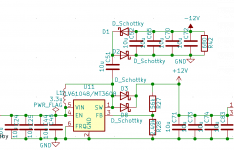
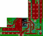
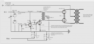
ARC Schematic removed by moderation. This is a clear violation of Forum rules and ARC copyright.

  • Locked
FS: FN1242A DAC

Hi, I have ordered this DAC1242-1.5 "Fluency DAC" in Japan once just to get to know the special FN1242A but I was involved in various projects with FN1242A almost simultaneously and completed this one but never used it. It has 2 BNC inputs that are switchable, LME49860 opamps and Haufe studio 1:1 transformers. It sounds excellent and more musical than a few other DACs I have here. In listening tests some mention the sound character to be warm. I just think it is a very good DAC. As you can see it is chockfull with Black Gate caps.

FN1242A is a kind of special DAC chip made by Niigata Seimitsu who normally produce medical electronics. The chip was used by Luxman in flagship devices.

Make me an offer via PM. It can be bought without casing.

Attachments

  • IMG_2463.jpg
    IMG_2463.jpg
    1,016.6 KB · Views: 497
  • IMG_2466.jpg
    IMG_2466.jpg
    969.1 KB · Views: 479

Unison Research SR-1 schematic/service manual

Unison Research SR-1 Hybrid Tube amp troubleshooting/help

Hello

Have one of these amps that needs some troubleshooting as it passed onto me. There seems to an array of fuses missing once the top cover is popped off for different supply rails from the secondary windings to the output stage/preamp boards.

Anybody here have a schematic or service manual or complete internal shots would be great (the pictures on google are not sufficient for troubleshooting).

Regards,

Amanero into Ian Canada's i2S to Simultaneous PCB, no fS higher than 96kHz

Hi All,

I am using an Amanero PCB feeding IanCanada's i2S to Simultaneous PCB feeding two TDA1541A's.

I was using a DIYINHK PCB (which worked perfectly up to 384kHz) but this failed and the friend who I built the DAC for asked if an Amanero could be used.
The Spec's seemed as though it should but I cannot get it to work above 96kHz.
The three LED's still light at 176/192 but the Audio is distorted.
The i2S LED goes out at 352/384
The BCK coming out of the Amanero drops in Amplitude at the higher fS's so I am wondering if this is the cause. If so, any thoughts on buffering this ?

Ian says he has run his PCB with an Amanero OK.

Any thoughts appreciated.

P.

Zener diode going bad on negative supply voltage

Dear all,
I have a 4*2030 circuit in which I am experiencing a problem that the Zener on negative voltage stops working or the voltage across appears to be 0 and I have observed in all these cases the op-amp ic 4558 I have used also stops working and if I change all of the 4558 and Zener the circuit starts working fine.
I am unable to find the issue why is only the Zener on the negative side causing the problem.

Anmol Malhotra
Student

Attachments

  • Screenshot 2021-08-17 090925.tif.jpg
    Screenshot 2021-08-17 090925.tif.jpg
    327.9 KB · Views: 92

bmw logic7 tda1562

Hi, I have an issue. Amp is Logic 7 hifi it has 2x tda1562sd chips for woofers. Cause of old age 4 Lift supply caps 10000uf has been dried and destroyed integrated charging circuit on TDA1562 (I believe). Strange but it play bass but not good- clipping audio not stable bass. So I decide replace all 4 caps. Sound was great 2 min 😀 and the same story. I have checked new caps dead... Seems chips destroying caps it self. Does anyone has the same experience? I am right?

As we know mission impossible order original chips only fake from CN but I did try and order 2 chips, replace them and no bass at all now...

thank you

tda1562sd BMW Logic7 issue

Hi, I have an issue. Amp is Logic 7 hifi it has 2x tda1562sd chips for woofers. Cause of old age 4 Lift supply caps 10000uf has been dried and destroyed integrated charging circuit on TDA1562 (I believe). Strange but it play bass but not good- clipping audio not stable bass. So I decide replace all 4 caps. Sound was great 2 min 😀 and the same story. I have checked new caps dead... Seems chips destroying caps it self. Does anyone has the same experience? I am right?

As we know mission impossible order original chips only fake from CN but I did try and order 2 chips, replace them and no bass at all now...

thank you

IPC 1028 Preamp Power Supply Build

Hello All,

I was looking to purchase an old IPC 1028 preamp and add it to my system as a preamp. Problem I'm running into is that I cannot find a schematic for the life of me.

Here's a link to one for sale on eBay if you want to take a look. Any idea on how I'd go about crafting a power supply for this?

Thanks in advance for any light you're able to shed on this, I don't imagine it would be terrible difficult but just don't have the technical know-how to craft one myself without a schematic as guidance.

Yet another anthology build

After much deliberation I finally decided to build some Anthologies in December of 2020. ~6 months later I'm finally finished. This was my first tower build and it was quite a challenge. Build pictures attached (more in next post).


I botched the paint job pretty horribly on the front panels so I just rigged some grilles. It worked well.


I've been listening to them now for a few months, fully broken in and just completed the setup with an I15 Prisma from Primare. I'll post my listening impressions very soon. TL;DR: Pretty amazing. Enjoy the pictures!

Attachments

  • 1.jpg
    1.jpg
    124.7 KB · Views: 315
  • 2.jpg
    2.jpg
    151.1 KB · Views: 302
  • 3.jpg
    3.jpg
    145.6 KB · Views: 295
  • 4.jpg
    4.jpg
    91 KB · Views: 298
  • 5.jpg
    5.jpg
    109.4 KB · Views: 313
  • 6.jpg
    6.jpg
    92.3 KB · Views: 176
  • 7.jpg
    7.jpg
    336.7 KB · Views: 188
  • 8.jpg
    8.jpg
    112.3 KB · Views: 199
  • 9.jpg
    9.jpg
    101.3 KB · Views: 199
  • 10.jpg
    10.jpg
    101.2 KB · Views: 282

help with WinSD

I had this subwoofer set in WinSD for a while.
In the process of building a 9.2 C/f box for it.

Went back to try and review the port sizes and options and I some how messed up the paraments in winSD.
its telling me i need an 11,000 c/f box now..

can anyone put this sub in correctly and maybe share the file or screen shot for me.
No idea what is messed up and tried to add it again. and it's still not getting me set right.


thanks in advance.

Attachments

  • Untitled.png
    Untitled.png
    23.9 KB · Views: 162

3 Chamber Single Reflex Bandpass Enclosure

I purchased 2 Stereo Integrity SQL-12s & I'm awaiting their arrival. I was planning to try them in a 3 Chamber Single Reflex Bandpass enclosure with both sealed chambers @ 1 cuft each & 4 cuft for the ported chamber. I've been told to tune between 45 - 55 Hz. I'm using a round port as well. WinISD gives some funky results using 2:1 ported/sealed ratio. Can anyone check & post their findings using this ratio in this type of enclosure? If needed, I currently have 2300 watts RMS I can supply them with.

Dummy resistor for Class D no load protection

Hi

Now i am moving towards the trend of using class D rather than my all time favorite and outdated LM1875 gainclones ... as far as i know class AB amplifiers can tolerate no load operation but for class D i've learnt from mistake through damaging the zobel resistor on my TDA8950 module ...

this time round, ive thought that what if i insert a 560ohm 10W or higher resistor at the output? when there is no load connected or bad enough for the speaker leads to be disconnected by accident with signal on during playing will the dummy load 560ohm tame the high voltage generated by the LC tank on the class D output? if make sense the dummy load resistor gets hot i might locate a heat sensor on top of the dummy resistor if it does get hot during the case of no load it might trigger a protection circuit to mute the input or to shut down the amplifier all together? That day having a friend of mine to install an amplifier speaker setup only realize he use only one channel instead of two lucky it was a conventional class AB amplifier.

i posted this question due to i might build a few class D amplifier to sell to close friend of mine which was not really electronic and amplifier well understood. i know this is common sense that really it needs a load for class D not to run into damage but some others might not know.

thanks

Stacking SiC Schottky diodes

So I have been reading this thread:

https://www.diyaudio.com/forums/tubes-valves/54603-sic-schottky-rectifiers.html

Is stacking SiC Schottky diodes allowed?

I bought some STPSC2H12D from ST. The datasheet doesn't seem to mention this.

https://www.farnell.com/datasheets/2290164.pdf

On one of my amp, the maximum secondary is 520-0-520V. I planned to stack 3 of them.

If it is not allowed, stacking with other types of rectifiers, silicon or tube, is acceptable?

Parasound HCA1500 Power Switch

Looking for a replacement part number for the HCA1500 Main Power Switch.
It appears that mine has decided to get very vibration sensitive. By the time I open up the unit to attempt a Deoxit wash, it would be just as fast to replace it.


I've previously performed a major upgrade on the internals that included the relays and all has been performing with no issues for months.


Thanks in advance.

Piezos in a high power system - How?

Before we get started: I have started down the correct path of crossovers and HF drivers and I HAVE NO INTENTION OF DOING THIS!
so any answers saying that you shouldn't do it are - well dumb, BUT since I was thinking about it and couldn't find the answer I'm going to ask about the science anyway.

Assuming a high power system incorporating at least one conventional LF driver in parallel, how would you add piezo(s) in such a way that they wouldn't blow? I know that you should add a cap to raise the frequency but there is still a lot of energy to absorb. You might need more than one to balance the system.
So; Technically; how should it be done?

Unison Research S9 biasing problem!

Hi, i got a Unison Research S9 integrated amplifier, recently my amplifier suddenly muted when listening to music half way, then i switched it off, waited for around 30 minutes and switched on again, to my surprise this amp can be played lik usual, but i found the V2 bias no longer available, i pressed all the Valve bias switch, V1, V3 and V4 is normal, but V2 shiw nothing, i even tried to adjust the V2 bias, but stil the same. Would like to ask what is happening to my amp, will it be the V2 damaged, hope any sifu can hep me on this problem!

New amp rack for bins only unsure of settings

Hi all,

Its been a while since I've put together a pa set up was retired basically. Covid brought back my love for audio, now heres where I'm stuck, I have a behringer autograph with sub out, an alesis 3630 compressor that I will use for protecting the signal from blowing my bins, and a peavey cs 4000 amp which will run my twin 15s reason for this is the tops are rcf active.

So any advice I would appreciate. Currently I was looking at cutting the subwoofer point at approx 85hz - 90hz.

JL Audio 500/1 Power Light Stays On

I have a JL Audio 500/1 Rev 3 that power light stays on. I have the signal sense switch off and the power light turns on with only positive and ground connected to the amp. It draws no current from my power supply and after I remove the positive from the amp it takes a few minutes for the power light to go off. The amp works fine besides this weird issue. I wondered if anybody has seen this before I spend hours tracing this down. It seems like its taking the b+ filter capacitors forever to discharge which is keeping the light on. But the power light shouldn't turn on with only positive and ground connected to the amp.

Thoughts on newbie design for 2a3 pp with interstage phase splitter?

I inherited some spare parts, including a pair of Lundahl 1660s/18ma interstage transformers and the output transformers from an old Harman Kardon a500. I drew this design hoping to use those parts, plus gas regulator tubes because they look cool.

Will this even work? Forgive me, I don't really know what I am doing! (though I feel comfortable with electrical safety...)

Attachments

  • one_channel.png
    one_channel.png
    222.1 KB · Views: 606
  • ps_stereo.png
    ps_stereo.png
    145.8 KB · Views: 480

Unison Research SR1, no output from preamp?

I'm a total newbie when it comes to gear with valves so please excuse my lack of knowledge.

I have a Unison Research SR1 which is an "integrated" amplifier where the preamp has a pair of ECC82 and the power amplifier is a MOSFET amplifier. The SR1 has been sitting for somewhere between 10-15 years.

Now, turning it on it never goes out of the preheating stage. I can barely see any glow at all from the valves. If I turn up the volume I do get sound out of the amplifier but it's really really really low.

So my question is, should the ECC82 have a visible glow when functioning normal? And have anyone here an idea for how long a preamp with ECC82 should be in a preheat mode? Lastly, since I do get sound out of the speakers even though it's maybe around one 100th of what's normal, should my first try be to replace the valves?

Thanks!

Thoughts on Horn Pressure Drivers for PA such as TOA TU-631 / TU631M / TU651 / TU651M

Thoughts on Pressure Drivers for PA such as TOA TU-631 / TU-631M / TU-651 / TU-651M?

Hi Everyone,

I'm looking to buy some replacement pressure drivers (1 3/8" thread) to replace two damaged Vitavox GP1 pressure units and connect to the existing horn speakers that I have. This is for a temporary external public address set-up for a community fair.

I have heard that TOA is a very reputable company with decent products, and notice that they have several reasonably-priced drivers such as the TU-631, TU-651 and their corresponding constant-voltage equivalents, the TU-631M and TU-651M - see here:

TU-631 | TOA Corporation

Does anyone have any experience of these, or have any recommendations for alternatives (bearing in mind that I am looking for an inexpensive solution for temporary outdoor public address)? A lot of people seem to be very strong advocates of vintage Vitavox products, so will these be radically different (for better or worse) or perfectly adequate for my purposes of background fair music and occasional announcements?

Thanks in advance for any help - some of you might have seen another thread I created yesterday on speaker layout on a field, and as people were so helpful I though I would try my luck again!

Many thanks,

Andy.

protection mode takes days to clear?

Hello

I have a primare a30.2 amplifier. when it goes into protection mode it takes days to clear.

I build my own speakers and the cross overs are naked. I found a loose capacitor in the crossover that I suspect caused the amp into protection mode. The first time the amp went into protection mode while playing music at a moderate volume and restarted after 12 hours the second time was a very low volume it is still in protection mode after 24 hours.

on a previous occasions the amp went into protection mode for unknown reasons loud volume it took about 3 days to clear the protection mode. I have suspected the speaker cable but it could be something more serious.

So my questions are: is the long time to clear the protection a symptom of a bigger problem? The drop of grease on the temperature sensor attached to the heat sink was running down the heat sink is this a sign of overheating? the amp did not seem excessively warm when the speaker quit the last time. just out of curiosity is the long time to clear the protection mode a capacitor that has to discharge before the the protection mode resets? is it a bad relay that is causing it to take so long to reset?

attached is the service manual

thank you any help would be appreciated

Attachments

Help troubleshooting Maida regulated supply

In the last week my stereo SE PCL82 kitchen amp developed 100Hz hum after >1 year of solid use, sometimes many hours a day. I'm looking for some guidance on likely causes / troubleshooting methods before I fall down a rabbit hole of trial-and-error despair!

Schematic attached.

Symptoms:
  • 100Hz hum (verified by basic FFT) in both channels starting a couple of minutes after power is applied.
  • Normal audio heard prior
  • System otherwise normal
Background details:
  • This is my PCB based on a design by Merlin that has been used successfully by others.
  • I had an issue with thermals - without heatsinking (or even with it on very hot days) an audible 'throbbing' would occur intermittently. I moved the MOSFET and LT regulator to opposite sides of the chassis, with external heatsinks attached.
  • Has worked (other than the throbbing on hot days) for over a year without trouble.
Steps taken so far:
  • Visual check of PS caps - no bulging
  • Visual check of off-board connections to the MOSFET / LT Regulator - all seemingly OK
  • Replacement of valves with a new set - no change
Tools I have to hand:
  • Scope
  • Multimeter
  • Freeze spray
The HT regulator supplies 0.05A @ ~280VDC.
The LT regulator supplies 0.6A @ ~14-15VDC.

My initial thought is to replace the HT MOSFET Q2 and regulator U2 - as if there was any failure to regulate properly, the ripple on the HT would pass from plate -> speaker.

Any ripple on the LT side might be less audible - like normal AC heaters?

If it is a temperature-related failure, freeze-spraying should show that up? Or would cooling the component cause other issues?

I'm slightly nervous of scoping the HT line given it is close to 300V (which I think is the limit on my scope's input). But I do have 1000:1 probes if that would help spot where the problem starts.

Basically, I'd be grateful for suggestions of a methodical approach to fault diagnosis, Pease-style.

Attachments

  • RegulatorScheme.png
    RegulatorScheme.png
    293.3 KB · Views: 302
  • IMG_0388.jpeg
    IMG_0388.jpeg
    444.5 KB · Views: 295

FS: USB Virtins DSO and Hantek Function Generation

Hi,

Up for sale two USB instruments, fully functional and in good condition.

- Digital Storage Oscilloscope: Virtins VT DSO-2815H. Two channels, 8 bit resolution, 150 MHZ sampling rate, 50 MHz bandwidth. Built-in license dongle.

- Arbitrary waveform generator / Function Generator / Frequency measurement / Event counter: Hantek DDS-3X25. All usual and advanced functions of this type of instruments.

Both are powered by the USB connector of the PC they are connected to. Both work with all Windows versions XP and above.

These are great for audio work, particularly for measuring transient / frequency responses, and capturing random glitches.

100 EUR for both. Shipping is 8 EUR in Europe, or 15 outside Europe. USD or PLN also possible at the spot exchange rate. Payment via Paypal F&F or bank transfer. Local pick-up also possible.

Thanks!

Attachments

  • USB Instruments for Sell.jpg
    USB Instruments for Sell.jpg
    645.7 KB · Views: 156

Oracle Premier Turntable speed controller

I recently bought an Oracle premier with a Tri-Planar tonearm. 30 years old, price was right. Well, almost right. There was no speed controller with the turntable. Thought it might show up at a later auction, but no luck.

The motor has a seven pin plug coming off of it. Can anyone build me a 33 rpm controller for this turntable? Can an existing speed controller from any number of other turntables be modified (hot-Rodded if you will) to run this turntable?
Otherwise I have a nice piece of sculpture.

These controllers are none existent unless one of you knows of one for sale.
Thanks for reading. Any and all help is greatly appreciated

Change 230 V to 115 V power transformer

I have a Bose AM-8P Acoustimass speaker system that I bought in Europe. It continues to operate fine in the US if connected to a large external step-up transformer. I want to use it without the external transformer (which creates a hum and wastes energy). Can't I just replace the internal 230 volt power transformer (Billion #192252) with a 115 volt power transformer (Billion #182577)? If the answer is yes, then how could I locate such a transformer? No luck so far finding one on-line. Or is there someway to re-wire the 230 volt transformer (which has 5 primary wires leading into it and 5 secondary wires leading out of it -- I can send a photo once the server cooperates)?

I asked Bose customer support and they wrote back that "It is not possible to internally transform this unit to 120V by installing a 120V power supply. Bose does not offer power supply conversions on this product, and the internal parts of the product are not available to be purchased by end consumers for self-installation."

Thanks for any advice.
Projects by fanatics, for fanatics
Get answers and advice for everyone wanting to learn the art of audio.
Join the Community
507,909
Members
7,893,272
Messages

Filter

Forum Statistics

Threads
406,471
Messages
7,893,272
Members
507,909
Latest member
BenM74