New Crossovers with Hz/db switches & DIY speakers

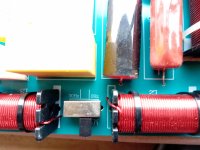
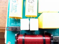
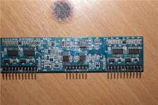
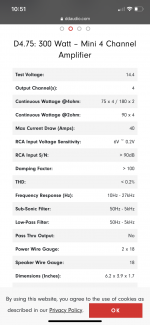
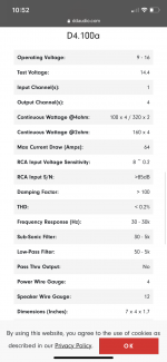
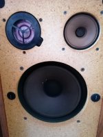
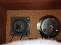
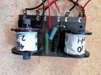
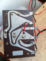
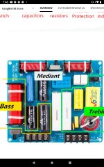
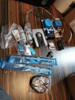
Hi I just received these crossovers today I realize it's not ideal for my set up but until I get some different ones I'm wondering what these switches are for there are switches for each for the following as in pics.

0Hz-30Hz for bass
0Hz-30Hz for mid
and a
0db to 3db for treble

The mid to treble crossover frequency on this crossover is at 3500 KHz but after much searching and emails I have been not been able to determine the bass to mid crossover point on this crossover. I think it's around 2500 KHz would anyone happen to know for sure?
TimScreenshot_2021-07-06-19-46-28-075.jpeg

IMG_20210715_114234_885.jpg

IMG_20210715_114304_165.jpg

Maximizing Subwoofer system "throw" - Excursion vs cone area.

Guys, I thought I was sure about this, but no longer so, and I REALLY need to know for sure:

This isn’t a question of sealed vs ported vs TH vs FH.
And this DEFINITELY is not a questionn about SPL. - I have found countless threads about that.

For this thread, I’m concerned only with LF “throw." My definition being: The ability for a sub system to maintain as even an SPL level as possible over distance. For this discussion, let's say from around 10 feet to 100 feet. (I do small gigs.) I have always been of the opinion that total cone / port / horn mouth area is what matters. (More speakers at lower volume each.) Other people seem to think that cone excursion & total dispersion are all that matters. Or maybe it’s displacement, but it's the same result in that case: Less speakers with more power to them / more excursion.

(Again, this is not a discussion of ported vs horn loaded, etc.)

Here’s the simple setup / question: (I know this is fairly obvious, but I want to be sure we are discussing exactly the same thing.)
——————————————————————————————

Take three of any subwoofer you like, and set them up with a pair of decent tops. Tops that should carry well over the same 10 - 100 feet test range. For this test, put the tops right next to each other, and not too high.

Run your amp into sub “A” by itself, and get its output balanced with the tops.
Also test with a meter.
Now listen at 100 feet and note how much apparent loss there is.
Also test with a meter.

Now repeat this test, except with both sub B and sub C running, (No sub A) but with the subs amp turned down, so the tops are still balanced.
Also test with a meter. At ten feet, I would assume the subs’ spl level will be very close to the first test.

OK, so at 100’, is there any difference in balance / in subwoofer spl?
Based on my own (limited) experience, and just using my ears, there will be. Test #2 will give noticeably more LF at distance.
- But some pretty intelligent guys disagree with this, so it’s driving me nuts. Especially since this is driving the design theory behind my new subs system build.

What say you? And why?


My theory, assuming that my ears are not fooling me, or that it has something to do with small room nodes and compression, is thus:
If you can excite more air molecules at the source (the subwoofer) but use less energy per molecule, then the less loss there will be as the waves travel through the air.
That just makes sense.

The guys that disagree say that more cone excursion creates just as much dispersion, thus just as many air molecules moving.

My counter to THAT is, even if it’s true (I don’t know) there is more energu behind those molecules, thus higher resistance through the air, yada yada yada….

Am I wrong?

I’m planning on building four smallish subs, and running them at “medium” power, instead of two equal subs pushed really hard. This gives the advantage of using lower-powered and hence more sensitive drivers. This also may have a small advantage is sound quality, due to less excursion. - But that doesn’t matter for this discussion. I just want opinions on the issue of “throw.”

thx.

Converting active subs to passive query

All the cheap amplifiers in my H/T speakers are on the way out, several have died already and these cheap amps seem to not worth repairing even if the faults are minor.
I'm considering biting the bullet and converting them all from ported active to simple sealed passive.
I have no data for the drivers and still no test gear apart from the multimetre but the 12" are reasonably sized magnets with about 8mm of travel P2P and the tens are a very common generic with bigger magnets and lots of travel
Pix later.
Had these for a dozen years or more so I've got my monies worth from them but I see no need to trash if I can make them work passive.
Any tips; hints; pitfalls; advice for me before I start?
It will mean I have a dozen small toroid transformers [ maybe 150- 200VA] and associated heat sinks here that may have some small value

Crossover accessories terminology help please

Hi guys,
I need help with choice or terminology of speaker crossover parts.
I have all the drivers, capacitors, coils and resistors.
The crossover will be quite complex so I want to figure out layering and connections between the components. It will by trial and error, thus I want to avoid much soldering at first stage.
Can not find anything useful on internet as I am not using proper terms.
I want to connect wires to wires - multiple or single “input” wires to one or more “output” wires.
Initially I had an idea of grouping of cheap russian PETP capacitors (I bought already) instead of using single high value (15,33,56,220 and 600uF) expensive PE caps.
At the end, I also bough those higher value caps in form of bipolar caps, so that will be first step, and maybe sufficient.
There should be some kind of buses/ rails available to connect more caps/ components into one output..
Thank you for the suggestions.

Slots and Dados vs just glue?

As part of a woodworking forum I asked an opinion of what a slot/dado would do to help a cabinet vs just glue. Of thos who replied, a glued joint is as strong or stronger than MDF itself. The tritrix has slots cut appx 1/4" into the sides for the TL divider to fit into. The corner waveguides do as well. So My question is of how important is this joint if the divider is well glued and clamped just to the surface. Also, the slot/dado does not run the full length of the TL. Both ends have appx 4 to 5 inches that come up out of the slot/dado and glue to the surface.

The search feature here turns up threads with hundreds of pages and no way that I know of to find the exact info so I am asking this in here as well.
.
.

Attachments

  • cab3.jpg
    cab3.jpg
    98.2 KB · Views: 269

Help recommending a preamp that is 5.1 but has 2.1 or extended stereo functionality

Hi!

I'm a complete beginner in the topic, I have a cheap 5.1 system with a broken amp (and it was equipped with a rather overly complicated preamp), and I thought I'd give a try to replacing the boards and give some update to the system, since I like the speakers.

My main concern on the preamp is that it should have a 2.1 functionality (where the sub plays the bass frequencies in mono) or an "extended stereo" functionality, by which I mean that left front & left surround play left, right front & right surround play right, sub plays low frequencies mono, center is either mono or silent. This would be a dream, but I'm completely fine with a 2.1 mode.

I've found some cheap Chinese boards (AIYIMA NE5532, AIYIMA NE5532 5.1 Tone Preamplifier Board HIFI 5.1 Preamp Volume Tone EQ Control Board DIY for 5.1 Amplifiers|Amplifier| - AliExpress) that look good, they have 5.1 and 2.0 inputs, but I don't know how do they behave with the 2.0 input. Can somebody that knows this kind of preamp tell me what happens if I connect a 2.0 input to the aux-l and aux-r? I see no switch to switch between the inputs, and my concern is whether this input would only be played in the stereo speakers, or the bass would go to the sub?

I also have a transformer leftover from the original amp, which has dual 11V, dual 12V, and normal 10V ac outputs. I've measured the 11V to be 12V+, is that enough for this preamp?

In case you know a preamp that meets my expectation and is in the price range, please also share.
Thank you!

Free Large Toroidal Transformer 140 vac +50+40

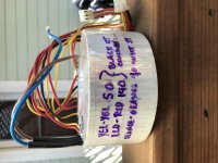
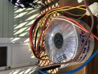
Free transformer for anyone who wants to pay the shipping. It is big! I bought it to possibly repair a Hafler power amp but ended up not needing it. It was supposedly out of a big Arcam power amp. It looks to have 140,50vct plus a seperate 40vct. I don’t know the current ratings.

Shipping is $22.00 in flat rate box US only.

Attachments

  • BA7FB2ED-2F93-4E7D-9BD9-750B04E28F2E.jpg
    BA7FB2ED-2F93-4E7D-9BD9-750B04E28F2E.jpg
    790.7 KB · Views: 183
  • 5E9AA44B-1395-4F28-BF0D-0C5F79E294D4.jpg
    5E9AA44B-1395-4F28-BF0D-0C5F79E294D4.jpg
    806.9 KB · Views: 168

The Advantages of Floor Coupled Up-Firing Speakers

:cop: Note: Thread title changed.

Reading what many people in audio wrote on the subject of loudspeaker design (Carlsson, Beveridge, Moulton and Linkwitz were my main inspirations) I came to the conclusion that the real issue is that loudspeakers and room form one system.

Recently I had an impression that this I also a view of gedlee (Dr Earl Geddes) when he wrote that the most important parts of his book are those concerning waveguides and room acoustics ("Don't read the stuff on non-linearity, but fully grasp the chapter on waveguides. Thats what I would say today.That and room acoustic")

Later I came to believe that what Dr Geddes writes on the topic of room reflections is in the end of the day the same thing that Carlsson, Beveridge or Moulton and also Linkwitz have written on the subject. And that in their designs they wanted to achieve the same end - to eliminate the detrimental effect of room reflections.
And yet their designs are so much different!
Apparently there are many ways to achieve the same. Linkwitz’s experience with subjective evaluation of his own an yet very different dipole and omni designs confirmed this for me.

I have very unusual loudspeakers which I have built some time ago with those room-speaker interface things in mind. These are very short omnidirectional loudspeakers. They are just 20 cm high and have 8 inches wide range driver on top and firing upwards.
The loudspeakers are to work on the floor – the driver is only 20 cm above the floor – and against the wall.

In this positioning they happen to be quite similar to the late Stig Carlsson designs (carlssonplanet.com, but the Carlssons are two-way and much more complicated because of that) but were not inspired by them.
I didn’t know the Carlssons when I was building these and my first and main aim was to eliminate the detrimental effect of early floor and ceiling reflections without resorting to unavailable true linesource (like Beveridge)
The second aim was to build loudspeaker least visually obtrusive, loudspeaker that would be practically invisible in the listening room (which in may case at the time was also a living room). Perhaps it was even equally important goal.

But frankly speaking I wasn’t thinking a lot and I think now that I really didn’t know what I was doing 😉 and still I don’t – I have no technical background – and it was and it is all mostly intuitive. 🙂

But the outcome appeared to be quite satisfying. This is still work in progress. Achilles heel of the loudspeakers are 8 inches Fostex wide range drivers which have major resonant problems in the break-up area. Out of the box they were literally howling at me. After some driver-mutilating (i.e. tweaking) I can say that these problems are only partially solved for the time being and I am looking for a different driver

Soon I will have a new listening room that is 350 cm wide and 550 cm long. Not too big and not the best proportions but I can arrange it specifically for audio purposes.
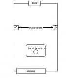
I am considering positioning the speakers against the opposite longer walls (scheme attached). Stereo basis would be 330 cm. The listener is to be located 200 cm from stereo basis, 250 cm from both speakers

All this with the questions of minimizing early reflections in mind and particularly with what Dr. Geddes has written on this forum.

A big thanks goes to Dr Geddes! 🙂

To my not very big surprise the resulting set up happens to be very much like Beveridge positioning of his line source electrostatics.

The positioning would give very early reflections (VER) <1 ms from adjacent wall. I hope that they would not be strong enough to become audible problem because the Fostex is quite beaming (I don’t know for sure but 8-inchers are typically 7-8 dB down at 1 kHz at 75-90 degrees and 12-15 dB down at 2 kHz). I am also considering using small Carlsson style absorbers effective for midrange and high frequencies as an option.
Apart from those very early (and hopefully low in level) VER I expect that:
- significant reflections off the adjacent wall would not reach the listener
- floor reflection would not reach the listener
- first reflections off the front wall and off the back wall would reach the listener 9.3 ms after the first wavefront
- first reflections off opposite walls would reach the listener 8.3 ms after the first wavefront
- first reflections off the ceiling would reach the listener 8.8 ms after the first wavefront (ear at height of 90 cm, ceiling at height of 300 cm)
It seems that apart from those earliest reflections <1 ms all other reflections are delayed more than 8 ms and caught by proximity (Hass) effect.
And all this in a relatively small listening room. The bigger the better.
Also I am considering using some wide band absorbers to reduce the reverb after first 50 ms as Moulton recommends.

What do You think? Any suggestions? Ideas? Your own unusual setups?

best,
graaf
Attachments

  • room.jpg
    room.jpg
    10.3 KB · Views: 13,937

Genelec 4020B input connector? (Green strip type)

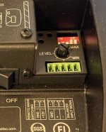
Does anyone know the Mouser/Digikey part for connecting the signal inputs to a Genelec 4020B? Image below.

Its one of those green strip euro types, 5 contacts.
There are so many variations it boggles the mind, figured someone out there would know.

Image (found online) attached, looks just like this.

Attachments

  • genelec 4020B No. 1.JPG
    genelec 4020B No. 1.JPG
    66.7 KB · Views: 123

FS: Ian Canada digital gear - LifePO4, FiFoPi Q3. Plus Pi2AES

Hi all, have some things to sell. If it's allowed, I'd prefer an email to trvtec@gmail.com over a PM just because I haven't been frequenting the forum recently but either way should be ok if PM is better for you.

I have the following for sale:

Ian Canada LifePO4 Mk III
An externally hosted image should be here but it was not working when we last tested it.

Includes a Dell 300W power supply for charging, as well as 10 26650 batteries. Not willing to piecemeal this. $275 plus shipping to the US.

Pi2AES
An externally hosted image should be here but it was not working when we last tested it.


An externally hosted image should be here but it was not working when we last tested it.

- early revision of this streamer. Does not come with any extras, no power supply. Requires 12-19V, can power a Pi3 or Pi4 with one PSU. $100 shipped, US only.


Ian Canada "Digital to digital converter" with USB in, i2S out. Rates up to PCM384 (8x) and DSD256 are supported. AccuSilicon clocks are included, as are the standard Ian Canada oscillators. Will not seperate. HDMIPi is modified per Ian Canada instructions. Requires power supplies in accordance with Ian Canada documentation.
Includes:
Amanero Combo384 USB receiver
FIFOPi Q3 reclocker with AccuSilicon 90/98 oscillators
HDMIPi mk1 modified
$275 shipped for everything, US only. This is a little hard to get pictures of without taking it all apart (which I'd rather not do). If more pics are needed, I can try to get better ones.
eVpe5Y6h.png


All Ian Canada and AccuSilicon items were purchased this year from audiophonics.fr. Pi2AES is currently backordered, but I bought it new from Pi2Designs a couple of years ago.

My email is trvtec@gmail.com. Paypal only please. Prices include fees.


EDIT 9/8/2021 - All items have been sold. Thank you!

Nakamichi AV-10 - No/Limited Volume

Morning Folks...

I already searched for this and its kind of rookie question given the expertise Im reading on the site.

My Nak AV-10 is producing a whisper of a volume from one channel and none from the second. I havent plugged it in in 5 years but I recall both channels were doing the same thing.

I think the power transitors are shot or certainly the final drive section is in need of help. Its just a surround sound system and something I use at low-moderate volume with guests.

Is it worthwhile to fix it?

Anybody know what transistors I need to replace or should I just replace all of them?

Any suggestions on where to get parts or a kit?

(I have no problem upgrading components)

Thanks
Soldering iron is ready to go!

Buzz or Noise in Distribution Amp Output

I have a multi-zone audio distribution system. Each output is 25w/ch and can support 8 or 4 ohm loads. In some rooms, I hear a hum or buzz when the system is off. In some cases, briefly turning the zone on will alleviate the matter temporarily. Doing so often results in a small audible "pop" as if it were relieving pressure at the output. In some areas, this action does not change anything.

I do not have info on the type of amp used. Sources and amps are all on the same power circuit. In my mind, this eliminates a ground loop scenario and points to a cheap noisy amp.

At present, every zone is an 8ohm stereo pair.

Is there something that can be done to bleed off this noise at the amp? Possibly a small resistor across the speaker outputs? Any suggestions?

How do you amplify a speaker level signal?

No hifi, but still 2 channel.... I am looking for a relatively inexpensive solution to a quirky problem. We replaced our security system and failed to consider how the audio events would work through our automation system. We have touch panels at each door and a wired balanced stereo audio feed goes to the touch panel and you hear the audio when you open an armed door or arm the system.

The new panel (Elk M1 Gold) panel has an unbalanced mono output for siren, and a unbalanced mono output for voice feedback. The prior system combined these two signals into an unbalanced mono out and life was great. I jumped the negative and the ground on both channels (if that is relevant).

ISSUE: Audio from the siren feed (the countdown beeps) is almost inaudible. The voice feedback (system is armed) is overdriven.

QUESTION: Assuming this is an amplified signal, is there an inexpensive way to amplify the siren feed? The security panel offers a variable audio level for voice, but siren level seems to be fixed.

Added data point... there is a simple speaker that came with the new panel and when connected to either siren or voice, things sound fine, but the panel is too far away from any of the doors to be useful from that location.

Any suggestions?

FS: Single Ended Output Transformer 5k/25watt

For Sale is a pair of 25 Watt Single Ended Output Transformer made by Heyboer.
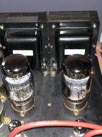
Specs : 5k primary 25 watt, 40%UL with multiple secondary taps 4,8,16,32, 300ohm. This are used and in great condition. This are similar to edcor CXSE 25 watt in specs. Pics are from When they were used in a SE kt88 in UL. This is a very good sounding opt.

Asking $150.00 from 60060. Pls mail me at ivardlr@gmail.com

Thanks

Attachments

  • 56965300-F32B-4563-B9BF-C14D5978AE55.jpg
    56965300-F32B-4563-B9BF-C14D5978AE55.jpg
    546.7 KB · Views: 302
  • B60629AE-5D49-43AD-A8AC-3B9DCD4C9DDE.jpg
    B60629AE-5D49-43AD-A8AC-3B9DCD4C9DDE.jpg
    779.3 KB · Views: 302

First tube amp build - not going too well..

Hi everyone,

i finished my first tube amp yesterday and went to turn it on today but it does stuff it's not supposed to.

The Amp uses 6n1p's driving EL34's connected in Triode mode, i got the schematic from a friend who has experience with tubes and built multiple amplifiers already so i trusted him on that..:

QcrclQH.png


The speaker connected to the left channel emits a continuous popping sound and when applying an input signal it comes out as extremely distorted.
The right channel has another issue, it's quiet at first but then starts emitting a distorted sounding hum that gets louder as the tubes warm up to the point where i have to turn the amp off to not damage my speakers.

I swapped out the tubes but the issues persist so i don't think they're faulty.
I also double checked every connection and wire and could not find any issue.
Here's an image of the guts, i know it's far from perfect:

eMSuJz4.jpg


So yea, if anyone has an idea about what could be wrong please tell. Maybe it's even the schematic itself that can't work that way? He told me he based it on an existing design and modified it..

Thanks in advance!

Logarithmic power VU meter

To indicate the power level, I came up with a small driver for the VU meter


Log-amp-for-SO-53.jpg


The amplifier is a chip for hearing aids. The logarithm occurs on the nonlinear characteristic of the diode chain. At the output, a forcing chain is added, which allows the arrow to move quickly forward and slowly roll back.

Gain characteristic:

Log-amp-characteristic.jpg


General view of the structure with the SO-53 VU meter

SO53-log-top.jpg


SO53-log-botton.jpg


There is one drawback, at elevated temperatures, the driver lies, so this driver is of little use in "hot amplifiers" without its own cooling.

A highly detailed, analytical amplifier for the Beyerdynamic T1?

Good day everyone 🙂,

I'm looking for a DIY solide state amp for my Beyerdynaic T1 that has a high resolution and plays extremely clear, detailed and analytical, preferably together with a holographic presentation - (almost) exactly the opposite of my current amplifier for the T1, a slightly modified Darkvoice 336e, which has its own charm with its warm, nicely colored sound (and a nice holographic presentation), but sometimes I would like to experience the other sound of the T1, depending on my mood.

Do any of you have a recommendation or two that I might enjoy?

Greetings
Mike

Baffle step compensation circuit for bookshelf speaker

Hi Guys, I am building my first bookshelf speaker ever.

To keep my first build as simple as possible, I decided to reuse the enclosure from my old Wharfedale Valdus 200 s(12 Litres) and bought Alpair 10p fullrange drivers that should fit nicely, but by the spec they require a bit more enclosure volume for good bass extension.

I can sacrifice sensitivity so is baffle step compensation circuit a way to go to boost the bass?

I already built the bass reflex prototype, but have to tweak the bass (+8db) via amplifier tone controls to get the bass a like. I would like to het the same result without using tone controls.

I am wondering whether baffle step compensation loss circuit starting at let’s say 100 hz is a way to go.

Many thanks for any hint,
Pavel

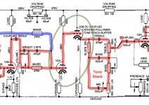
Fender super reverb 1979 strange sound

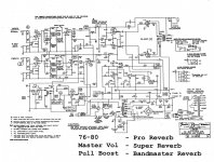
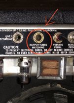
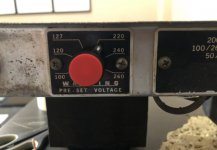
Hello to the forum .. 3 weeks ago a friend of mine brought his amp for repair because it did not work (the amp is a fender super reverb 1979 diode rectifier). when I opened it it made a buzz and the guitar signal could not be heard…. finally 2 tubes 12ax7 had burned and the 1 6L6… also had the hum balance pot damaged and I replaced it .. the 2 12ax7 were replaced and I also changed the 2 6L6 I just could not find jj matched and I got 2 unmatched tung sol… the amp just worked made a buzz .. which buzz I turned off by adjusting the output maching tubes pot, as exactly FENDER mentions in the manual .. the amp was playing perfectly! .. yesterday my friend notifies me and tells me that he started making this buzz again .the amp plays normally, it just makes this buzz .. I told it to adjust the output maching tubes from behind and it will decrease… it did not disappear, it just decreased .. what is wrong? was it the fault of the 2 6L6 that are not mached? Is the main transformer power to blame because it has it at 220v? I say this because the transformer also has a 240v option. and from what I measured the current here in Greece it is 230v…. what could be the problem?

thanks
F65AC630-FCD5-4077-A4D7-F2B8B8048406.jpegFF886052-2290-4144-B2B0-AEF487E494B8.jpeg46FD52E3-FE81-4EE1-8A5C-603226175464.jpeg

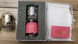
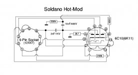
Soldano hot mod

Hello guys … today I saw something very interesting .. there is a patent of SOLDANO for the amps jcm800 and jmp and it is called hot mod. is an adapter that accepts a tube EC10 (6K11) and greatly increases the gain on the amplifier .. put it in place of v2 and ready .. out of curiosity I searched for this patent and found only one schematic .. just looking at it I think it is wrong or am I wrong… in schematic pin 7 (the second grid of v2) has no contact anywhere .. is there a case for the signal to pass elsewhere ??AC1F77C1-F0C3-46E8-8C0A-BA3053A41DE2.jpeg

6F8D4CA6-1A92-49C9-A7E1-78154A33B0F8.jpeg

50CD41ED-1A7F-45D3-8FC7-7E8F04B1FA6C.jpeg

XO slope and why you need DSP

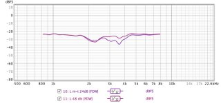
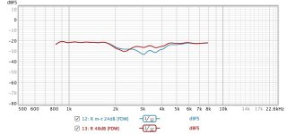
So I was reading about a bleeding-edge Manger speaker where they favour 96dB/8ave slopes. So I thought I'd see if my tweeters should come in at L-R48 instead of L-R24 (only tweeter moved), at 3kHz?

With a DSP, takes about 20 seconds to switch from one slope to the other. Or to change the XO frequency a bit. Or to..... And it takes just 3 seconds to replace the old setting memory with the new settings (Behringer DCX2496).

Attached are L and R systems with the flatter curve in each being the .... you can guess for yourself (or read the labels). Distortion a bit lower with 48 but impulse - at least in first milli-second something of a toss-up.

I just can't understand how a DIY person can be without DSP, even if just for setting up their HiFi.

B.

Attachments

  • Left XO slope.jpg
    Left XO slope.jpg
    92.2 KB · Views: 680
  • R XO slope.jpg
    R XO slope.jpg
    92.4 KB · Views: 684

NE5534, Vcc > +/-10v pointless for 9v balanced output?

Hopefully the title says it all. In the BurrBrown (Ti) document attached the NE5534's are provided with 15v. Another design I've seen uses 12v, while the peak output for balanced is 9v.

The NE5534 isn't rail to rail and requires 1v headroom as a minimum. Therefore, in this application is there any point in going above 10v? As I see it it'll just waste the excess as heat in the op-amp.

Attachments

The Awesome Cordell Amp!

There's a really great amplifier, designed by Bob Cordell.
It's a FET input and MOSFET output.
a description can be found at:
http://www.cordellaudio.com/papers/mosfet_with_error_correction.shtml
I'd like to start a discussion of updating and building this amp.
It's only 50 watts as originally designed, but it should be easily modified to over 100watts just

by raising the supply voltage to 50 volts on the MOSFET outputs and maybe paralleling 2 of them.
(+raising the input supply to 65volts)

I'm not posting this merely to share my own adventures, but rather (i hope) to get a large participation of experiences and ideas.

Soundstream Rubicon 805 repair

Hello,


I have a Soundstream Rubicon805, unfortunately not used for years but it works when I put it away. Now I build a new system in a car and want to use this really good amp, but it doesn't work.
It turn on, power led is on (red) but there is no music, all channels are dead. The positions of the switches doesn't change anything.
So I opend it, threre are no visible damages.
I tried to test the switches, those I could measure are O.K.
If I power it on there are +30/-30 V , so everything seems to be fine.:redhot:

I would be happy for every suggestion to get this thing work.

I coudn't find the schematic's for this amp, I only have this for the 705 but there is a lot of difference in the layout.

System setup question

I have some 8” and 6.5” speakers in my truck both are in front doors .

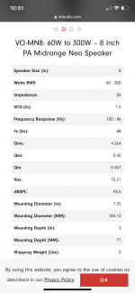
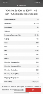
They are suppose to be like PA speakers and are meant to get loud I also have some tweeters in the doors .

I’m running the head unit just below clipping level and adjusting the volume with a Rockford Fosgate Symmertry .

The problem I’m having is the output of the speakers is no louder then what the factory system was .

All my eq setting are flat could this cause the issue ?

My gains are set to about halfway and the output really isn’t nothing to brag about the factory Bose system had the same output

Any ideas ?


All my equipment is digital designs as far as speakers tweeters and amps

I posted the specs for the speakers and amps .

So I don’t really get why the output is low

Attachments

  • F691EC13-DDF2-43FB-BF6B-D3DD1F0AC39D.png
    F691EC13-DDF2-43FB-BF6B-D3DD1F0AC39D.png
    479 KB · Views: 76
  • 94655DF9-294B-44F9-8DDD-7D9FA3F715A3.png
    94655DF9-294B-44F9-8DDD-7D9FA3F715A3.png
    427.9 KB · Views: 70
  • 076A5FCD-2839-424D-A2F1-A5167677279D.png
    076A5FCD-2839-424D-A2F1-A5167677279D.png
    404.8 KB · Views: 73
  • B611267F-8D9C-450A-99D2-68DB8860C9CB.png
    B611267F-8D9C-450A-99D2-68DB8860C9CB.png
    332.1 KB · Views: 74

Digital Panel Meter That Displays Watts

I would like a digital panel meter attached to my bench that displays watts produced by amplifier being tested. I can't find anything where the load is programmable for 2/4/8 ohm load except this:

https://www.velleman.eu/products/view/?id=381888

Otherwise the meters I've seen use a clamp to measure current...that's not what I want.

Is this too much to ask?

Dual SE amplifier? - (not PSE) - Take two!

Sorry Shane, but your thread got messed up somewhere along the line. I find your original suggestion interesting, so hope you don't mind we try again...

There were many good replies untill all the 'my amp is better than your amp' started coming...

Please folks, absolutely no such 'I find SE sound worse than PP and OTL is really the best...etc etc'

Lets keep it to the factual design issues eh?

Ceglar wrote:
Dual Single Ended Amplifier? - (not PSE)

--------------------------------------------------------------------------------

Hi,

Wondering if anyone has seen, built, or heard anything like this..

Two SE output stages per channel, signal at each grid out of phase WRT the other. Two SE output transformers per channel, one of which has its secondary winding reversed so that the waveforms are recombined in phase.

There are some interesting things that supposedly occur in that there is a combined function of the two output transformers.

All of which is outlined in the diagrams and description at;
Dual single ended amplifier by Cohen, Graeme John ? AU1996042023

I'm interested in pretty much anything anyone cares to offer in response.


Thanks,
Shane
-------------------------------------------------------------------------------

The problem with the above is the inverted secondary of one of the SE OPT. The response of a transformer when the 'dots' are connected in phase is not the same as when connected out of phase. Must be b/c OPT are not wound 100% symmetrical, and Pri-Sec leakeage capacitances and inductances are exagerated when the windings swing opposite of each other.
(Kind of like how miller capacitance is actually the static capacitance times the gain(Cgd in FETs or Cgp in tubes - u get the picture)).

How ever, if connecting the outputs in a bridged config, hot positive and hot negative phase, then it should work just fine. Impedances must of course still match, but most OPT have 4,8, and 16ohm taps, so shouldn't be the greatest problem.

Bel Canto made an amp like this some 15years ago: Bel Canto SET 80 monoblock power amplifier | Stereophile.com

I am almost done with a guitar amplifier using two SE OPT b/c I ran out of PP OPT and have tinkering about this idea for years. So this Summer I desided to try it out. Hope to have it finished in a few weekends...

I am building it as a class-AB amp, which means I will let each phase run at about 15watt idle (5881 tubes) and one phase will cut-off while the other goes 'more-on'. That way I will get more power compared to simply running two pure class-A SE in bridged mode.

0.5C/W heatsink for TO-247 ?

i am in need of a heatsink to go on top of a chassis. Its for a TO-247 mosfet. specifically one running at 24vdc and 2.5A.

I would like a 0.5C/W heatsink if possible. I have been looking around and for whatever reason having a hard time finding one. I would of course have to tap a hole to mount the device on the heatsink.

Any help would of course be appreciated.

How effective adding an angle to the side at strengthening an enclosure

A rectangular cabinet is strongest at the corners. The sides act as a brace. To some extent adding an angle/side to the enclosure should have the same effect. I assume that this has been studied and can be shown mathimaticly. However, my Google skills have failed me. Does anyone know of a calculator for this type of thing?

My current example of what I am talking about is building a speaker 30" h x 14" w x 12" d. If I were to miter the side panels at 6" back from the baffle so that the back of the speaker were smaller how much would this make the side panels stronger/stiffer?

Elelkit TU-8500DX Channel Imbalance

I bought a used Elekit TU-8500DX. It sounds fine except for a 2-3 dB imbalance in the levels between the left and right channels. I replaced the tubes but that had no effect. I assume the problem is an asymmetry in the potentiometer or a slight mismatch in the resistor values in each channel. I'm guessing the easiest fix would be to replace the R38 100K Ohm resistor with a slightly higher value? Can anybody tell me if that is the right course of action and how much I need to change it to get a 2.5dB reduction in volume in the right channel?

Box Tuning Question - Faital Pro 18HP1030 / 18HP1010

Hi,

I am seeking a response from the experts here.
In the quest to build DIY sub, I have been exploring 18 inch drivers which fits my requirements - which has greater xmax (i.e. above 12 min) to allow deep low end below 20hz in my 450 sq feet hall.

When I explained my plan about DIY sub to local dealers of faital pro, I was told not to build enclosure below the resonance frequency of the driver (Fs) as technically the driver wont be able produce signal below Fs. Although I explained the winisd simulation suggests it can produce signals below 20hz at higher SPL, he is not convinced about my decision. Also he strongly suggests to match it with min 1000w power rather than 500w which I believe would be more than enough for home usage.

Is there a problem in tuning enclosure below Fs for these drivers?
Does it really needs 1000w amp as I was told I would clip the amp with 500w?

I also read in data-bass about the performance of one of the top model (18HP1060) subwoofer is not that great and not suitable for below 30hz. While this review is for a top model, I doubt my decision now to tune lower for lower models drivers.

Considering the usage (home cinema) should I look at other brands instead?
Please advice - attaching the drivers winisd file in txt format.

Attachments

FS: 12SL7's and 1626's

For sale here are some tubes for a failed project. These tubes were never used.

I paid a lot more for these than these prices, but I just want to clear them out of my tube storage drawer. $25 for each lot. ConUSA shipping only, sorry.

8 x NOS 12SL7 tubes - $25
3 pairs of NOS 1626's (Darling) tubes all 40's vintage w/ coke bottle shape - $25

Thanks, Mark

Attachments

  • 12SL7.jpg
    12SL7.jpg
    530.8 KB · Views: 129
  • 1626.jpg
    1626.jpg
    613.3 KB · Views: 139

What is the purpose of the g2 bypass cap?

Just wondering what the purpose of the bypass cap between g2 and ground is on a pentode stage? Morgan Jones does say what the goal is, to keep the the screen grid near AC ground potential, and goes into how to calculate its size. However I was wondering what the difference in operation is between having one and not having one, and also why they are not used on pentode output stages? TIA

CDPro project

I'm selling my CDPro project which I never had time and energy to finish.

The project is based on Bergrans CD transport (CD-Pro2M/LF CD player | Bergrans Electronics)

I have made my own boards for this and I'm using super high quality linear power supplies only (very much overkill for the transport I believe). Also the regulators are over the top lt3045 with huge Nichigon filter banks and Talema encapsulated transformers as you can see in photos. Of course the power supplies can be used for any other project as well.

The CDPro unit I have bought years ago as a working unit but never found a proper connectors so haven't tested the CDPro unit itself. I got the project up and running but never connected to the CDPro unit because of the connector I could not find. The software is customized by having a custom Flash screen, otherwise original.

I can provide the schematics, Eagle files and Gerbers and PIC files for the buyer.

The project includes also some mechanical parts + motors, belts, slide bearings, etc. for the top loading door mechanism.

What you need to add is the enclosure and some connectors, buttons and perhaps some small parts...

Included is a very nice OLED screen. (note, the schematic is for LCD but OLED can be used by some minor wiring changes seen on the photo)

How about 250€ for the whole lot + shipping. Can be shipped anywhere

More photos here:
CDPro - Google Drive

I should have a video showing the action, will try to find it..

Attachments

  • IMG_20210809_102909.jpg
    IMG_20210809_102909.jpg
    735.9 KB · Views: 270

Voyd plus turnable Power Supply output settings.

My turntable P/S had an issue (after 20 years storage) that required the replacement of some caps and regulators. I was able to find a more recent schematic for my voyd. Finding this schematic was very helpful. Very appreciative of someone posting it online. I still require to calibrate the output. Unfortunately, I have not located any instructions for this procedure. The turntable uses Papst motors, 901 3520 001. The motor has 24V stamped upon it. Would this be peak, RMS, or peak to peak? Should I be setting the output to be as close to this voltage as possible while connected to the turntable?
Thanks in advance.

Dynatron LS 1638 tweeter or Mid?

I picked up a really nice looking pair of these speakers, and they have a nice sound to them, but on one speaker the purple Wharfedale tweeter had no output. It appears to be the crossover, as when I wire directly to the driver it produces sound.
So I think I need to fix the crossover or replace them both.
Then I was trying to work out if this has two tweeters or if the paper cone is a mid-range. Any ideas? The paper cone is by Goodmans.
Pictures attached....
Cheers.

Attachments

  • IMG_20210802_095157_resize.jpg
    IMG_20210802_095157_resize.jpg
    918.2 KB · Views: 139
  • IMG_20210802_095915_resize.jpg
    IMG_20210802_095915_resize.jpg
    495 KB · Views: 174
  • IMG_20210801_185129_resize.jpg
    IMG_20210801_185129_resize.jpg
    381.3 KB · Views: 146
  • IMG_20210801_185120_resize.jpg
    IMG_20210801_185120_resize.jpg
    368.5 KB · Views: 162

TDA2030 protection circuit question

Hello,

[SOLVED: it's some kind of compressor - thanks all]

I'm building a small guitar bass amplifier, just for fun.
I would like to use TDA2030 for the power amplifier. I've already used this chip for a guitar amplifier and it sounds pretty good.
My amplifier will have a dual rail supply -18V 0 +18V.
As usually, I've checked some famous brand schematics that used this chip on their product.
I've notice something "unusual" on the schematics I've found.
As example find here the Ampeg BA-110A (thanks to Ampeg the deploy schematics to anyone) https://ampeg.com/support/files/Schematics/B%20Series/BA110/262sch_1.pdf
You can also find something similar in the Peavy Microbass circuit, and in the Fender Rumble 15 and others.
It seems to me this is some kind of protection circuit that pulls down the signal if a certain voltage raise on the output.
1) Am i right? Is it a protection circuit?
2) Why does they I need it, usually guitar amplifier does not have this circuit (see as example the Marshal MG10: ElectroSmash - Marshall MG10 Analysis.)

thanks!

Equal length wiring

When I was in highschool back in the 70's, my electronics shop class built el84 pp integrated amplifiers for our project. My shop teacher, Mr. Ballard stressed to each of us the importance of keeping the hookup wiring the same length for each channel so that there was no time smear distortion.
I continue to follow his rule, however I have always wondered how accurate his advise was. Any thoughts?

Audiophile class D modules that accept I2S or Spdif input?

Sorry if my search skills have failed. I'm looking for a good sounding not especially high power set of amp modules for some three way active speakers.

I want to keep it all digital up to the drive units.

I've looked at a few of the best known names, but they all seem to be designed for an analog input...

Anyone want to give me some other names to look for?

I'm looking for boards with or without power supply.

Barrel shape baffles ?

Hi folks, got a question about barrel-shaped baffles and their sound. The ones I’m curious about are those offered by Caintuck and Decware; why are they cut flat, horizontally on their tops? Is that for looks or sound quality?

Is there a reason that a single full-range driver baffle should be cut flat on top?

Asking ‘cause I’m about to make some of similar size, for a set of Lii F-15. Wondering if a pointed / rounded top would sound much different..

Thanks. 🙂

Rythmik curved sub build

Hi all,

Just wanted to share progress pics of a build I have underway.

The design is by Paul at Red Spade Audio and construction by myself. I've been meaning to build a pair of subs for ages and I have a CNC router so I though why not push it to its limits.

Pauls design is complex in CAD taking many hours to design but the end product will look simple and hopefully elegant. He's extremely thorough and concentrated on creating a very rigid and dead box with plenty of wall thickness and internal bracing as you can see from the pics.

We're making an MDF version to test the theory but the two final products will be made from solid red gum select. I couldnt settle on any paint/laminate finish that would stand the test of time so I just bit the bullet and went for hardwood.

I'll continue to post up more pics as we progress.

Attachments

  • JLsub03.gif
    JLsub03.gif
    47 KB · Views: 704
  • JLsub02.gif
    JLsub02.gif
    40.8 KB · Views: 690

Open Baffle design preferences

To all those fond of OB designs, who have built various iterations, what elements of the design or construction itself have you come to prefer? Or would consider must-have design elements or processes if you were building your next reference level OB speaker.

Assuming physical size, WAF, room limitations are not an issue.


Do you prefer no baffle, big baffle? Square baffle, or rounded or curved around speakers? Flat baffle edges or heavily rounded over? Open back, wings, sealed woofers? Hard wood/plywood/mdf/metal/alternative material?


For example...I've seen a number of variations on how the speakers/woofers are fixed to the baffle.

Some are screwed directly to baffle and stick out. Some recessed into a rabbit on the speaker opening to sit flush with face. Some mounted from the rear and have the speaker opening heavily chamfered. Some strung by suspensions and uncoupled entirely. All obvious designs someone made during the build/design process. But to what end for each of us?


Bottom line, are there designs you would never want to build again for some reason? Or elements you will always have.

What tricks have you picked up/mistakes you have made on your previous builds that you rely on to make the next one even better?

Finally Speakers done but no Bass PA amp .775v

It's taken about 5 times longer than expected but finally had great time setting up my new DIY speakers today only to find the $450 (Aud) PA amplifier I purchased to power my new two 10" subwoofers would not power them at all.

If anyone is able to shed some insight?

My set up is a New Denon AVR-X550BT powering my stereo speakers, this is connected via the sub pre out on the Denon to a Crown XLI 800 PA amplifier. The Crown amplifier is home use compatible it has an input selectable switch of 0.775v or 1.4v with an RCA input connection at rear for sub or stereo speakers. It can also run 2 x 8 ohms.

To troubleshoot I tried many RCA cable combinations & a splitter cable, stereo and parallel mode and 0.775v & 1.4v on the Crown amp. So after no success with that I disconnected the Crown and removed and replaced it with a tiny Nobsound G2 sub amp to one subwoofer via the Denon rear sub out and was able to get good bass for one subwoofer so I know the Denon is outputing bass correctly.

I also set the Crown XLI 800 amp up by itself to some stereo speakers with the RCA on the rear connected to my Yamaha WXAD 10 wifi dac. The volume was too loud even on the very lowest setting but it sounded quite good to my ears.

So the Crown also seems to be working properly as is the Denon they just don't want to work together with the Crown as a sub amp.

Is anybody able to diagnose a work around for my problem? Any help appreciated.
Regards Tim

Room Treatments for better measurements?

Hello,

I would like to be able to take better speaker measurements and am wondering how I can do so with a limited ceiling height?

Outdoor measurements are not practical where I live due to either weather or too much environmental noise.

Has anyone successfully taken the corner of a room and setup sound deadening materials on the ceiling and floor to allow an impulse response much greater than 4ms in a room with only 7' ceilings?

I was thinking of something like 6" of Safe'N'Sound Rockwool in sort of an amphitheater configuration radiating out from one corner of the basement three meters (10 feet) in all directions with the speaker stand 1 meter out from the corner and the mic 2 meters out from the corner.

Another option was to do the same sort of configuration with large acoustic foam triangles.

Or, if the ceiling and the floor are going to be closest reflections between the speaker the mic, just place the speaker and mic twice the distance from the walls as the distance between the speaker and mic and just treat the floor and ceiling between the speaker and mic.

Don't know if any of these ideas would work or if they are dumb.

Anyone taken any significant steps to improve indoor measurements?

Thank you,

David.

Tweeter shootout, ceramic versus fancy

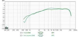
Checking a whole bunch of tweeters. Here is a comparison of (1) a ceramic tweeter with a fancy horn that bought for can$3, maybe 50 years ago and (2) a Fostex planar (may have been in a top-end Infinity) with model number E110, looks similar to some at Madisound for us$700.

FR and distortion. Green trace is ceramic, not that you can tell the difference in traces.

Impulse plots look similar too.... believe it or not. But ESL trace better.

Glad if anybody could tell me what is that Foster tweeter. Pictures will be posted later.

B.

Attachments

  • Tweeter FR.jpg
    Tweeter FR.jpg
    85.6 KB · Views: 403
  • Tweeter distortion.jpg
    Tweeter distortion.jpg
    76.5 KB · Views: 408
Projects by fanatics, for fanatics
Get answers and advice for everyone wanting to learn the art of audio.
Join the Community
507,921
Members
7,893,748
Messages

Filter

Forum Statistics

Threads
406,494
Messages
7,893,748
Members
507,921
Latest member
bedomes