Small Speakers flat from 50hz to 20,000 khz, is it possible?

Newbie here, with some primitive questions.

Do not know too much on SPL, crossovers do not have any tools to measure stuff nor know how. Would need to pay someone most likely to design something and guide me thru the process.

Scenario, a pair of computer speakers (no 2.1), listening range is only 2-3 feet, do not care how they sound past 3 feet. Closed cabinet and stuffed, do not like ported speakers.

Two 3” drivers and a tweeter, could be 2.5 or 3-way, could be passive bi / tri-amped, or active bi/tri-amped not sure yet, open to all scenarios.

Most 3” drivers in the 84 - 88db SPL range roll-off around 120 – 100hz and at 50hz they are around 72db – 73db. That’s if the specs are not inflated. Was told that the specs at 1 meter are based on low voltage and do not translate to real life…not sure what it means.

If I want it to be flat from 50hz to 2000khz or 4000khz at around 80 db then cross with a tweeter, what is the solution without adding any gain via tone control to that 50hz-120hz range or any color to the sound?

Running two 3” in parallel would add 6db so I’m already at my 79db - 80db from 50hz to 120hz, but after that if I want to run only one 3” as mid range up to the tweeter.

What type of filter or EQ or solution is needed to run one 3” from 50 to 100hz at it’s full SPL, then cut it off either 6 or 12 db slope, then past that 100hz mark somehow the second driver drops by either 4 or 8db depending on the tweeter I choose not sure on the slope to avoid too much mud in the middle.

Can this be solved without DSP? And how efficient will it be without any peaks or too much mud in the low mid to mid section?

I can pick tweeter with low FS to match the slope of my 100hz so if its first order at 100hz I can probably push the mid range to 4000khz cross over.

In general if it’s off by 1,2,3, 4 dbs…. how much can an average human hear these 1-3 db peaks and valleys at such a close range of 1-2 feet, so if this problem is not solvable without adding gain or adding too much color with too much EQ adn have to live with minimal peaks and valleys?


Cheers.

Batting versus Acousta-Stuff

To refurbish some old transmission line speakers, I removed all the damping and installed bracing. I am now finding it difficult to replace the damping material as the line width is only about 3 inches by 13.5 inches. I don't have room to reach my arm in and evenly distribute the stuff. One speaker now shows about 3-5dB less output below about 50Hz. I am thinking I could more easily snake some 1 inch batting thru the line. My thought is to center the one inch material in the 3 inch dimension across the 13.5 inch width. I would put loose Acousta-Stuff behind the woofer (10") and then use about 3 feet of batting. That would leave the last 2 feet of the 6 foot line empty. This would compute to the same 0.5 lbs/cubic foot density as the original. I am Biamping with line level 150Hz crossovers and applying eq. Any thoughts on how this might work?

Satori wo24p-4 subwoofer/woofer stands

I posted about this awhile back but didn't really get anywhere. I am ready to put some money down and something built before my next kid comes (likely the end of my DIY opportunities).

I need to build a subwoofer that can play from 200hz to 20hz (150hz to 30hz is fine too). I need it double as speaker stands due to space limitations. My plan was to build something that could be used to turn a bookshelf (LS50M/Sierra LX) into a pseudo 3 way if needed, or use low order crossovers. I was planning on using a minidsp 2x4hd and crown xls 1502 for the woofer/sub. I have a hypex 252nc for the mains.

I was aiming for something 24-26" tall, and 10-12" wide. Approximately 50L or 1.75 cu ft plus or minus 20% or so. The plan was ported with the ability to seal the port. So I am targeting a QTC 0.707 for the sealed volume. I was looking at using Jeff Bagby's Woofer modules active but when I looked at the CSS SDX10, the official parameters are all over the place (likely from newer iterations or changes in manufacturing? . The audioexcite review also showed what I thought were inconsistent parameters to model with. So really I'm not sure where to go with this.

I am open to side mounting a12" driver but worried it can't play high enough and blend with the mains. I am also open to front mounted dual 8s, triple 6s, or single 10 inch drivers.

I was considering single:
SB satori wo24p4
CSS sdx10
Dayton RSS265 or bigger (not sure HO, HE, HF)

With the wo24-p, winISD shows with 25hz tuning a 3" port, 15inches long it gets me 15.5m/s air velocity at 20hz (-10db) with a 10v signal.

Does this look ok? or am I doing something wrong?

Since I am going active, with a minidsp and xls1502, should I just go sealed and correct it with dsp?

Thanks
Other suggestions are welcome!

OB Single Driver Eq

The idea comes from Papa's Equalizer presented by Dana on BA2021, talking about next Speaker Camp event. Nelson made a small Eq in order to give a bump on lower freqs, something similar as seen to ACN/B5.

PASSeq.jpg

So, as it could be very helpful for large OB speakers with single driver (only the fullrange), why not combine that cell with a variable notch like on B5? It will probably be amazing with big fullranges like AN or Lii (especially 15 and 18"). What do you think?
Cheers,
Vinz :cheers:

LifeO4 pure power supply MkII with battery holder + ES9028Q2M DAC HAT

LifeO4 pure power supply MkII withsoldered battery holders

Since I collected a lot of parts in the past for projects I planned but for different reasons
never started. I now have to clean up a little bit.

I have a IAN Canada LifeO4 pure power supply MkII Board with soldered Battery holders, only used some hours for testing.


140,00€, shipping included within EU, for other countries please ask for shipping costs. SOLD!!!

+ an unopened IAN Canada 9028Q2M DAC HAT for 35,00€, shipping included


20220508_192412.jpg
20220508_193057.jpg

busted the potentiometer on my Thorens TD203

hello. yesterday while trying to adjust the speed on my Thorens TD203 turntable I busted the 33 1/3 RPM potentiometer, now no matter how much I rotate it, nothing happens. I looked it up, apparently this happens a lot as the thing is very tender and the instruction manual makes this task look rather simple. after the 33 1/3 RPM debacle I unscrewed the controller housing and adjusted the 45 RPM potentiometer live, applying caution - this worked like a charm. so, the question is - can the 33 1/3 RPM potentiometer be replaced? also, could I perhaps get away with an affordable variable (bench) PSU? if I understand correctly, I need to adjust DC voltage the motor receives.

Photo 08.05.22, 14 59 15.jpg

Photo 08.05.22, 14 59 18.jpg

Photo 08.05.22, 14 59 32.jpg

whazza "Hyper Bass Reflex" ?

[ DIY ] Hyper Bass-Reflex Type Enclousures (for Single Driver) - DIY - Loudspeaker | Low-end Speaker Craft

tough to wrap pea-brain around this thing and how it might vary as the maker
works with little fullrange drivers - in the try below, it looks like a MLTL

Rough stab at a "hyper bass reflex" roughly using the "rules" below for the low qts B&C 12pe32 vs similar bulk reflex

rwmoi5f.jpg


Hyper Bass Calculations

hyper-04.jpg

Splitting Line Level for Subwoofer output?

Hi,

There is an older thread on this but not much detail.

I see some 2 channel preamp builds where the line input is tied in parallel to the subwoofer line level output.

The integrated amp I’m using does not have subwoofer output. The subwoofer does not have high level input.

So what if I just use Y-splitter on the line level going into the amp and then to the sub. If L and R are split but then combined to one signal to the subwoofer input, does that
not just combine the L and R going into the 2 channel amp?

I know the current trend, some use the minidsp but that just brings up the cost.

Opamp better than OPA2604 with big soundstage, and analog like sound?

Good morning. I'm looking for opamp better than OPA2604 witch big soundstage, and "analog" like sound?

But e. g. opa627 (in dual), lt1028 (in dual), lm6172 is too much speed, and are unstable in my tube-opamp hybrid preamplifier.

Anybody know beter opamp than OPA2604 with realistic "analog" like sound and good soundstage? (Without discrete opamp).

Thanks

High frequency roll-off

Hello everyone!

I have been doing some bandwidth measurements on a SE prototype amp, and I can see a decrease of the output voltage at higher frequencies, reaching -2.5dB at 20Khz (pure resistive load):
sweep_7vRMS_output.png
I have checked the levels at g1 of the output tubes, varies very little:
1Khz: 106Vpp
20Khz: 103Vpp
The only think left is the output transformer, which is from Aliexpress. Should I assume most of the high frequency roll-off is happening due to the output transformer? The amp is not using global negative feedback, below the schematic for reference.
SE_2x6P41S_6N1P_InputStage_v2.png
Link to the output transformer: https://www.aliexpress.com/item/4000899015634.html?spm=a2g0o.order_list.0.0.367c18020HinhR

Thank you!

Hafler 9130/Pro1200 circuit differences?

A question for fellow Hafler owners.

I'm modifying my Hafler 9130 amplifier, and have been comparing the schematics between it and the Pro1200. They both appear to be identical except (except for one resistor, R21) and the separate circuit that looks like the power supply to drive the front end.

I'm no expert on circuit design, can anyone suggest the difference between these two circuits, I assume the 9130 version is simply a "better" design and the Pro1200 version simplified to lower costs?

-Bryan

see attached

Attachments

  • comparison.gif
    comparison.gif
    70.5 KB · Views: 290

Your thoughts on a custom power transformer...

Hello everyone! I hope you can offer some advice?

I purchased a custom power amplifier from an older gentleman who designed a Class A stereo power amplifier based on the 304TL transmitter tube. The primary winding of the custom Hammond transformer shorted after several years. I spoke to the designer of the amp and he made some modifications for an updated transformer to replace the tranny that shorted with some better specs that can be dropped into place replacing the defective one (diagram attached).

I live in Canada and Hammond doesn't do one off's any more. I called another company called Electronics Craftsman in Ontario and same issue where they don't do one offs and require a minimum of 6 (Hammond requires a minimum of 10). I contacted Edcor in California and they said they cannot help. I know that maybe supplies are difficult to come by and many smaller companies might have gone out of business due to the pandemic? If anyone has any suggestions for me I would surely appreciate your thoughts and advice? The amp is only several years old and the older gentleman created something quite special here. More importantly the sound is wonderful and I have some great synergy happening within my system.

As a last resort, I may have to break down this transformer into smaller transformers and create a separate power supply unit and connect the two units through a cable.

I can't send it back to him for servicing as it was crated and shipped to me and we are several thousand miles apart. He lives in Calgary, Alberta on the West Coast and I live in Nova Scotia on the East Coast.

I have attached some files that will be of some use to you. This is a big transformer! The amp is beautifully crafted.

Attachments

Cary SLA-70B biasing issue

Hi All,
I recently acquired this Cary Audio SLA-70B and am really surprised at how good it sounds. I've had a couple of other Cary amps, and this one is the best of them. Anyway, the previous owner had broken a tube, and replaced it with a mismatch. I just plopped in a quad of cheaper chinese el34's to make sure it is up and running in good health. I went to bias the tubes, and discovered that the procedure outlined in the Cary literature doesn't work. The tube fuse has been completely bypassed somehow--you can remove the fuse, and the amp still runs fine. Upon internal inspection, it is obvious why--the fuse socket is disconnected. So that leaves me trying to figure out how to bias it. I have circled what I believe is the biasing pot in blue on the picture. I attempted to measure the current below the resistor that sits between the pot and where it is grounded on the capacitor, but could not get any current to register with the amp on and warm. Any guidance would be appreciated. I would also be interested in rewiring the tube fuse back into the circuit. --Jaybird
bias questions.jpg

Pairs of BG NEO10 and NEO3 for sale

Selling a pair of NEO10 and NEO3. I have used them in my previous open baffle setup hanged in main baffles:
1594396391990.jpg - Google Drive
NEO10's are sandwiched in their own baffles made from cork and covered with felt. In this setup they were flat from 600hz and needed no equalizing at all. I used 3khz crossover between NEO10 and NEO3.
NEO3's also have some felt on their edges (treatment for baffle edge diffraction) and hair rubbers for hanging them in main baffles.

Front and back pictures of both pairs:
neos-front.jpg - Google Drive
neos-back.jpg - Google Drive

I will send them as they are - with baffles and felt.

Price for pair of NEO10s - 450eur, NEO3s - 150eur for pair + shipping from Latvia.

Thoughts on "tracking tangentially to the groove"

Hi every one,

It is popular on the DIY Audio Website to use the phrase “tracking tangentially to the groove”, relative to discussions concerning tone arms.

I spent Monday afternoon downloading a Microscopic view of the groove in an LP and then tracing over the middle groove with a spline and turning that into a PDF drawing to illustrate the gross inaccuracy of the above phrase.

I used the same groove three times to show three successive positions of the stylus as the LP rotates.

The first position of the stylus shows it to be tangent to the groove at an angle of 11.82º CW relative to the vertical.

The second position of the stylus shows it to be tangent to the groove at an angle of zeroº relative to the vertical.

The third position of the stylus shows it to be tangent to the groove at an angle of 16.8º CCW relative to the vertical.

Assuming that the tone arm mounting hole is located vertically above the second position of the stylus, it would have to relocate itself 2.327” to the right of stylus position #1 to remain “tangent to the groove” and it would have to relocate itself 2.327 to the left of stylus position #3, to remain “tangent to the groove”. My hat would be off to the tone arm designer who could design a tone arm capable of accomplishing that.

Illustration No.1 shows a record groove at a scale of 927:1. I picked the middle one because it was suited best to make my point.

Illustration No.2 shows the same groove three times with the stylus in three successively different positions as the LP rotates. Tone arm pivot to stylus distance is: 9.200”.

(I don’t dare mention variable groove pitch which would make matters worse)

Sincerely,

Ralf

Attachments

name a good lamination glue for whole sheets

I'd like to bond two sheets of 3/4" all wood plywood. For 1.50" low inertia sub boxes. I use white LePages contracter glue for just about everything else. Is there something made more for this purpose? A bottle costs $15 and doesn't go far when I laminate with it.

What about construction adhesive applied with a half inch notch trowel? I thought I remember a guy using a two part adhesive. What do the pros use?

I don't want the thing letting go and vibrating when the sub is in operation. Which did happen before lol.

Two questions taming sharp treble on a set of Magnepan 2.7QRS & anyone ever used PA power amps with their maggies

I know the pa gear sonds like a dumb idea but the 2.7s are huge (over 6 ft) and im looking at budget ways to get some serious power to them. Im currently running a set of Monarchy Audio class a amps which are ok but obviously the big maggies would eat up some more power and put it to good use? is a pa amp an idea? i have balanced xlr outputs from my Nad dac so that side of it is covered and the other thing as mentioned above how do you tame sharp trebble in maggies in a medium room when you have a wife that forbids acoustic treatment?

Marti CLA40-H Modification Help ( First Mod Project )

Hey all, I recently bought a Marti Electronics CLA-40H and I'm going about making some aesthetic changes. I'm going to relocate a bunch of switches as well as get a new aluminum faceplate. This is my first big project! Any help at all would be amazing. The first three pictures below is the way it looks now and the last picture is the type of mod I'm aiming to achieve.

Marti CLA40-H Manual

Switch Type Changes & Relocation
There are two switches on the back that I'd like to change from slide switches to Potentiometers and move to the front. Any advice or help finding them would be much appreciated.
1. The first one Is a Stackpole DPDT Switch ( 3a 125vac, 1.5a 250vac, .5a 125vdc ).
2. The second one is a DPDT Switch from switchcraft ( 3a 125vac, .5a 125vdc )

On/Off Switch
There doesn't appear to be an On/Off Switch. Where in the circuit would I add that? And how!? Like the one below

On/Off Light
Like the picture below I'd like to add an On/Off Light. Where in the circuit would I add that? And how!?

Thank you for any help you can provide


1651980446296.png
1651980514211.png
1651980658123.png
1651981567031.png

what driver to use for Tham15 x4 from a single 20A outlet?

Im toying with the idea of trying to buy drivers for (4) Tham15 cabs, that will run off a single 120v 20A circuit.

Kappalite 3015LF neo (expensive)
Dayton PA380 (does this work?)

Any suggestions that keep them sounding good, dont break the bank, and meet the proposed power situation? Or is it just a bad idea?

Or should I buy the recomended drivers and run the amplifiers at half power?

Tannoy MG15 distortion problem

Hi, i just aquired a pair of vintage Tannoy monitor gold 15" from an uncle and i need some advices on a problem.

They were sounding good for a month until one driver started to devellop some kind of low mid distortion with bass notes and it also lost some bass it seems. The high frequencies sound very nice and don't seem to have any problem.

I narrowed it down to the driver, i also redid the crossover and contacts to verify it wasn't the problem but it hasn't cured it. ( i even changed the connectors and bypassed the crossover switches).


When i apply a small pressure with my finger at some spots on the dust cap or some spots on the cone, the distortion goes away and the bass come back sounding clear and very good.

Which makes me think it's a mechanical problem at this point and i'm pretty bummed..

The speakers have low usage and probably never were abused and I cannot see any visual signs of damage. (these are not the version with the foam surrounds).


Anybody has seen these kind of problems with Tannoys dual concentrics before? What are the possible causes? any fix?


I'm kinda out of ideas but my next step might be to try to rotate the speaker 180 degree in case it is related to the "spider sagging" as i have read here.


I realy hope i can revive these .. 🙁

Thanks.
John

Sunfire True Mk4 common issues & fixes?

Hello, im looking for a list of common issues and bad parts of this model.
i bought one and it takes a while for coming out of standby, i have to turn the gain knob all the way up and some minor humming is audible


from what i can find on the web there are only repair services that charge 200+ bucks for probably just replacing caps.


does anyone know of common parts that go bad or were of poor quality?
replacing all caps is #1 on my list.


i wonder how they manage to make it safe to use, the internal parts are not even galvanically isolated from the mains.
apparently it has a isolation transformer. ive seen some pics of them without. must be eu model or something.

Sunfire True Subwoofer MKII -- Light comes on, but no sound ==

AMP looks good, but does not make sound.
When I first plugged it in it made sound, but sounded very distorted; barely corresponding to the input signal
Then it only made a slight hum
And now it does not make any sound, except when I unplugged it it pops a little

It looks good, where to begin testing or repairing it?
I'm not good at repairing these things, but sometimes I get lucky and it is usually because some one had the same problem and fixed it and told me how to do it

I recently tried to fix a Velodyne micorvee subwoofer and gave up after changing a lot of the caps I think I only had two "chips" to replace, but just gave up. I think I messed up the board a little trying to fix it

Attachments

  • IMG_20180320_133316.jpg
    IMG_20180320_133316.jpg
    1 MB · Views: 595
  • IMG_20180320_133346.jpg
    IMG_20180320_133346.jpg
    1 MB · Views: 446
  • IMG_20180320_133353.jpg
    IMG_20180320_133353.jpg
    1 MB · Views: 400
  • IMG_20180320_133407.jpg
    IMG_20180320_133407.jpg
    1,001 KB · Views: 334
  • IMG_20180320_133546.jpg
    IMG_20180320_133546.jpg
    1,003.8 KB · Views: 474

Best way to make a hot-swap connection for capacitors?

Hey


I am looking to do some A/B testing with and without bypass capacitors to see if there are any meaningful changes in sound.

Is there any way I can do such a thing without having to solder and desorder?

Ideally, it would need to be as fast and hassle-free as possible because our auditory memory can only last so long. However, a high-quality connection is preferred to eliminate as much additional inductance or audible sonic degradation as possible.

Do you guys have some suggestions? I came across a forum post where someone did that, and he used copper alligator clips. https://www.distrelec.ch/de/krokodi...t5mrV2aO7a65SHZX9IJdRkZbe5zmM0-xoCWE4QAvD_BwE

I also considered these: https://www.ebay.com/itm/333324685360 and soldering the PCB mount part to the capacitors that I intended to bypass, but I think it would take longer to swap back and forth with this variant.

Any suggestions are welcome!

Speaker, Speaker Cable & Amp Matching

Evening All,

decided to post here as I've an F5 and ACA, both perform their best with 4 ~ 8 ohm loads.

for argument sake, lets assume I'm using either amp and my speakers are 8 ohm.

in the perfect world, if I could tap the amp post's directly onto the speaker post's, meaning I don't use speaker cables, then cable losses are eliminated. However as soon I use speaker cables the system is no longer a perfect amp speaker match correct, particularly if my cables are high impedance, say up around 60 ohm ?!?

If however, the speaker cable was a perfect 1 ohm impedance, am I correct in saying losses would be at their minimum and I'm effectively nearly in the same boat as not using cables at all? In other words, 1 ohm cable and 8 ohm speakers would see 9 ohm load at the amp?

For this scenario, lets assume the speaker cable capacitance and inductance are average values for speaker cables

Thanks AL

JX500/1D driver IC

I have a broken JL JX500/1D with a busted power supply. I have only taken time to identify the issue, I assume this is the driver IC for the FETS, they don't cross to any thing either. I can't cross this device M18021HN. There is a missing section of the IC that starts MPS. There a 4 power supply transistors, two are burned. Any Ideas? I have added attachment with picture.

Attachments

  • jl amp.jpg
    jl amp.jpg
    390.2 KB · Views: 444

Nakamichi AV-10 source switching fault

I'm trying to repair an AV-10 with a curious fault, which I have seen other people with similar symptoms but no sign of a solution yet. Curious to know if anyone here has any thoughts :
  • When powered up, the standby light comes on, but the front power button doesn't do anything. The rear power switch operates correctly (ie turns standby mode on/off)
  • Pressing the Memory button turns the unit on/out of standby(consistently)
  • Pressing the Tuning Mode button turns the unit off/into standby (consistently)
  • Pressing other buttons has no impact (power, tuning, input selection, etc)
  • When powered up, out of standby mode, the front indicator LED for Video 1 is lit
  • Feeding an audio signal into the VCR1, VCR2 or Tape RCA Outputs will result in audio output being sent to the speakers, with adjustment possible via the volume control.
  • Feeding an audio signal into the F/R pre-out RCA will result in full volume output at the speakers (not sure if that would always be the case)
  • The A/B speaker switching, loudness and tone control circuits are all functioning (scratchy tone switch, which I will fix)
  • Disconnecting boards other than main board and front PCB has no impact
I have confirmed operation of all micro switches and measured all the resistors in the ladder network feeding into the main IC001 controller and they all look ok. It doesn't make sense that the Memory/Tuning switches each generate a voltage/current that mimics what the Power switch should do, so perhaps there is something wrong with IC001. If that's the case then I guess there would not be much I could do, even if I was skilled enough to remove and resolder that component, they are hard to find and I'd have to program it somehow.

However, I've been tracing through the circuits and reading someone's repair notes made on an AV-8 with a faulty audio switch IC, and given that feeding a signal into the RCA outputs results in output at the speaker terminals, I'm guessing there must be a problem with the audio switch ICs so I was planning to replace those as a start. I've not been able to find any signs of broken/cracked tracks and have tried putting pressure on the boards in different locations and there's no impact. I've found a few resistors and transistors in the power section that have signs of high temp on the board, but they all test ok. I don't have a scope so can't look at the control bus.

Afternoon Delight

I noticed "Afternoon Delight" on the "One Hit Wonders" thread on another board earlier this week. It was a No. 1 hit in 1976.
They never had anything in even the top fifty again.

I hadn't heard it in decades but I've always liked the harmonies.

I noticed a copy on eBay for £3.99 with free postage, so I said, "hang the expense" and bought it.
I'd bought another single a month or so ago, but hadn't yet put it in one of my jukeboxes.

So I've been on one of my jukebox enthusiast's website and downloaded the title cards in PDF form to cut out and use. This is a free service, I hate seeing jukeboxes with hand-written title cards.

You go on the site, type 'em up in styles, colours and fonts of your choice and print them off.


[IMG]


I bought the Rainbow one on eBay a few weeks ago for about the same money.

Forty-two years ago, we had a birthday party for my wife's 40th birthday.

There were a few of my friends there from my squash club, but mostly hers, who were of similar ages. I'd made up a few cassette tapes of contemporary popular music that would appeal mostly to her friends, but included these two. There was a bit of a shocked reaction from some of her friends, unfamiliar with heavy metal. It always makes me smile when I think about it. I've not yet put it in.

Anyway, the new record arrived today. Unlike iPods, if you want to put a different record in a vinyl jukebox, you have to choose one to take out. In this case Stevie Wonder has joined many others in my "retro" record rack.

There you go.


Login to view embedded media

Advice on Visaton configuration

Hello all,

I am trying to upgrade my set of loudpseakers, and would need a little help on the crossover design.
The system is a 2-way, with Visaton W170S/8 as woofer, and I've chosen SC10/8 as tweeter (also from Visaton).
The total volume of the box is around 42 liters, it's tuned to some 33Hz by the means of a bass reflex port. The baffle size is 79x23.5cm, with 1cm chamfers on all 4 sides.
The crossover point is around 2500Hz.
My problem is that I do not manage to get the off-axis freq response right (without significant dips or peaks).

I know that the woofer/tweeter combination is not the greatest in the world, but I think that there is a possibility to make things better.
Can some of you give me some advice on how the situation could be improved (I am talking about the ~3dB dip at around 1700Hz)?
If I remove the 0.82mH coil from the treble, the horizontal FR seem to improve, but then there will be a huge dip of 8dB on the vertical off-axis FR.

I have attached the Boxsim project, and some frequency response graphs.

Attachments

  • boxsim_capture.png
    boxsim_capture.png
    165.5 KB · Views: 519
  • W170S_SC10N_forum.zip
    W170S_SC10N_forum.zip
    24.4 KB · Views: 96
  • crossover.png
    crossover.png
    7.4 KB · Views: 522

Yamaha B-2

Been hunting for one for some time, but wasn't going to spend 2k, ormore and then have to go through it all on top of it. I found one that has a few dings and made an offer for 1k. The guy took it, so sometime if the next month I will have this wonderful old girl on the lab.

Let's hope I didn't get hosed. :rofl: 
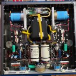
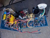
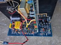
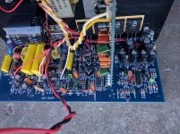
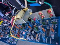
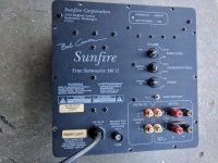
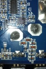
Hell as long as the FETs are good, I can't lose anyway. It was said that it is working fine, we shall see.

JT

ESS3038Q2M from Ebay

I bought tis dac from ebay thinking I could do sommething with it and a couple of regulators.
Am I right when I say that there are 3 regulators neede?
https://www.ebay.com/itm/1145514035...var=414734175880&_trksid=p2060353.m2749.l2649https://www.mouser.se/datasheet/2/1082/ES9038Q2M_Datasheet_v1_3-1923484.pdf
VCCA pin 12 3,3v
VCCA pin 27 3,3v
DVCC pin 13 3,3v
And pin 15 is Digital core voltage nomilaly +1,2v supplied by an internal regulator from DVCC.

And I´m going to use my Tube I/V.

Tweeter aging louder or softer?

I have a pair of Wharfedale speakers, they are only a few years old. Say at a certain volume setting, one tweeter would be 90db at 0m, and the other would be at 87-88db. The measurement technique is far from scientific, but it reflects what I hear. One side is louder than the other and center image is skewed. But other than the volume, I could not detect any distortion or anything wrong with the sound.

I did some troubleshooting and concluded the issue lies with the tweeter and not the crossover or the electronics.

So I assumed the softer tweeter is faulty. My working theory is it uses ferro fluid which dried out. Just a guess, I have no idea what really happens.

So I ordered a replacement tweeter. When it came, it is 2-3 dB softer than the softer tweeter. If compared to the louder one it is 5-6dB difference.

FWIW original tweeter pair has stickers that says "2018 19". The replacement's sticker says "2013 19". Assuming they meant the year of manufacture, it supports the ferro fluid theory. And the replacement tweeter is even worse than my original pair.

But before I jump to conclusion, is there any scenario where the good tweeter is in fact the least sensitive replacement tweeter? And as they age and degrade they somehow become louder?

soundqubed s1-1250

Hello everyone! I bought this amp already broken and it had a red protect light on. Measured and found 1/8 power supply fet (irf3205) shorten and 2/10 output fet (irf640n) also shorten. Took of those broken parts off the board and powered the amp up. Seems like it works properly without these burned fets. So the question is: can I use the amplifier? As I don't have enough these fets I need to order them but could I connect it with a subwoofer (1ohm)?
I would have 8pcs of irf640 (without the N suffix) but unfortunately only 8 not 10 what would be needed.
Thank you for any help.

Woofer/sub module

I posted about this awhile back but didn't really get anywhere. I am ready to put some money down and something built before my next kid comes (likely the end of my DIY opportunities).

I need to build a subwoofer that can play from 200hz to 20hz (150hz to 30hz is fine too). I need it double as speaker stands due to space limitations. My plan was to build something that could be used to turn a bookshelf (LS50M/Sierra LX) into a pseudo 3 way if needed, or use low order crossovers. I was planning on using a minidsp 2x4hd and crown xls 1502 for the woofer/sub. I have a hypex 252nc for the mains.

I was aiming for something 24-26" tall, and 10-12" wide. Approximately 50L or 1.75 cu ft plus or minus 20% or so. The plan was ported with the ability to seal the port. So I am targeting a QTC 0.707 for the sealed volume. I was looking at using Jeff Bagby's Woofer modules active but when I looked at the CSS SDX10, the official parameters are all over the place (likely from newer iterations or changes in manufacturing? . The audioexcite review also showed what I thought were inconsistent parameters to model with. So really I'm not sure where to go with this.

I am open to side mounting a12" driver but worried it can't play high enough and blend with the mains. I am also open to front mounted dual 8s, triple 6s, or single 10 inch drivers.

I was considering single:
SB satori wo24p4
CSS sdx10
Dayton RSS265 or bigger (not sure HO, HE, HF)

Other suggestions are welcome!

Phono preamp hum

I have a friend with hum problems in his phono preamp, attached schematics.

If someone can help me to simulate with LTSpice to know wich values of voltage are correct to measure will be very helpfull.

TIA

Attachments

  • HV reg phono Jordi diyaudio.jpg
    HV reg phono Jordi diyaudio.jpg
    167.6 KB · Views: 419
  • PREVI PHONO JORDI DIYAUDIO.jpeg
    PREVI PHONO JORDI DIYAUDIO.jpeg
    100.9 KB · Views: 453
  • WhatsApp Image 2022-04-27 at 11.22.40 PM.jpeg
    WhatsApp Image 2022-04-27 at 11.22.40 PM.jpeg
    255.5 KB · Views: 393

6SL7 or 6SL7GT for broken Tubalizer

6sl7 or 6sl7GT for Broken Tubalizer

Hi everyone,
I have just received an Audiodigit tubalizer that unfortunately isn't very healthy. :dead:

http://www.audiodigit.com/?section=81
This is my first experience of valves and hopefully will lead to more adventurous things.

THe Tubalizer is placed between my CD Player and Integrated (14KOhm input impedance) solid state amplifier.

It distorts very badly with any input. It is slightly better with very small signals (-12dB) but not at all satisfactory. I have tried many sources and different power supplies and 'tuning' settings.

I am using a 12v 1.2Amp regulated linear supply with the correct polarity. I have also tried other supplies with no change. My power supply gives 12.06 Volts (unloaded) and the regulator is passing approximately 6 Volts and the tube glows slightly near the top as it should.
I have redone all the soldering to be sure and measured 5.7Volts at the ground of the RCA outputs (This is as it should be.)
This device is only made from a handful of caps and resistors with a 6 Volt regulator and a Sovtek 6SL7.

Surely it must be a faulty Tube? What else could be wrong here? Any help would be very much appreciated. I would eventually like it to be my CD players output device when I get it working.

I feel I should buy a spare valve for test purposes but what is the difference between a 6sl7 and a 6sl7GT?
Please help :bawling:

Python Software AWG for SDS1404X-E

A Sunday evening project.

The python AWG project allows a PC to work as an intermediary for the non Siglent AWG for producing Bode plots: GitHub - 4x1md/sds1004x_bode: Bode plot with Siglent SDS1004X-E oscilloscopes and a non-siglent AWG.

Now there's a couple of other options - including AS9850 etc but the most simple example would be to have python create a wave file and play it.

So I'm making a software 'driver' for the git hub software that simply acts as if it was a AWG using the headphone output as the audio output.

Code:
import numpy as np
import simpleaudio as sa

frequency = 440  # Our played note will be 440 Hz
fs = 44100  # 44100 samples per second
seconds = 3  # Note duration of 3 seconds

# Generate array with seconds*sample_rate steps, ranging between 0 and seconds
t = np.linspace(0, seconds, seconds * fs, False)

# Generate a 440 Hz sine wave
note = np.sin(frequency * t * 2 * np.pi)

# Ensure that highest value is in 16-bit range
audio = note * (2**15 - 1) / np.max(np.abs(note))
# Convert to 16-bit data
audio = audio.astype(np.int16)

# Start playback
play_obj = sa.play_buffer(audio, 1, 2, fs)

# Wait for playback to finish before exiting
play_obj.wait_done()

The above is the basic structure as an example from the web. It shouldn't be too difficult to change the AWG to use this. Naturally this has all the mac mini filters in the way.. but the same could be done using a PI etc.

After much gnashing of teeth - I managed to get the Ubuntu VM inside VirtualBox running on my Mac mini connected by ethernet to allow the connection from the SDS1104-E. The bode plot is random output as I've not actually got the probes connected to anything!

Screenshot 2021-11-07 at 16.17.44.png

KEF R700 problems and testing ideas

Hey Everyone. It's been a while 🙂

I have a pair of uni-q drivers who's midrange units seem a note apart. One is too high pitched, forward and lacks air. The other has an almost dark quality I find very appealing. I have heard dark as a description in reviews, and it sounds very good. The other... well quite cheap really. I can only weigh up the sound between them as I got them used, and have heard no others.
After every component on the crossover was swapped out. Cabling. Electronics. I pulled the units out and put them on the table with just a capacitor on a speaker wire I moved between them. Sure enough, about a note apart regardless of sine wave frequency fed to them, or white noise.. voices.. So I swapped them over to be sure it wasn't my table. Put stickers on and did the switcheroo so I could blind test. There is no small difference between them. It's a note. My phone registers this higher frequency unit a couple of db higher.

Sounds like little else to look at? So I sent both off to Kef to be sure of which one they thought sounded right, before I bought another. My first reply was they work. I think it was a 9v battery test. They then had more serious testing done and some artifact in the lower regions showed that was unlikely to ever be heard.

I'm now stumped. They seem to think I should buy more, but that these are fine. Is there anybody that can test these properly in the UK, that perhaps has such a uni-q themselves to give an authoritative view? I'm going to get them back and suspect an issue in the voicecoil area. I understand from the pics there is a chamber of damping material so perhaps it's in contact, or the coil just needs a little shellac. Might a gain in higher frequency noise come from such things?

I'm a bit lost. I got the kefs as my 50th present. eBay so typically broken. 3 months in, I'm yet to enjoy them. I think I need a second opinion.

Restoring a subwoofer power amp

All,

I'm in the process of restoring a 20+ years old subwoofer which was sold to me for a few bucks as 'doesn't work, sound is very low'.
After testing the two speakers, the power supply and measuring the amplifier board components, I came to the conclusion that power supply caps are leaking / to be replaced and that one differential input stage transistor is fried.
See input stage schema below which I simulated with ZTX851 and ZTX951. It was initially built with 2SC2389 and 2SA1038. I have one 2SC2389 fried, the rest is measuring ok.
I'm planning to replace the 2 2SC2389 at minimum and wondering if I should or not replace the 2 2SA1038 as well to have the 2 pairs from equivalent series.
Any advice would be welcome 🙂

Enjoy day !
Jean-Francois


1651924105724.png

Self contained electric acoustic u-bass

Not sure if this belongs in this forum or the instrument one, here goes.

I am building a self contained electric acoustic u-bass, basically I bought a u-bass from:

Kielder Bass ukulele by Buzzards Field Ukuleles

and I want to put the amp and speaker in the body of the bass, powered by a battery, for a mini self contained bass. Amp, driver and battery as follows:

TPA3116D2 Subwoofer Digital Power Amplifier 100W AMP Board Audio Module UK | eBay

Buying a SB Acoustics SB13PFC25-4 woofer? | SoundImports - SoundImports

Power Bank XT-16000Q3 with 24V Output from XTPower

So now I need to design an enclosure that fits inside the body of the bass, and gives me the necessary response. I would like to do a vented enclosure, but it may be too big. How do I go about calculating the volumes, port size, etc.? Will I be able to get good response down to FS of 44Hz in a sealed enclosure?

Any advice is appreciated.

Open baffle boom box?

I have been reading a lot about and slowly falling in love with the open baffle concept. I bought an Executive BT kit last year but with a new baby never found the time to put it together.

I was thinking about repurposing the batteries + amp + CX120-8s combined with 1 GW-215/4 in some kind of origami briefcase setup to listen to outside. I want to keep it light and compact so it would kind of fold in on itself for storage but then open up relatively wide for some soundstage. I would store it indoors so weather issues are no problem I think. Has anyone done anything like this?

One specific question I have is with the baffle thickness for the sub. Obviously a thicker baffle would be ideal but they are heavy. Could I get away with say 3/8" plywood with reinforcements? What material would have the best combo of low weight and strength? I guess another question is whether it would be worth getting more efficient full range drivers to get more battery life. Just curious what other people's experiences have been.

Does such preamplifier exist ?

Hi everybody,
thank you for showing attention to this thread 🙂
Does such preamplifier exist ?
I`m not guy who know a lot in electronics department and this why asking for help me out.
I would like to have preamp "signal" multiplayer ,if that description makes same seance...🤔
Situation is like this ...mono signal ( separate left and right channels) out of DAC ( Fostex HP-A4 , 2 Vrms) and in to preamp "signal" multiplayer where I can multiplayer to two identical signals out at the same value of 2 Vrms. Off course ,quality is priority. I should look like this:

Attachments

  • Preamp.jpg
    Preamp.jpg
    631.5 KB · Views: 136

McIntosh C20 preamp buzzing noise one channel

I bought mcintosh c20 preamp as is
Both channel sounds okay just little crackling noise when I turning the volume potentiometer
I cleaned the entire unit with contact cleaner and
I sprayed deoxit on each volumes and switches.
I dried three days.

Now, one channel is working perfect but
another channel has buzzing noise.

When I turn the main volume potentiometer to louder, the buzzing noise become louder.
Also crackling noise time to time.
When I turn the main volume potentiometer to very silent, I cannot hear the noise.

I switched inputs and nothing changed.

What could be the issue? is it potentiometer? or something else?
If it's not volume potentiometer, shouldn't be buzzing noise same level regardless of turning the volume?

port tuning - WinISD vs UniBox

I am comparing WinISD simulation for port tuning with UniBox.
If I use "theoretical" response the results are the same but if I use FRD file for Dayton DC300 in UniBox, the difference is huge.
I have made screenshots for port tunig in 138 l cabinet (4.87 cubic ft) with port diameter 7.50 cm. There is obvious that different
Fb should be used for the best results (the lowest F3). So which tuning should I use or consider to be better?
The "real" one with frd file seems more realistic but it´s a surprise that 12" woofer will get F3 only at about 33 Hz.
I do not have possibility to measure the speaker response in cabinet.

Theoretical response - port length 9,95 cm

response 1.gif


FRD simulation - port length 4,85 cm

response 2.gif

For Sale Seas 10” A26RE4 pair (Devore)

Seas 10” A26RE4 8ohm pair
I will sell at 30% of new price.
One woofer was gently tested for four hours. The other was packed up and looked at, and then put back in the box. Still has protective plastic knobs to protect the rubber surround, which would orherwise be deformed as it protrudes.
I ended up using the W26FX002.

Collection during May 2022 in both Oslo, Norway or Montreal, Canada, or sent anywhere.
Payment: Paypal is fine, also bank transfer.

F11A0742-E645-4F51-BFB4-E3DFB78DF542.jpeg

Bass Speaker Recoil

Hey guys, not sure where in the forum (if anywhere) I should post this.

Basically, bought a bass guitar amp dirt cheap because one day it worked, next day it quit they said. Had hoped a simple issue like a bad solder joint, but instead looks like the coil started to unravel inside and the wire eventually broke.

Managed to get the old coil out and the cone/spider are undamaged and still in place. Coil a bit deformed. I was able to get some measurements and about to make a paper mockup to ensure I have the correct diameter. Problem I'm having though is finding a match.

Seems like a 36mm or 36.5mm coil. 34mm tall. Where I am really having trouble is with the wire coil width itself. Everything online is between 12-14mm, and this thing is only 7mm.

So... first obvious question is, what would happen with a new coil if the winding width is 5-7mm too wide?

Does anyone know where a new one can be made without sending it in?

Should I attempt to make one? 32AWG wire isn't too pricey for a roll, though the roll is much larger than I need. Aluminum wise, I was thinking of a Coke can.

Thing is, it's a stock speaker from a Fender Rumble 75... it's generic made in China and not great to bein with. If I can fix it for $25, great... otherwise I'd rather just wait for a used 12" bass speaker to pop up for sale. That said, it's currently dead so, may as well learn and have fun with it. 😀

jl audio hd600/4 dc at output

hi everyone
comes to me a jl audio hd 600/4 playing only 3 channels. someone previosly test it and take apart the output mosfet on the bad channel.

if i install new mosfet the red/green protect lights on and dont work any channel. try with the good mosfets from another channel same thing.

irs2011 driver replaced. i have the same voltages in the bad channel like one working channel. if i play 60hz tone i see it on gates of bad channel and the signal is equal on another good channel.

i have 5 vdc on the bad channel all time. the amp has the same resistance from output to gnd on all channels. good output inductors. no bad traces.

if i install the mosfets the red/green protect lights on but if i take apart the 0.47uf blue cap the amps turns green and plays good 3 channels. the bad chanel has 5 vdc, plays but the speaker cone go all the way.

Anyone with a similar problem?

double checked caps, resistors and diodes on the irs2011 area
IMG_20220505_063432.jpg
IMG_20220505_063427.jpg

  • Locked
Vinyl is a nicely compressed version of pure Digital audio

Digital audio is the factual high fidelity and true musical king. Vinyl sounds like the sun faded old lady version. Somewhat nice but lacks the really strong, muscular and bouncy pepp in the step. Lacks the really high and the really low. Lacks the powerfully, juicy but still clean and pure total control.

But vinyl crackes really really nicely like stone age camp fire did more than 5000 years ago🤗🔥


Ok this sounds evil. But we know that is true. Or.

You got a very very tired stereo setup that really finds sonic benefits of the true vinyl compression and dirty camp fire crackeling. 😇

So, there, someone finally said it like it really is🤘🙂

Airflow as calibration for microphone frequency response?

I build a simple measurement-mic with a Panasonic WM-61A (or copy ?) from ebay.

It works, but I have no way of knowing whether it has a flat freq-response.

So, airflow/wind is white noise and if averaged over (long enough time) it should measure flat right?
Maybe a low-noise 12V fan and some ducting could provide a wind-source?

Sounds too simple, but whats the flaw?

Kind regards TroelsM

Amp boards with wireless sync in bluetooth stereo setup?

I'm sorry for the terrible title.

I build a PE Executive box and while I like the bass and overall response the narrow soundstage sucks. I want to repurpose and supplement its components to make 2 separate powered speakers that act as the L/R channels of a stereo signal. The simplest and cheapest thing to do would just be to make separate speakers and wire them from one amp.... but what's the fun in that? I know you can pair multiple BT speakers off the same signal so I am just looking for an amp board that would let me do the same with custom speakers.
  • Like
Reactions: rstutz

Suitable amp for compression drivers in PA

Wanna do some DIY. What’s a suitable amp board for a couple of 2” compression drivers with big horns? 16ohm 112dB of sensitivity, 200w max. 500-20khz. I mainly look for a low noise floor in combination with low THD and high SNR. I will probably run a max 1 watt through these so power isn’t the biggest challenge, but a headroom would be good I guess.

Any suggestion? Budget around $200 for board and Psu.

Nakamichi AV-8 no output to speakers H/P OK

Hello everyone,

Sorry long post!

I have been given a Nakamichi AV-8 receiver (saved from landfill)..

Good news is that it fires up (yay) and works through headphones (double yay) but there is not output to the speakers. There is no obvious component damage to the output stage. The display, switching logic and the output stage cooling fans fans are working. There's a clunk from one (or more) of the speaker protection relays when the unit is powered down and also if the A and B speakers are pushed on / off.

Bad new is that it's a nightmare to work on and I haven't managed to track down a service manual for it yet (although I do have a AV-10 service manual which I may be able to get by with). The output stage is arranged as a 'removable' rectangular box. There is no removable service panel beneath the main board which unfortunately I think is the location of my problems.

After an hour I had the entire unit stripped down (only way to get the main board out to inspect underneath) and observe a pair of DC rectified circuits which lead off to the protection circuit (and other things). There has been a fair amount of heat in this area (tell tale browning) and the dry joints beneath were glaringly obvious.

The challenge for me is that the entire device has to be fully reassembled again before it can be tested. After de/resoldering the area and reassembling the whole unit, good news id it's no worse, not so good is that it's no better.

I'm grateful for the AV-10 manual I have downloaded from Hi-Fi Engine but would feel more comfortable with a copy of the AV-8 manual if I can get hold of one.

Any suggestions appreciated (it's off the bench at the moment)

Ciao Blake

  • Locked
Ceramic cartridge to line level input circuit

Hi all,
As the title suggests I would like to connect a ceramic cartridge to a standard line level input on a modern solid state amp. I do not need RIAA equalization. On the thread https://www.diyaudio.com/community/threads/ceramic-pickup-preamp-schematic-needed.175822/ I found a circuit (attached) but I thought that I would touch base to see if this circuit is still valid. Also if anyone could tell me what that mystery component is.
Thanks

Attachments

  • t3.jpg
    t3.jpg
    708.1 KB · Views: 945

Seeking input: best/easiest textured coating for MDF cabs?

I have finally fully glued up three MDF subwoofer cabs of the DIYsoundgroup variety. I still need to flush-trim the overhangs and sand, but then it will be time to apply a finish. I think the best and easiest option for me would be a roll-on textured coat. I don't have any experience with using this kind of product, so I am seeking input. Also regarding the color. Some are black or white only, and some you can tint AFAIK. Is it worth getting a tintable variety so that I can choose the ultimate color and shade, or is that just making things more complicated and asking for trouble? What products and techniques do you recommend?

Near field subwoofer/subwoofers is the bass Nirvana?

Well. I have been thinkin… Near field sub bass?

First of all. Wiew this from the chill and cool old and true hifidude Paul:

Login to view embedded media

Well, now. I have built several high end car audio systems. Fully active DSP, multiple subs. And Thats Truely True Near Field 🙂👍

Here is my opinion on near field in home audio and subs: you do not want them, you do not need them, in all the lovely powerfullness they could and absolutely will bring:

If.

If you have got a stereo/surround system that is top notch matched, and have got large enough, fullrange and Powerful enough left and right speakers: Then. Near field subs is simply only the next best thing… To get that muscular, powerful, controlled, juicy bass. The true sub bass, and bass, We all really want and really needs😘


Dont ya think? 😎
What do you think, am totally wrong?

No, i am not wrong🙂


Edit: Enjoy🤗 The absolute king of the movie soundtracks. Hans Zimmer:

Login to view embedded media

Adjustable P/S up to around 50V

Hi guys, can anyone advice on a source (kitset OK) for an adjustable with a working out voltage of around 40 to 40 V, Prefer dual supply but can of course use 2 single's.

Bought this one from F/Bay, which was no good

https://www.ebay.com/itm/2534773923...+gy4VJXZfyk0LVeh5iBAfqyK7qs=|tkp:BFBMqsDW845g

As it will only adjust to 38V, supplier claims that manufacturer changed design & did not advice suppliers!!

Cheers

Tapped Horn Vs 6th order par.bandpass ?

I'm still looking for the "best" cabinet for my 12-280 8W woofer from Thomann (as described in this thread: https://www.diyaudio.com/community/...as-with-12-280-8-w.383285/page-2#post-6949739).

I sort of had dismissed tapped horns because of size, but a Tham12 comes in pretty close to my size-limit, so curiosity got the best of me and I started drawing/simulating a looot of TH-cabinets with actual internal volume up tp 75Liter. - some pretty efficient options in that range, BUT the boring downside is that I can make a HR-sim that gives almost exactly the same response for a 6th order parallel bandpass (within the same cabinet volume). I´m assuming that a TH would win if cabinet-size was not a constraint, but it is.

So, the question for this thread is: assuming that a 6th order parallel bandpass (HR: BP6P) and a TH are the same volume (60-80Liter in this case) AND have approx. the same FR and diaphragm displacement, which is better? Cooling must be better in a TH, but construction is also more complicated and heavier due to the internal path.
Looking at impulse responses for both systems, I cannot see which is better.
Use-case is indoor, small, party-setup. Lower knee (-3dB) can as high as 50Hz). must work up to 150Hz. Power around 200-300W

Kind regards TroelsM

I have a hole in my rubber ducky

I mean my PVC fishing dinghy. It's a pinhole. In the old days we just put on a 2" round patch. Sometimes it was self adhering like a bike patch but I think I like to use a patch with liquid for more secure chemical bonding. I am familiar with surface prep but I am wondering if there is a new and improved patching method or do I just buy a vinyl repair kit? I don't own a PVC welding gun.
Any help is welcome. TIA

Nakamichi MB 100 Audiocontrol Install

Good Day Gents!
I am a proud owner of a Mercedes Benz PRE MERGER AMG SEC Coupe. While maintaining the classic interior appointments, I decided to install the following components. A Nakamichi MB 100 with the separate DAC / Pre amplifier, Audiocontrol Epicenter, Audiocontrol 3.1 signal processor, Nakamichi DB 50 dual amplifier balancer, Nakamichi PA 304 4 channel amplifier for the front and rear satellite transducers, and a Nakamichi PA 302 2 channel amplifier ( bridged ) with a JL Audio 10 inch low frequency transducer. Here is where I would like to receive your input. The 24 Bit High Definition DAC Pre amplifier has an output selector with the option of using a 1 volt, 2 volt, and 5 volts, along with an Acoustic Response Compensator with Lower Midrange optional settings of 100, 120, 140, 160 Hz @ -10db, -5db, and 0 db.
The Upper Midrange settings are at 1.0k, 1.2k, 1.4K, and 1.6k with -5db, -2.5db, and 0db. It has dual front and rear outputs. To get the optimum output from the preamplifier, do you recommend that I incorporate Y Adaptors on the front and rear outputs into the input of the Audiocontrol Epicenter, and the output from the Epicenter to the input of the Audiocontrol 3.1 in which has front, rear, and sub outputs?
I am interested in receiving your input on this matter.

Attachments

  • D5F2865C-72C8-41A5-9481-3CBE02486F3C.jpeg
    D5F2865C-72C8-41A5-9481-3CBE02486F3C.jpeg
    674.9 KB · Views: 135
Projects by fanatics, for fanatics
Get answers and advice for everyone wanting to learn the art of audio.
Join the Community
507,675
Members
7,883,713
Messages

Filter

Forum Statistics

Threads
406,003
Messages
7,883,713
Members
507,675
Latest member
crnmddoc