Distortion and Source Impedance in JFET Input Op Amps

For those that are interested in common-mode distortion in JFET-input op amps, and why it is dependent on source impedance for some op amps, I've written an article on this topic: http://www.ti.com/lit/an/slyt595/slyt595.pdf

Full disclosure: I am an applications engineer for TI Precision Analog in Tucson AZ. The article shows measurements on TI op amps, but the principles are applicable to JFET input op amps from most manufacturers.

Enjoy!

Ribbon transformer, impedance matching.

I've just starting looking and researching ribbon speakers and am interested in making one and experimenting with them as well as Magnepan style speakers.

I've read a few threads talking about transformers to run a ribbon speakers, but can't really find any definite answer or guide on how to build them.

Looking at this website... http://hyperphysics.phy-astr.gsu.edu/hbase/magnetic/refload.html I can see the equation for reflected impedance (resistance) at the bottom which says.... R x (number primary turns/secondary turns) squared. So a 20:1 transformer with a 0.01 ohm ribbon gives a reflected impedance of 4 ohms. Am I right so far?

If so, a transformer would need to be made with a 20:1 winding. So you could do 20 on the primary and 1 on the secondary or 40 and 2 or 60 and 3 or 80 and 4 etc. The primary winding would be a very low impedance I would imagine, so does the high pass capacitor need to be calculated on the resistance of the primary winding or the reflected impedance that will be 'seen' by the amp.

Thanks in advance for any help.

Aleph J new build testing

Just carrying out some preliminary bench testing of PCB's while waiting for chassis to arrive.

Power supplies are fine, however when testing amp board i cannot set offset and bias according to the guidance notes.

Adjusting r27 seems to have no effect at all, but by adjusting r7 i can set voltage to required value (anywhere upto 400mV).

Q7 and Q8 get hot while Q5 and Q6 stay relatively cool.

However as i understand r7 is for adjusting offset, but when i measure voltage across signal output/gnd i get full +ve rail voltage ie aprox +26v, and does not change when i twiddle trimmers.

any advice appreciated

Attachments

  • IMG_5444[1].JPG
    IMG_5444[1].JPG
    629.5 KB · Views: 241
  • IMG_5442[1].JPG
    IMG_5442[1].JPG
    502.9 KB · Views: 249

For Sale UK sale - Overnight Sensations kit

Purchased from an eBay seller. Bargain - but I’ve decided to take a different direction (smaller speakers for desktop use) so looking to sell this kit on at cost. £75 for everything, free mainland UK postage.

Apart from the plywood & wire, here are just about all the components you'll need to build Paul Carmody's hugely popular Overnight Sensation bookshelf speakers, including terminal plates. So if you were considering building the Overnight Sensations, or just want a simple and economical first project that by all repute achieves excellent sound, then this sale offers you a genuine bargain.

Note: I decided to use the smaller diameter 4" port tube (1") to give me more choice on placement (Paul Carmody website refers), and that is what is included here. The port size routinely specified can be found for sale online if you prefer to go with that.

Attachments

  • 702BA50A-3D2D-4D0F-992D-FC16070C9563.png
    702BA50A-3D2D-4D0F-992D-FC16070C9563.png
    539.1 KB · Views: 196
  • 55C1C9A8-F9D5-4EA5-B183-09A19E29B9CF.png
    55C1C9A8-F9D5-4EA5-B183-09A19E29B9CF.png
    459.2 KB · Views: 197
  • 6142F71D-2D5A-4572-BA48-8E77DCCD505D.png
    6142F71D-2D5A-4572-BA48-8E77DCCD505D.png
    469.8 KB · Views: 171
  • 3CB0E1A5-6030-45C3-81D4-705E2AB7C7EA.png
    3CB0E1A5-6030-45C3-81D4-705E2AB7C7EA.png
    647.9 KB · Views: 171
  • 1D105BBF-2573-44D2-A502-8D2081517E47.png
    1D105BBF-2573-44D2-A502-8D2081517E47.png
    575.4 KB · Views: 170
  • 488EF6DE-9707-4FC2-BE0D-11C0C74F200A.png
    488EF6DE-9707-4FC2-BE0D-11C0C74F200A.png
    503.1 KB · Views: 184

Best Mod for ESI Juli@ ?

Hello!

So i just found out about tweaking esi juli@ and in general audio cards from here: https://www.diyaudio.com/community/threads/tweaking-an-esi-juli-xte-card.238451/

As this thread is quite old and i can't see any pics available on the given links i would like to know which is the best tweaking for an ESI juli@ in 2022.

What should i do with my microsoldering guy to make it better? I have one card laying arround that i am not using and i would like to see if i can make the digital in+out better.

ps: i know that this card is not different from others and i could try other mods on it but as i am not experienced with this stuff i would like some help. should i change the OP amps and OS CONs? if so which ones should i choose? Am i going to get better sound with a modification using digital coax or am i wasting my time as digital is digital and it can't get any better (like analog)..?

Thanks!

Parallel speaker connections voltage risks... how to calculate?

Greetings all,

I'm not very experienced in DIY Audio, but man I'm loving it!

I'm currently working on a design of a small lecture room, media will be displayed via laser projector to a 150" screen. the design of the space utilizes 4 in-ceiling 8" full-range drives. A laptop will be connected to the projector via HDMI, for ease of use, in which the projector will send the audio signal to an amp powering the speakers.
Audio doesn't have to be top-notch high-end immersive, but it needs to be much better than a standard tv speaker. (budget is very limited)

so the plan is to have a 2 channel amp where two speakers would be wired in parallel to one channel, here are more details

Room dimensions: 7.5m × 4.5m
Audio drives: Dayton Audio ME820C 8" 8-Ohm 45W RMS (×4)
Amplifier: not yet decided, maybe (Fosi Audio BT20A100W + 100W)

I've been reading about parallel vs series connections, Parallel seems fine but there is always a warning about the risk of running it due to increased voltage which can damage equipment. I've searched how voltage is calculated and how to compare it to the amp and speakers specs but couldn't find anything useful. So, what is the procedure and calculation necessary to avoid damaging equipment when connecting speakers in parallel?

I would be grateful for any explanations or comments in general.

Cheers.

  • Locked
Money Transfers not accounted for.

Hello,
I just got the third note that "one of my" accounts is going to expire/has expired.
There is "something wrong in the state of denmark" as I've already transfered the money
on April 18th.
Secondly, I do not know of any more accounts than one.
Since I've been already slightly irritated by the rise in "taxes" for this service
I'd suggest we quickly settle this one. I'm not getting more patient with time.
And yes, my answers to these (your) postings have not been answered yet.

Greez

Siggi

Adding Graphic Equalizer To Active Speaker - Turntable Setup

Dear members,

I need your advice, I want to add a standard vintage graphic equalizer to my Turntable and active speaker setup please advice would it work before I assume and spend on the speakers.
Planned setup is:

TT -> Phono PreAmp -> Graphic Equalizer -> Active Speakers

Would the above work in a situation where the equalizer function as expected?


Thanks in advance.

Thoughts about single box stereo?

Hello all,

I would love to see more discussion about single box stereo solutions.
Here's my case, but I am interested in the subject in general:

I've been thinking for a while about how to approach a speaker for casual music listening in our difficult living room.
Clearly this would be very different from a "critical listening in the sweet spot in a treated room" kind of thing.

A few considerations:
  • I want to make it a one box solution. This room doesn't give you an option to put a second speaker in a sensible location without some crazy cable stretches. And with two rambunctious kittens in the house, I'd like to minimize cable runs, ideally to the point where it's only one cable going to the box - the power cable (I generally use Apple Airplay for music, so an Apple Airport Express would sit inside the speaker, along with a power amp).
  • The room is a long, somewhat reverberant living room, TV room, kitchen, dining area, staircase all-in-one monstrosity. The listening would primarily happen in the living room section.
  • The speaker has to sit off towards one side wall, otherwise it would end up in the middle of the floor. Wall mounting is not an option in this case. A floor-sitting column or stand mount is the way to go here.
  • I'd like to have some semblance of stereo imaging. Or at least a vague feeling of stereo depth.
  • I generally enjoy full-range speakers, but multi way, or sub-supported designs are fine too.

I've played around with Mid-Side techniques. I most recently put together a simple line-level contraption encoding L/R into M/S using 1:1 audio transformers, and while it works very well in my small workshop, once I bring it up to the living room the whole thing falls apart (not physically, mind you, but sonically). Because of the neccesary placement of the speaker, the required walls for successful sound bouncing are too asymmetrical: on the left side the nearest surface (a staircase) is 15 feet away, while on the right side there's a large window surface only 2-3 feet away.

So now I'm wondering about making an omnidirectional speaker, using multiple (probably 8) full range speakers wrapped horizontally around a flat cylinder (a bit like a flying saucer). But instead of making it an mono-omni speaker, split it 4+4 into left and right halves. Sure, asymmetric reflections would still make things uneven left-to-right, but at least you'll spread the reflections more widely across the room rather than relying on two particular reflective walls, and you'll also get a small degree of stereo separation from the mostly front-facing pair of speakers (as well as some much needed unreflected sound for clarity).

Any other single box stereo tricks? Ceiling-firing speakers? Center cancelling phase trickery?

Tapco 4400 Sticky Sliders/Faders

Hi! I know that this one has been asked before (even on other forums).

I am currently servicing a Tapco 4400 for a friend of mine and have the following issues:
  1. Sticky Faders which have improved after cleaning with alcohol
  2. Channel 1 reverb randomly drops out sometimes and takes a while to start working again
    1. Perhaps there is a cold joint?
  3. Channel 2 Reverb/EQ has a very low output - perhaps a bad op-amp or capacitor?
Thanks! I look forward to hearing your suggestions. I'm obviously going to have a look at the service manual to identify the signal paths.

Philharmonic BMR Speaker Kit - A Few Build Notes

I just finished the Philharmonic BMR speaker kit (the bookshelf version) from Meniscus Audio and thought I would capture a few notes in case it is helpful to someone else building or thinking about building it. I built the cabinets, although flatpacks are available for this kit.
  • The biggest challenge in the baffle is that the BMR driver is not round. It has projections for the screws, and so the usual approach with routing using a Jasper circle jig is not adequate. After searching for ideas, I covered a BMR with plastic, screwed it face down on a piece of ¼ plywood, and used a router template kit I had to make a template for the driver. The template kit is designed to compensate for the router bit width when you create and then use the template. Once I had the template, I routed the hole for the body of the driver in the baffle, carefully placed my template on the baffle so it was oriented evenly over the hole and square to the baffle, clamped it down and then routed out those screw projections. As you can see from the picture, it produced a nice, tight fit. As an only moderately skilled woodworker, I was very happy with the results.
  • Within the cabinet, there is a small box for the BMR – kind of a cabinet within the cabinet. I had trouble visualizing this from the drawings, but found a video of a flatpack being assembled and that made it clear.
  • The inside box for the BMR needs to go right up against the brace – the brace forms one of the walls. I cut slots on the side walls of the cabinet for the brace with multiple passes on the table saw. I made the first pass at the same height as the top of the cutout, then made subsequent cuts until the brace fit into the slots.
  • Routing the irregular shape for the BMR, and getting the inside BMR box in the right place were the only aspects that made this a more challenging build than other speakers I have built. (I have done a few, not a lot).
  • From other posts, including from Dennis Murphy – the designer of the BMR - I made sure the little BMR box was very well sealed, including the hole for the wires, and stuffed that little box very full of eco-core. Much more stuffed than I would have had I not seen his posts.
  • I did not do the fancier joinery which came with the plans. My panels were all straight cuts which I joined with my Festool Domino.
  • I made the woofer crossover layout to look like the pictures of the built crossovers Meniscus has on their site. They are a little different from the orientation in the drawings that come with the kit. If I didn’t do this, the woofers were longer than the inside width which would make placing them a good distance from both the mid crossover and the woofer driver a challenge.
  • The overview is that the sound stage is large, and I am hearing things I’ve never heard before in songs I have been listening to for a long time. So far, nothing has been disappointing, and I have had multiple moments of sheer joy hearing new things.
  • Some song-specific impressions:
  • All For You – Sister Hazel – (live version) – The width of the sound stage helped with the “you are there” feeling as the crowd responds to the intro. With a compressed sound stage the two singers can feel on top of each other, but they help distinctly separate spaces.
  • I haven’t Been Me – Once Blue – I had never heard her breaths before. So cool.
  • Rich Mullins – Sometimes By Step – This is a poor recording which I expected to sound poor because these speakers are revealing. It didn’t, it sounded great. The intro to this song is some moderately fast piano playing. What I had never heard before is that the drummer is hitting his high hat in synch with those notes. Listened to this song a hundred times and never heard that before.
  • I’ll take you There – Sapphires – Heard ghost notes from the drummer I had not heard before. It is a much more complex beat he is doing that I ever realized. I enjoyed the song much more hearing that.
  • Quanta Qualia – Hayley Westenra – I love this song. It is beautiful. And it’s a good tweeter test as she hits outrageously high notes and I have heard it sound a bit shrill on lesser speakers. No shrillness at all. In addition, my wife remarked that there were a pair of voices in one place where she thought it was single before. In general, as she is singing notes of accompanying instruments, it was much easier to hear to them both separately.
  • Songs by Chicago also sounded better than I expected – great music not very well recorded.
  • I love these speakers. They sound great to me and I am anxious to finish work each day so I can go downstairs and listen to more music.
My setup
  • Raspberry Pi with a Digi SPDIF HAT feeding digital flac into a Topping E30 DAC.
  • Dac into an SP14 tube preamp.
  • From the SP14 into 2 down-firing Rythmik Audio DS1200 subs.
  • And into M-125 tube monoblocks. And out to the wonderful BMR bookshelf speakers.
    Speakers.jpg
    BMR.jpg

Solid state instead vacuum tube

Hello every one . due to the lack of valves tubes and in general all this situation that prevailed with the war in Ukraine, I open this topic .. generally looking for a way to replace a valve tube with a transistor… in general I have made several emulators pedals such as: Mesa boogie / soldano / fender / Marshall ,, and all I did was copy exactly like the schematic only I changed the bulbs with jfet (j201) and put a trimpot in the drain and adjusted it 4.5-5.00 volts depending on the occasion, .. now this What I am looking for is to make a replacement of a valve, the only problem is that I do not know what jfet to use for 300+ volts ,,, I have found similar products such as jetcity retro valve and something called fetron…. I know very well that in sound quality it will differ, I just want to have a planB because there are no more valves and the ones that do exist are really very high prices! ..

Attachments

  • 10738E57-57D9-42F5-9A84-CE08461D5240.png
    10738E57-57D9-42F5-9A84-CE08461D5240.png
    427.5 KB · Views: 488
  • F81F3A15-00CA-40FA-858F-78D77CD02923.jpeg
    F81F3A15-00CA-40FA-858F-78D77CD02923.jpeg
    82.3 KB · Views: 657
  • 48BB8445-0B3F-4925-98D8-F158B39E45CA.png
    48BB8445-0B3F-4925-98D8-F158B39E45CA.png
    644.4 KB · Views: 542

LAB HORN with double Eminence Delta 10B

Hi guys!
I need help with many things.
I would like to build a LAB horn type subwoofer for my system. I have Dallas II speakers which i made.

https://www.diyaudio.com/community/...stex-fe206en-and-monocor-ht-958-pa-si.365465/

Im lacking of good pounchy bass.Speakers are working hevenly but i miss the power of bass.Idea is to build something to fill that emptyness.
I have 2 10" Eminence Delta 10B and i have lucky and find used,excelent clean digital power amp with active X over,and LR input.
So idea is to make horn woofer,becuose im in love with with horn sound,with this amp.
I want to make double 10 in one big box becuose,if i understand coretley,bigger box,bigger opening of horn,bigger sound stage.

So first what i would ask you to help me is to discuss about this woofers,are they good for this project.
Box will play from 150Hz down.
Here are specification for woofer.

https://eminence.com/products/delta_10b#specifications


Second big thing where i need help is with design.
I would like to make box which is 550mm deep and 1300mm long,and hight is not defined.It can be up to 1000mm.
Mouth is on surface 1300 x hight.
I like this design,in my case just rotate them for 90 degrese and make it double but with one spiral and one mouth.

https://www.hometheatershack.com/threads/my-lab-12-bass-horn-project.85634/

But,i dont have knowledge to calculate and make design by myself.So i humble ask for your help and idea,suggestion...
Is it posible to make design in that limits and what would be performace of this woofer,how low can it go,...

Want to replace the speakers in my work radio. Need some help between two choices.

Hey guys, I'm new here. So I bought an Audisse Shokunin work radio on a Dutch auction site. The price was pretty good so good stuff. Because the warranty has already elapsed I took a look inside and the electronics are quite good... for a work radio. The speakers though are something else, cheapo Creative 5 watt RMS "full range" speakers. It's pretty clear they skimped on those. Funny thing is this thing sounds better than other work radios. Anyway, no more warranty so I can stuff in it what I want. I found the Dayton Audio DMA80-8 and the Visaton FRS 8 M. The Dayton is literally a drop in replacement but more expensive, the Visaton will need some minor adjustments. The price isn't an issue. The radio casing is 245mm wide, 150mm deep and 170mm high with a D-class amp, control board and usb/bluetooth board in it. This takes up a good 60% of space of the back half of the radio. Any thoughts on which would be better in this case?

This is the same radio. The Audisse brand was made obsolete and the radio was rebranded as the Rockpro: https://www.perfectpro.eu/product/rockpro-rp2/

What's inside it now 😛

Attachments

  • 20220415_182105(1).jpg
    20220415_182105(1).jpg
    385.6 KB · Views: 180

Brand New Alps RK50: Quad gang pot door dual balanced control -- One unused spare for an unfinished project

1 Alps 50k RK50 potentiometer

Purchased 5 at once. Have one spare for time being.

Current lead time is 5 months unless they are. Currently stocked.

750usd was (Paid the hard $750)/ a piece. Asking 715 including shipping. Or about 680 after protection fees.

I have earned stellar eBay feedback through audio related records of salles and a perfect Headfi selling record. Of top flight headphones.

Account at Headfi is "Andrew_Seeley" and ebay has nearly 100K in perfect sales and positively above and beyond customer service.

Thanks for participating and reading, cheers! Do not forget Happy listening too, the RK50 turns beautifully and should be enjoyed for many years

Attachments

  • IMG_20220227_133211.jpg
    IMG_20220227_133211.jpg
    513.4 KB · Views: 197
  • IMG_20220227_133204.jpg
    IMG_20220227_133204.jpg
    538.2 KB · Views: 192
  • IMG_20220227_133226.jpg
    IMG_20220227_133226.jpg
    562.8 KB · Views: 205

Best waveguide under 17.75x6.75" mouth for The Selenium D220Ti

What is the best sounding waveguide/horn with a mouth under 6.75x17.75"? I am going to use it in a two-way with a 15" woofer and the closest distance it will be from the edge of the woofer is 2". The 15" is tuned to 65hz and can play up quite high but I do not want it to beam. So the ideal waveguide/horn will allow the driver to play down to the woofers upper end beaming frequency with 2" from the center of the surround and up to at most 20khz (but less would be acceptable, such as 17khz) This is the 8 ohm version.

Replace class AB amplifier by class D module (for tweeters)

Hi!

I own a stereo multi-channel system (MiniDSP active crossover) with DIY amplifiers :
  1. Focal 10L subwoofer powered by one Hypex UCD180
  2. Davis 13KLV5MA bass/medium powered by two Hypex UCD180
  3. Audax TW025A20Mg powered by one LM4780 gainclone module
All powered by dedicated connexelectronic.com SMPS
Because of some hum, I want to replace LM4780 by a class D integrated SMPS module.

I need your advice about these two boards:
  1. MA-TA05 TA2022 SMPS
  2. Ice50Asx2
The first one is a certified Tripath chip (old stock).
The second one, I don't know about! We can see it on Ebay, Ali, Amazon...

If someone has tested and listened one of theses?
Any other idea? (same budget)

Help with my final DIY project please!

Hey all!.....been a long while......a brief explanation as to why.......with the new Atmos/Immersive audio streaming, the thing I’ve been searching for for decades has been achieved...almost.
We went for a demo a little over a year ago and decided to jump in to 5.1.4. System with 4 in ceiling overhead speakers as well as the typical LCR front and standard rear surrounds.....and....well.......music mixed for Atmos/Immersive and even BluRay Audio 5.1 matrixed is absolutely stunning. In a word, we’re done with stereo folks.....immersive jazz, classical, chamber,etc.....this is as good as it gets so the journey for the perfect set of stereo speakers just doesn’t matter anymore when there’s 7 other speakers sharing the spacial load.

Which brings me to this post......a DIY need for a center channel speaker. There’s serious space constraints set down by the other half of the ‘We’.....and that’s a center channel box that can be no higher that 3.5”. It can be as wide as 40” and as deep as 12”....but the 3.5 is absolute.....sorry

Given often playback with 100db transient peaks,a single driver solution won’t hold up, but I suspect a full range /woofer system ‘could’ handle it with the right drivers and decisions.

So the first decision is the fullrange or Mid Tweeter driver........gotta have great off axis response to 8khz and 30 degrees, can handle some power and work within the 3.5 enclosure. My search has led me to only one driver, the FaitalPro 3FE25 or 3FE22. Would like to start here with suggestions and other end users experiences with this and similar drive units. I’ll order a couple to of the top selections to face off. Remember, I’ll be adding a woofer or woofers to support 400hz and below when making suggestions or commenting.

Thanks for reading....and it’s great to be back if only for one more hurrah!

Need guidance on repairing Arcam AVR100

I have an Arcam AVR100 receiver needing repair. There is an audible 60hz hum from the speakers (all speakers, including center and surrounds) that is volume independent. I've tried different outlets, enabled and disabled the ground loop, and have disconnected every input, and the hum is still present. All this lead me to the conclusion that I likely have a power supply filter cap or 2 failing (or failed), so I opened up the unit, and did a visual inspection, and as far as I can tell, all the filter caps (there are many on different boards in the unit) appear to be in good shape. Unfortunately, in order to test capacitance, I have to remove lots of boards and connectors and other things. Through that disassembly process, and continued testing, I noticed that the power transformer is giving off the same hum that I hear through the speakers. It's not tremendously loud, but I can hear it from 2-3 feet away.

Can anyone provide some guidance on what may be the problem, what steps I should take next, etc.?

Thanks in advance for your help!

FS:TOS-2SK2013

I have a quad (4 pcs) of Toshiba 2SK2013 for sale at $40/quad. This TOS mosfets should be a good upgrade for IRFP610 in ACP+. Numbers shown in the pix are Vgsx100 at Id=40mA.
Shipping to the US is $14, and $12 elsewhere.
thanks
Prakit

Attachments

  • 8D23FA31-0149-4100-93B3-0758A6E1C733.jpeg
    8D23FA31-0149-4100-93B3-0758A6E1C733.jpeg
    604.9 KB · Views: 102
  • C6259672-A66E-465D-AD01-39438566D4D1.jpeg
    C6259672-A66E-465D-AD01-39438566D4D1.jpeg
    922.7 KB · Views: 129

DAM 1021 problem Low sound from one channel while connected with XLR output

I am using DAM1021 for last 3 years. It was working well. The DAC is connected with RPI4 through I2S interface. Recently I changed the PSU of RPI4. Now left channel of XLR output is giving low sound than right channel of XLR. The sound through RCA (buffered and raw) is perfectly okay. I checked the connection thoroughly, checked the cable and preamp, there is no problem. I am using Parasound Halo A21 with P5 preamp. Both the speakers Tannoy Cheviot is okay as well. Can someone please help.

DB Drive DKUR A7M 100.4 Channel 3 very loud

This amp is mostly working. All 4 channels are operating, except Channel 3 is much louder than the other 3 channels. Pre-amp signal amplitude is the same for all 4x channels, but output at terminals for CH3 is about twice as loud as CH1/2/4. Otherwise the amp reaches clipping points and has passed most tests other than CH3 being increased beyond CH1/2/4. All 4 channels clip at the same amplitude, just CH3 clips much sooner than the others - IE with lower input signal.

I think there is something going on with the feedback section of this amp, but not really sure where to look exactly?

OPA1642/4 Alternatives? Supply problems :(

Hello,
I'm rebuilding/upgrading a pair of blown up KRK 5 G3 monitors that I got tossed for free.

I've seen people use OPA1642/1644 a replacements for the NJM4580s and TL074s on these amps....however I cannot source an OPA164x at the moment, seems to be some kind of shortage.

Can anybody please suggest some drop in replacements chips? I do little/no audio electronics so don't know what's good in this regard other than matching up the specs.

Also intending to replace the anonymous electrolytics with Panasonic FR (or maybe Nichicon) and the non-polars with Panasonic ECW-F or something from WIMA. Again I don't know what's "good" for audio applications only that these brands seem like safe enough choices.

Raspberry pi mod for streamer

I am planning to build roon end point using Rpi4, iancanada isolator,Allo Kali.
Then I saw this thread and interested in these
Rpi PSU mod.
https://www.diyaudio.com/community/...tor-hat-with-native-dsd-decoder.291261/page-8
And these
http://www.yokohama-alice-factory.jp/kiji/RasPi/RasPi log1.htm#start
http://www.yokohama-alice-factory.jp/kiji/RasPi/RasPi log2.htm
Seems rpi need 1.2v, 1.8v, 3.3v, 5v.
My question is dose it work with 4 pallarels of tps7a4700 board from one trafo?
https://akizukidenshi.com/catalog/g/gK-06194/
Also my rpi is rpi4B not 3B.
It looks same regulator.

Whats a good crossover point to tame harsh treble in a room using jriver media centre? -

I recently aquired a set of magnepan 2.7s which are pretty huge for the medium size living room i have and supprise supprise i have some serious trebble harshness happening-can i use the jriver crossover to tame the trebble a bit and where would be a good frequency to start? im still learning all of this

Quad 34 setting higher outut level than standard 0,5Volts

I want to gain output level for an Quad 34 preamplifier. Seems to be pretty straightforward with this attached guide.
1652085236613.png

Simply change R118 and 121 for a short and put 3,3Kohs in R119 and 122. This done to be able to have the right inputlevel for a old Quad 2 who likes 1,6volts . I also have a bunch of 33s and others that reqire 0,5V.
I have seen others set a potentiometer in the back of the 34 to be able to change output settings. Anyone now how to do this mod?

TS parameters for a midwoofer used as Passive Radiator

Hello, I need to simulate a loudspeaker using a second identical not-connected midwoofer as a Passive Radiator (PR). I could use UNIBOX for example, or other software.

(I will maitain the drive whole complete, i.e with its magnet)

In the software can I input the PR parameters in the Passive radiator section, using the same TS parameters I find in the datasheet of the midwoofer?

In particular, is correct:

the PR free air resonance frequency Fsp = Fs;
Mechanical mass of PR diaphragm Mmp = mms;
Q of driver at Fsp considering mechanical losses only =QTS
Xpmax Peak linear PR excursion = maximum peak linear excursion vibration Xlin

where Fs, mms and QTS and Xlin are the TS parameters published by the manufacturer of the not-connected driver used as Passive Radiator?

Attachments

  • Cattura.JPG
    Cattura.JPG
    74.6 KB · Views: 86

Driver advice - creating a new system

Just getting back into Loudspeaker design, took a 20 year break! Have not kept up on drivers so any help would be appreciated. Going open baffle, 15" woofers above and below the midrange / tweeter. I for sure want to use an AMT tweeter most likely a Mundorf, I currently have a Focal W cone midbass, really like the sound of the W cones. in order to preserve vertical dispersion, I want to stay with as short an AMT as possible but I need a crossover point of not more than 2KHz . The AMT does not have to be a dipole but I'm open to it. For a few reasons, I would like to go with a single 6.5" midbass. Efficiency of the drivers is not important,

Questions: are there better AMT's than the Mundorf? If I go with a Mundorf, what model are people recommending? there are a few.

Knowing that I like the sound of the W cones, are there any other midbass I should try? soft core with a rigid skin seem to work for me.

If you are not familiar with the Focal W cone, very clean and articulate but remain natural sounding.

And for you OG designers, just got LEAP 4 and LMS back up and running, a beautiful site, working on LEAP 5 as well.

I know that these are broad questions but please humor me! also happy to share my overall design if anyone is interested.

Geoffrey

Pretty cheapy 2-way

Can you give me pretty cheap drivers to sound good?
Do you have any suggestions for cheap bass / midrange and tweeter in 2-way?
Are there any signs to avoid? Which brands to choose from?
I will try to find a cheap solution. 2-way.
Scanspeak, Seas and SB is expensive but give me a try for a cheap solution even for good drivers.
Visaton? Monacor?

Regards
Leif

Memphis 5 channel amp

Not sure of the model number of this amp since no where on the sink is the model .

anyway amp powers up but will not produce the positive regulated voltage .

any ideas where to check?

yes I know the positive regulator is out of the amp right now I removed it and do not get any voltage on all 3 pads for the regulator

Attachments

  • 703609A9-9EE1-4D6C-A10F-3BE75C92C373.jpeg
    703609A9-9EE1-4D6C-A10F-3BE75C92C373.jpeg
    814.9 KB · Views: 91
  • 32F6FB1E-0478-4E52-B989-7E8AA3E11AC5.jpeg
    32F6FB1E-0478-4E52-B989-7E8AA3E11AC5.jpeg
    759.8 KB · Views: 99
  • 37D2C774-4850-4A58-8ABE-6AAB56FC9A76.jpeg
    37D2C774-4850-4A58-8ABE-6AAB56FC9A76.jpeg
    794 KB · Views: 141

Small, loud, metronome/playback speaker, battery, bluetooth amp board, etc.

Hi diyaudio,

I'm a high school band director looking to make some small, battery operated, bluetooth enabled, boxes for use in our music program. Imagine a group of musicians goes to practice some music somewhere in our music building and needs a solid, loud metronome and/or playback box. Ideally the box gets loud enough to be a metronome source for a group of brass players to play to.

I'm looking at the Faital pro 3FE26 or one of its older variants if it's easier to get ahold of.
https://faitalpro.com/en/products/LF_Loudspeakers/product_details/index.php?id=401000160

If I get a bluetooth amp board like this
https://www.amazon.com/Bluetooth-Amplifier-Board-BK3266-Audio/dp/B08FWV4PLP

Do I need any crossover really? Or just let the natural frequency response of the speaker just do its thing?

Any recommends on drivers, amp boards, other things that might suit this project? Trying to remain low cost, but deliver decent quality.

Trying re-engineer a noise reduction system for guitars

Hi all, First post here. Please LMK if this isn't the right forum.

Ernie Ball Music Man has a device called a Silent Circuit (background: https://blog.music-man.com/instruments/what-is-the-silent-circuit/).

The original implementation is no longer made, but it works well and I am try to replicate it. It is based on this expired patent: https://patents.google.com/patent/US5569872A/en

The original implementation looked like this: https://reverb.com/item/32822914-replacement-ernie-ball-music-man-silent-circuit

You connected the black/red wires to ground/power (9V battery). The yellow wire defeated the circuit. And the blue and purple output either a signal in-phase or out-of-phase with the noise picked up by the coil inside of the device. You would connect one of those to the actual guitar circuitry such that the noise would be out-of-phase with the noice with the pickup picked up, hence, cancelling out out the noise. There is also an exposed trimmer on the top to dial up/down the noise signal.

My question: I see in the patent the basic circuit for amplifying the noise from the coil, and injecting it into the actual guitar pickup. But I can't tell from the patent how they implemented both inverting and a noninverting outputs. The device is really small, and I'm really just looking for some advice. I had experience with wiring up guitars, but this is a little out of my wheelhouse. Also, where would they include the pot that determines amt of amplification?

Any advice is appreciated. Thanks!

Down firing sub minimim clearance to floor

Has anyone ever dealt with the issue of minimum floor clearance on a downwards firing subwoofer? I'm building a pair of low profile subs for a local church - most of the seniors there hate the look of any visible speakers (LOL) so I'm trying to help them out with a compromise. The design is just a simple ported enclosure with a downwards facing 18" driver and ports. I was planning on having 3.5 inches of clearance from driver face to the carpeted concrete floor. Is this sufficient clearance to not affect performance at higher SPL?

Edit - just realized I should have put this in the subwoofer section.

DM601-S3, DSP based active bi-amp design and result

A month ago I have modified B&W DM601-S3 crossover according to Rutcho's design but I have noticed that the top end is too suppressed and it sounds dull and lifeless. Now I have completely removed the passive crossover with a remaining 10uF film cap (Janzten Standard-Z Cap 400v) in the tweeter signal line and used DSP crossover and 2 separate amplifier channels to drive the speakers. I used an AV-Receiver with HDMI input and 5.1 output (Yamaha RX-V373). The PC runs Ubuntu Server 20.04 with Media Player Daemon, Ecasound and Richard Taylor's LADSPA plug-ins. PC connects to AV-Receiver using HDMI audio. The front L/R channels are connected to the Woofer (LF) input of the speaker. Surround L/R channels are connected to the Tweeter (HF) input of the speaker and Subwoofer pre-out is connected to the subwoofer. With appropriate settings in the software the digital music source is being split into HF/LF/Sub sections and sent to each respective channels.

The software I used is VituixCAD. I firstly re-created the factory crossover in the simulation, with the approximate tweeter offset of 28mm, I am able to fairly accurately simulate the response. Then I spent a couple of weeks running simulations using all sorts of different configurations and came up with this final arrangement in the 2nd picture. The result is a ruler flat response with +/- 1db accuracy from 200Hz to 15Khz and an intentional slight drop off at the top end. The phase matching is as close as I could get, with two drivers matching closely from 2.5Khz all the way up to 7.5Khz. The crossover frequency is same as factory setting at 4Khz since the tweeter's Fs is at 2Khz and I don't feel comfortable crossing it any lower.

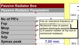
The settings is as follows: Mid-woofer has a 4th order LR low-pass filter at 3.5Khz and a Parametric EQ filters to counter for elevated response at 1.3Khz. The drop off at the lower end is because I crossed it over with the subwoofer at 80Hz and the 4th order LR high-pass filter is also embedded in mid-woofer's DSP parameters. The tweeter is a bit more complex. It consists a 4th order LR high-pass filter at 3.7Khz, a high-shelf filter at 15Khz to fix tweeter's top end droop and another 1st order high-pass filter at 3.7Khz. Together with the 10uF series capacitor it forms a 6th order filter crossed at 4Khz. This is because woofer and tweet have different rate of roll off at the crossover frequency and it must also be taken into consideration. Tweeter is padded down electronically at -3.5db so padding resistor is not needed. As a result the amp should have better damping factor to control the tweeter. Phase of tweeter is inverted, also electronically, to bring it closer to the phase of the woofer at the crossover frequency range. A delay of 76us is added to adjust the phase of the tweeter so it matches exactly the woofer's phase at 4Khz.

As a result, both drivers have steep roll off after crossover so woofers' break up and tweeter's resonance have been reduced to minimum. Tweeter at Fs of 2Khz is already -30db down and woofer's worst break up at 10Khz is off the chart (probably -40db down).

The next step is to fine tune the delay. I used the approximated 28mm tweeter Z offset as a starting point. Invert the tweeter phase (which is now as easy as editing one parameter in the dsp) then adjust the delay until I get the deepest null at the crossover frequency when running a frequency sweep.

For now it already sounds really good. Lots of details in the top end while not being shrill at all. Mid range is very tight and immediate. Along with a flat response and tight phase matching, it sounds a lot cleaner than before.

I have converted the CAD design into Linux Ecasound profile so if anyone is interested in doing Linux PC based DSP can look at them:

tweeter.ecp
# Tweeter driver
tweeter = -el:RTlr4hipass,3700 -el:RThighshelf,3,15000,1 -el:RThighpass1,3700 -eadb:-3.5 -ea:-100 -el:delay_0.01s,0.000076

mid.ecp
# Mid-woofer driver
mid = -el:RTlowshelf,5,80,0.65 -el:RTlr4hipass,80 -el:RTlr4lowpass,3500 -el:RTparaeq,-4,1300,0.8

woofer.ecp
# Subwoofer
woofer = -el:RTlr4lowpass,80

Audio-output section of mpd.conf:
audio_output {
type "pipe"
name "HDMI 5.1 DSP Crossover/EQ"
command "ecasound -q -z:nodb -z:mixmode,sum -a:woofer,mid,tweeter -f:s32\_le,2,44100 -i:stdin -a:woofer -
pf:/etc/woofer.ecp -chmix:1 -chorder:0,0,0,0,0,1 -a:mid -pf:/etc/mid.ecp -chorder:1,2,0,0,0,0 -a:tweeter -pf:/etc/tweeter.ecp -chorder:0,0,1,2,0,0 -a:woofer,mid,tweeter -f:16,6,44100 -o:alsa,hdmi:CARD=PCH,DEV=0"
format "44100:32:2"
}

The DSP software configuration I did was according to the blog by Richard Taylor: https://rtaylor.sites.tru.ca/2013/06/25/digital-crossovereq-with-open-source-software-howto/
The Crossover hardware upgrade I did was according to the article by Rutcho: http://rutcho.com/tweaks/01_bw_dm601s3/bw_dm601s3.html

Image 1: Original crossover simulated in VituixCAD
dm601s3_factory.JPG


Image 2: DSP crossover simulated in VituixCAD
dm601s3_hybrid.3.JPG


Update: I think I made a mistake of ignoring the Y axis offset between tweeter and woofer. I have added the measured 135mm vertical offset to the woofer and had to update the Z offset of tweeter and delay to make it work. The result is the tweeter delay has been modified from 71us to 76us. I have also removed a 1db Param EQ on the woofer which is more or less useless and only complicates things. I haven't done the actual measuring yet as I don't have a calibrated mic and I will try to get one soon.

One more thing I cannot enphase enough: Have a tweeter protection cap at all times! When I test ran this setup, the software configuration was incorrect so I ended up sending full range audio signal to both drivers. The tweeter sounded so loud and has more low frequency signal that I remember, until I discovered that the DSP plugins were not at the right place and the software couldn't find them! If I didn't have that 10uF cap in there my tweeters would have already been blown. I almost learned it the hard way so I will always have a cap in tweeter's signal line because the risk is not worth any sonic improvement of removing it.

I am pretty new to speaker design and measurement. I appreciate if people here can point out any obvious issues that I'm not aware of.

FS: Countless Audio OP Amps, Transistors & More

Old stock from inventory clearing of audio electronics company. Everything listed is in new condition and original bought from ELFA Distrelec, directly from the manufacturer, or Digikey throughout the years. Can ship anywhere but if you're outside the EU it might be pricy.

Mostly putting this here in so that someone who is looking for something specific can find it. For some of these components I've got several unopened IC sticks. Some I've only got a handfull left.

OP AMPs:

OPA134PA - Audio
OPA2134A - Dual Audio
OPA4134A - Quad Audio
LM10CLN - OP AMP & Volt. Ref.
LM324N
TLC2201CP - Low Noise Rail to Rail
MAX477 - Wide BW Unity Gain
EL2044CN - High Speed
EL2444CN - Unity Gain
NE5532D - Dual Low Noise Internally Comp.
NE5532P
UAF771TC
OPA27GU - Prec.
OP284 - Dual
TL061
LM324 - Quad
TS462CN
LM6142BIN - Dual
AD797 - Very Low Noise Very Low Distortion
TL071CP - JFET Input GP
TL072CN - Dual ^
TLE2062CP - Dual JFET Input High Out. Drive uPower
TLE2064CN - Qual ^
TLE2144ACN - 'Excalibur' Low Noise Prec.
LM6144BIN - Quad High Speed Rail to Rail
LT1028 - Ultra Low Noise
LM837N - Quad Low Noise
LMC6084IN - Prec. CMOS Amp.
LMV934 - BJT Pair
CA741CE
CA3080E - Transconductance Amplifier

Other stuff:

2SJ115 and 2SK405 Pairs - Audio Transistor
STP60NE06 - THT NMOS 60V 60A (have large qty, cheap)
V23092-A1012-A301 - Relays 12V, 400V SW.
MTD20N03HDL - SMT NMOS 30V 20A (have large qty, cheap)
LP2980 - 5V Ultra Low Dropout Reg. (SOT23-5)

I've got a lot more that I didn't list here, especially 74 series logic, if you're looking for something specific throw me a message.

Metal alloys, plating and tonality, sound signature

Hi all,
I am asking in general but particularly about IC sockets and pins - which alloys and plating provide the most pleasant tonality and sound signature?
They come in many variants (copper, beryllium copper, brass, phosphor bronze etc), and the plating whether it's tin, gold, silver etc has different thickness as well.
If anyone is knowledgeable on this subject I'd be grateful to have your insight.
Thank you

Small Speakers flat from 50hz to 20,000 khz, is it possible?

Newbie here, with some primitive questions.

Do not know too much on SPL, crossovers do not have any tools to measure stuff nor know how. Would need to pay someone most likely to design something and guide me thru the process.

Scenario, a pair of computer speakers (no 2.1), listening range is only 2-3 feet, do not care how they sound past 3 feet. Closed cabinet and stuffed, do not like ported speakers.

Two 3” drivers and a tweeter, could be 2.5 or 3-way, could be passive bi / tri-amped, or active bi/tri-amped not sure yet, open to all scenarios.

Most 3” drivers in the 84 - 88db SPL range roll-off around 120 – 100hz and at 50hz they are around 72db – 73db. That’s if the specs are not inflated. Was told that the specs at 1 meter are based on low voltage and do not translate to real life…not sure what it means.

If I want it to be flat from 50hz to 2000khz or 4000khz at around 80 db then cross with a tweeter, what is the solution without adding any gain via tone control to that 50hz-120hz range or any color to the sound?

Running two 3” in parallel would add 6db so I’m already at my 79db - 80db from 50hz to 120hz, but after that if I want to run only one 3” as mid range up to the tweeter.

What type of filter or EQ or solution is needed to run one 3” from 50 to 100hz at it’s full SPL, then cut it off either 6 or 12 db slope, then past that 100hz mark somehow the second driver drops by either 4 or 8db depending on the tweeter I choose not sure on the slope to avoid too much mud in the middle.

Can this be solved without DSP? And how efficient will it be without any peaks or too much mud in the low mid to mid section?

I can pick tweeter with low FS to match the slope of my 100hz so if its first order at 100hz I can probably push the mid range to 4000khz cross over.

In general if it’s off by 1,2,3, 4 dbs…. how much can an average human hear these 1-3 db peaks and valleys at such a close range of 1-2 feet, so if this problem is not solvable without adding gain or adding too much color with too much EQ adn have to live with minimal peaks and valleys?


Cheers.

Batting versus Acousta-Stuff

To refurbish some old transmission line speakers, I removed all the damping and installed bracing. I am now finding it difficult to replace the damping material as the line width is only about 3 inches by 13.5 inches. I don't have room to reach my arm in and evenly distribute the stuff. One speaker now shows about 3-5dB less output below about 50Hz. I am thinking I could more easily snake some 1 inch batting thru the line. My thought is to center the one inch material in the 3 inch dimension across the 13.5 inch width. I would put loose Acousta-Stuff behind the woofer (10") and then use about 3 feet of batting. That would leave the last 2 feet of the 6 foot line empty. This would compute to the same 0.5 lbs/cubic foot density as the original. I am Biamping with line level 150Hz crossovers and applying eq. Any thoughts on how this might work?

Satori wo24p-4 subwoofer/woofer stands

I posted about this awhile back but didn't really get anywhere. I am ready to put some money down and something built before my next kid comes (likely the end of my DIY opportunities).

I need to build a subwoofer that can play from 200hz to 20hz (150hz to 30hz is fine too). I need it double as speaker stands due to space limitations. My plan was to build something that could be used to turn a bookshelf (LS50M/Sierra LX) into a pseudo 3 way if needed, or use low order crossovers. I was planning on using a minidsp 2x4hd and crown xls 1502 for the woofer/sub. I have a hypex 252nc for the mains.

I was aiming for something 24-26" tall, and 10-12" wide. Approximately 50L or 1.75 cu ft plus or minus 20% or so. The plan was ported with the ability to seal the port. So I am targeting a QTC 0.707 for the sealed volume. I was looking at using Jeff Bagby's Woofer modules active but when I looked at the CSS SDX10, the official parameters are all over the place (likely from newer iterations or changes in manufacturing? . The audioexcite review also showed what I thought were inconsistent parameters to model with. So really I'm not sure where to go with this.

I am open to side mounting a12" driver but worried it can't play high enough and blend with the mains. I am also open to front mounted dual 8s, triple 6s, or single 10 inch drivers.

I was considering single:
SB satori wo24p4
CSS sdx10
Dayton RSS265 or bigger (not sure HO, HE, HF)

With the wo24-p, winISD shows with 25hz tuning a 3" port, 15inches long it gets me 15.5m/s air velocity at 20hz (-10db) with a 10v signal.

Does this look ok? or am I doing something wrong?

Since I am going active, with a minidsp and xls1502, should I just go sealed and correct it with dsp?

Thanks
Other suggestions are welcome!

OB Single Driver Eq

The idea comes from Papa's Equalizer presented by Dana on BA2021, talking about next Speaker Camp event. Nelson made a small Eq in order to give a bump on lower freqs, something similar as seen to ACN/B5.

PASSeq.jpg

So, as it could be very helpful for large OB speakers with single driver (only the fullrange), why not combine that cell with a variable notch like on B5? It will probably be amazing with big fullranges like AN or Lii (especially 15 and 18"). What do you think?
Cheers,
Vinz :cheers:

LifeO4 pure power supply MkII with battery holder + ES9028Q2M DAC HAT

LifeO4 pure power supply MkII withsoldered battery holders

Since I collected a lot of parts in the past for projects I planned but for different reasons
never started. I now have to clean up a little bit.

I have a IAN Canada LifeO4 pure power supply MkII Board with soldered Battery holders, only used some hours for testing.


140,00€, shipping included within EU, for other countries please ask for shipping costs. SOLD!!!

+ an unopened IAN Canada 9028Q2M DAC HAT for 35,00€, shipping included


20220508_192412.jpg
20220508_193057.jpg

busted the potentiometer on my Thorens TD203

hello. yesterday while trying to adjust the speed on my Thorens TD203 turntable I busted the 33 1/3 RPM potentiometer, now no matter how much I rotate it, nothing happens. I looked it up, apparently this happens a lot as the thing is very tender and the instruction manual makes this task look rather simple. after the 33 1/3 RPM debacle I unscrewed the controller housing and adjusted the 45 RPM potentiometer live, applying caution - this worked like a charm. so, the question is - can the 33 1/3 RPM potentiometer be replaced? also, could I perhaps get away with an affordable variable (bench) PSU? if I understand correctly, I need to adjust DC voltage the motor receives.

Photo 08.05.22, 14 59 15.jpg

Photo 08.05.22, 14 59 18.jpg

Photo 08.05.22, 14 59 32.jpg

whazza "Hyper Bass Reflex" ?

[ DIY ] Hyper Bass-Reflex Type Enclousures (for Single Driver) - DIY - Loudspeaker | Low-end Speaker Craft

tough to wrap pea-brain around this thing and how it might vary as the maker
works with little fullrange drivers - in the try below, it looks like a MLTL

Rough stab at a "hyper bass reflex" roughly using the "rules" below for the low qts B&C 12pe32 vs similar bulk reflex

rwmoi5f.jpg


Hyper Bass Calculations

hyper-04.jpg

Splitting Line Level for Subwoofer output?

Hi,

There is an older thread on this but not much detail.

I see some 2 channel preamp builds where the line input is tied in parallel to the subwoofer line level output.

The integrated amp I’m using does not have subwoofer output. The subwoofer does not have high level input.

So what if I just use Y-splitter on the line level going into the amp and then to the sub. If L and R are split but then combined to one signal to the subwoofer input, does that
not just combine the L and R going into the 2 channel amp?

I know the current trend, some use the minidsp but that just brings up the cost.

Opamp better than OPA2604 with big soundstage, and analog like sound?

Good morning. I'm looking for opamp better than OPA2604 witch big soundstage, and "analog" like sound?

But e. g. opa627 (in dual), lt1028 (in dual), lm6172 is too much speed, and are unstable in my tube-opamp hybrid preamplifier.

Anybody know beter opamp than OPA2604 with realistic "analog" like sound and good soundstage? (Without discrete opamp).

Thanks

High frequency roll-off

Hello everyone!

I have been doing some bandwidth measurements on a SE prototype amp, and I can see a decrease of the output voltage at higher frequencies, reaching -2.5dB at 20Khz (pure resistive load):
sweep_7vRMS_output.png
I have checked the levels at g1 of the output tubes, varies very little:
1Khz: 106Vpp
20Khz: 103Vpp
The only think left is the output transformer, which is from Aliexpress. Should I assume most of the high frequency roll-off is happening due to the output transformer? The amp is not using global negative feedback, below the schematic for reference.
SE_2x6P41S_6N1P_InputStage_v2.png
Link to the output transformer: https://www.aliexpress.com/item/4000899015634.html?spm=a2g0o.order_list.0.0.367c18020HinhR

Thank you!

Hafler 9130/Pro1200 circuit differences?

A question for fellow Hafler owners.

I'm modifying my Hafler 9130 amplifier, and have been comparing the schematics between it and the Pro1200. They both appear to be identical except (except for one resistor, R21) and the separate circuit that looks like the power supply to drive the front end.

I'm no expert on circuit design, can anyone suggest the difference between these two circuits, I assume the 9130 version is simply a "better" design and the Pro1200 version simplified to lower costs?

-Bryan

see attached

Attachments

  • comparison.gif
    comparison.gif
    70.5 KB · Views: 289

Your thoughts on a custom power transformer...

Hello everyone! I hope you can offer some advice?

I purchased a custom power amplifier from an older gentleman who designed a Class A stereo power amplifier based on the 304TL transmitter tube. The primary winding of the custom Hammond transformer shorted after several years. I spoke to the designer of the amp and he made some modifications for an updated transformer to replace the tranny that shorted with some better specs that can be dropped into place replacing the defective one (diagram attached).

I live in Canada and Hammond doesn't do one off's any more. I called another company called Electronics Craftsman in Ontario and same issue where they don't do one offs and require a minimum of 6 (Hammond requires a minimum of 10). I contacted Edcor in California and they said they cannot help. I know that maybe supplies are difficult to come by and many smaller companies might have gone out of business due to the pandemic? If anyone has any suggestions for me I would surely appreciate your thoughts and advice? The amp is only several years old and the older gentleman created something quite special here. More importantly the sound is wonderful and I have some great synergy happening within my system.

As a last resort, I may have to break down this transformer into smaller transformers and create a separate power supply unit and connect the two units through a cable.

I can't send it back to him for servicing as it was crated and shipped to me and we are several thousand miles apart. He lives in Calgary, Alberta on the West Coast and I live in Nova Scotia on the East Coast.

I have attached some files that will be of some use to you. This is a big transformer! The amp is beautifully crafted.

Attachments

Cary SLA-70B biasing issue

Hi All,
I recently acquired this Cary Audio SLA-70B and am really surprised at how good it sounds. I've had a couple of other Cary amps, and this one is the best of them. Anyway, the previous owner had broken a tube, and replaced it with a mismatch. I just plopped in a quad of cheaper chinese el34's to make sure it is up and running in good health. I went to bias the tubes, and discovered that the procedure outlined in the Cary literature doesn't work. The tube fuse has been completely bypassed somehow--you can remove the fuse, and the amp still runs fine. Upon internal inspection, it is obvious why--the fuse socket is disconnected. So that leaves me trying to figure out how to bias it. I have circled what I believe is the biasing pot in blue on the picture. I attempted to measure the current below the resistor that sits between the pot and where it is grounded on the capacitor, but could not get any current to register with the amp on and warm. Any guidance would be appreciated. I would also be interested in rewiring the tube fuse back into the circuit. --Jaybird
bias questions.jpg

Pairs of BG NEO10 and NEO3 for sale

Selling a pair of NEO10 and NEO3. I have used them in my previous open baffle setup hanged in main baffles:
1594396391990.jpg - Google Drive
NEO10's are sandwiched in their own baffles made from cork and covered with felt. In this setup they were flat from 600hz and needed no equalizing at all. I used 3khz crossover between NEO10 and NEO3.
NEO3's also have some felt on their edges (treatment for baffle edge diffraction) and hair rubbers for hanging them in main baffles.

Front and back pictures of both pairs:
neos-front.jpg - Google Drive
neos-back.jpg - Google Drive

I will send them as they are - with baffles and felt.

Price for pair of NEO10s - 450eur, NEO3s - 150eur for pair + shipping from Latvia.

Thoughts on "tracking tangentially to the groove"

Hi every one,

It is popular on the DIY Audio Website to use the phrase “tracking tangentially to the groove”, relative to discussions concerning tone arms.

I spent Monday afternoon downloading a Microscopic view of the groove in an LP and then tracing over the middle groove with a spline and turning that into a PDF drawing to illustrate the gross inaccuracy of the above phrase.

I used the same groove three times to show three successive positions of the stylus as the LP rotates.

The first position of the stylus shows it to be tangent to the groove at an angle of 11.82º CW relative to the vertical.

The second position of the stylus shows it to be tangent to the groove at an angle of zeroº relative to the vertical.

The third position of the stylus shows it to be tangent to the groove at an angle of 16.8º CCW relative to the vertical.

Assuming that the tone arm mounting hole is located vertically above the second position of the stylus, it would have to relocate itself 2.327” to the right of stylus position #1 to remain “tangent to the groove” and it would have to relocate itself 2.327 to the left of stylus position #3, to remain “tangent to the groove”. My hat would be off to the tone arm designer who could design a tone arm capable of accomplishing that.

Illustration No.1 shows a record groove at a scale of 927:1. I picked the middle one because it was suited best to make my point.

Illustration No.2 shows the same groove three times with the stylus in three successively different positions as the LP rotates. Tone arm pivot to stylus distance is: 9.200”.

(I don’t dare mention variable groove pitch which would make matters worse)

Sincerely,

Ralf

Attachments

name a good lamination glue for whole sheets

I'd like to bond two sheets of 3/4" all wood plywood. For 1.50" low inertia sub boxes. I use white LePages contracter glue for just about everything else. Is there something made more for this purpose? A bottle costs $15 and doesn't go far when I laminate with it.

What about construction adhesive applied with a half inch notch trowel? I thought I remember a guy using a two part adhesive. What do the pros use?

I don't want the thing letting go and vibrating when the sub is in operation. Which did happen before lol.

Two questions taming sharp treble on a set of Magnepan 2.7QRS & anyone ever used PA power amps with their maggies

I know the pa gear sonds like a dumb idea but the 2.7s are huge (over 6 ft) and im looking at budget ways to get some serious power to them. Im currently running a set of Monarchy Audio class a amps which are ok but obviously the big maggies would eat up some more power and put it to good use? is a pa amp an idea? i have balanced xlr outputs from my Nad dac so that side of it is covered and the other thing as mentioned above how do you tame sharp trebble in maggies in a medium room when you have a wife that forbids acoustic treatment?

Marti CLA40-H Modification Help ( First Mod Project )

Hey all, I recently bought a Marti Electronics CLA-40H and I'm going about making some aesthetic changes. I'm going to relocate a bunch of switches as well as get a new aluminum faceplate. This is my first big project! Any help at all would be amazing. The first three pictures below is the way it looks now and the last picture is the type of mod I'm aiming to achieve.

Marti CLA40-H Manual

Switch Type Changes & Relocation
There are two switches on the back that I'd like to change from slide switches to Potentiometers and move to the front. Any advice or help finding them would be much appreciated.
1. The first one Is a Stackpole DPDT Switch ( 3a 125vac, 1.5a 250vac, .5a 125vdc ).
2. The second one is a DPDT Switch from switchcraft ( 3a 125vac, .5a 125vdc )

On/Off Switch
There doesn't appear to be an On/Off Switch. Where in the circuit would I add that? And how!? Like the one below

On/Off Light
Like the picture below I'd like to add an On/Off Light. Where in the circuit would I add that? And how!?

Thank you for any help you can provide


1651980446296.png
1651980514211.png
1651980658123.png
1651981567031.png

what driver to use for Tham15 x4 from a single 20A outlet?

Im toying with the idea of trying to buy drivers for (4) Tham15 cabs, that will run off a single 120v 20A circuit.

Kappalite 3015LF neo (expensive)
Dayton PA380 (does this work?)

Any suggestions that keep them sounding good, dont break the bank, and meet the proposed power situation? Or is it just a bad idea?

Or should I buy the recomended drivers and run the amplifiers at half power?

Tannoy MG15 distortion problem

Hi, i just aquired a pair of vintage Tannoy monitor gold 15" from an uncle and i need some advices on a problem.

They were sounding good for a month until one driver started to devellop some kind of low mid distortion with bass notes and it also lost some bass it seems. The high frequencies sound very nice and don't seem to have any problem.

I narrowed it down to the driver, i also redid the crossover and contacts to verify it wasn't the problem but it hasn't cured it. ( i even changed the connectors and bypassed the crossover switches).


When i apply a small pressure with my finger at some spots on the dust cap or some spots on the cone, the distortion goes away and the bass come back sounding clear and very good.

Which makes me think it's a mechanical problem at this point and i'm pretty bummed..

The speakers have low usage and probably never were abused and I cannot see any visual signs of damage. (these are not the version with the foam surrounds).


Anybody has seen these kind of problems with Tannoys dual concentrics before? What are the possible causes? any fix?


I'm kinda out of ideas but my next step might be to try to rotate the speaker 180 degree in case it is related to the "spider sagging" as i have read here.


I realy hope i can revive these .. 🙁

Thanks.
John
Projects by fanatics, for fanatics
Get answers and advice for everyone wanting to learn the art of audio.
Join the Community
507,663
Members
7,883,221
Messages

Filter

Forum Statistics

Threads
405,982
Messages
7,883,221
Members
507,663
Latest member
The driver