Cyrus One Bias Issue

Hi,
I have a Cyrus One issue 07 TOG. I checked the bias recently and I have a channel measuring 5/6 mV. The other channel is ok measuring 8mV.
I have the service manual, and so I read there that if the value is low you must put a 220ohm resistor across the R81/R82 (This resistor should be 130ohm if I remember right).
Well, the strange thing is that on my unit the R81/R82 are those kind of jumper/resistors...here is a pix...
http://img857.imageshack.us/img857/5513/img0563vf.jpg
...if I check these resistors with my DVM i read 0....
If I put the resistor across the pins...nothing happens to the bias...
Anybody has the same issue as me?

Help needed -Electrocompaniet EC4.7 preamp

Hi ! This is my first post, so please forgive me if I violate any rules..

I'm about to repair an Electrocompaniet EC4.7 preamp. I have the theoretical and practical skills to do the job. But I have no service manual !! The ALPS motorized volume pot i scratchy. The replacement of the pot seems to be a simple soldering job. But the original pot is a non standard, hard to get, (low value), 2x5k version 🙁. Do any of you wise people know if this is a standard volume circuit (input at the "top" pin, output at the wiper and the "bottom" terminal is GND) ? or is it a more exotic circuit were the ohmic value is critical ? The amp is DC coupled, so I wonder if the low ohmic value was chosen to limit the impact of bias currernts in the following amplifier stage...

Best regards

SorenP

NAD 3103 burn out

Heres an interesting one

Had many of these go like this always the same and always R448 seems to be the weak link

but heres whats different about this one compared to the rest ive fixed

no blown fuses
no lamp on
and it still works, although a bit quieter than the other channel

question is:
why is it always the right channel that goes?

Attachments

  • 3130 burn out 1.jpg
    3130 burn out 1.jpg
    573.1 KB · Views: 82
  • 3130 burn out 2.jpg
    3130 burn out 2.jpg
    189.7 KB · Views: 78
  • burn out 3.jpg
    burn out 3.jpg
    180.2 KB · Views: 76

Naim Audio CDI CD-I CD1 CD-1 CDS - only impaired Skip > Operation

since more than 15 years I am not able to find this incorrectly behaviour by pressing the ">" button.
The player works fine in all other functions.

Only by pressing the ">" button (skip next) I observe an odd behaviour:
The arm starts strong to vibrate and goes several times the way from start to end and again back.
During this period and thereafter no commands trigger any response (even not "stop").

Only after switch off and again switch on - the player works fine by all CD's, and CDR's as long as I press only start. Amazing for me is, when I press "<" button, I observe also correct operation behaviour. The replace of the power amp (buffer stage) IC for tracking servo section and the associated electrolytic caps released no changes in the error image.

By replace (interchange) step by step all PCBs with help of a second model I was able to limit the error to those PCB, where the MCU is inside (mask programmable version from Motorola, type No ZC99685P), because this error went along by exchange this board in the second "CDI" exemplar.

I have forget some details in the meantime, but I will now risk a second service task.

Therefore I want to know at first a Philips/Marantz cd player or cheap hifi system/ghettoblaster/car-radio model, where also the ZC99685P from Motorola is in use as operating MCU (ZC99685P was custom made for Philips/Marantz but wasn't custom made for Naim Audio).

Who know that ?

BTW - are there other user's with the same unwanted effect as described above ??
I haven't read helpful advices about follow threads:

NAIM CDS-1
TDA1541A
http://www.diyaudio.com/forums/digital-source/207521-naim-cd1-no-audio-output.html
http://www.diyaudio.com/forums/digital-source/53132-naim-cdi-transport-replacement.html
http://www.diyaudio.com/forums/digital-source/155807-help-naim-cdi-cdm4-x-s-laser.html
http://www.diyaudio.com/forums/digital-source/165954-do-these-philips-cdm4-fit-my-naim-cdi.html
http://xing-v.blog.163.com/blog/static/148288684201171024718735/
http://xing-v.blog.163.com/blog/static/1482886842011720103352480/

Thank you very much for helpful advices.

Attachments

  • Naim Audio CDI CDM open top.jpg
    Naim Audio CDI CDM open top.jpg
    57.9 KB · Views: 480
  • Naim Audio CDI PCB rear top.jpg
    Naim Audio CDI PCB rear top.jpg
    141.7 KB · Views: 480
  • Naim Audio CDI PCBs front top.jpg
    Naim Audio CDI PCBs front top.jpg
    176.5 KB · Views: 565
  • Naim Audio CDI ZC99685P.jpg
    Naim Audio CDI ZC99685P.jpg
    92.8 KB · Views: 486

Ohm Walsh 3 crossover removal

Input clip broke (little lever thingie tabs inside), possibly hit by vacuum cleaner or something.

I have a spare set, threaded banana jack style question is, how to get the switch panel holding the x-over out with minimal damage?

Also, what’s a good replacement for the sound dampening blanket? It’s coming out in pieces.

Something like this work, or call Ohm service and ask if it’s available? (Couldn’t find on their site)

Frost King CF1 "No Itch" Natural Cotton Multi-Purpose Insulation, 16 x 1 x 48-Inch https://www.amazon.com/dp/B004Y6SX1Y/ref=cm_sw_r_cp_api_i_4NGS0WMGPDAY3TQW8V1W?_encoding=UTF8&psc=1

thanks.

norm

Philips CD Servo PCB "3104 103 3501.2 / 8204 055 01742" in which Models in use ??

I am looking for CD player models from Philips/Marantz, where the above mentioned servo unit is in use.
The only model, that I have found from Philips is the CD-670 - go to
http://egirland.blogspot.com/2013/03/again-on-philips-cd670-and-cdm2-cd.html

In the meantime I have find out, that this PSB's can be only recognized by the 4-digit number on the attached sticker mostly glued on the surface of TDA5708 and not by the above mentioned PCB numbers - check out the attachments in post #29 under
https://www.diyaudio.com/community/...that-use-cdm-2-cdm-4-transports.372412/page-2
Unfortunately from several PCB's sticker with this number isn't longer to find.

Thank you in advance.

P.S.: this isn't mentioned there:
http://vasiltech.narod.ru/CD-Player-DAC-Transport.htm

Attachments

  • cd670-servo.jpg
    cd670-servo.jpg
    143.8 KB · Views: 514
  • Philips CD350 CD150 CD670.jpg
    Philips CD350 CD150 CD670.jpg
    312.8 KB · Views: 689
  • Philips Servo 3104 103 3501.2, 8204 055 01742 solder side.jpg
    Philips Servo 3104 103 3501.2, 8204 055 01742 solder side.jpg
    220.8 KB · Views: 601
  • Philips Servo 3104 103 3501.2, 8204 055 01742 component side.jpg
    Philips Servo 3104 103 3501.2, 8204 055 01742 component side.jpg
    168.9 KB · Views: 544

Greetings from an Italian guy from Chicagoland

Good morning everyone.

My name is Manuele and I come from Rome (Italy). I moved with my wife near Chicago in early 2019 and since then our family has grown by two sweet addition 🙂.
I have been passionate about quality audio for about 20 years but it was only in 2019 that I started following this website.

I have never written anything so far but I took the opportunity to learn a lot from the experiences of other users until I decided to undertake my first audio project (a fully 3D printed modular line array speaker which I will talk about in a dedicated thread...).

This website is truly an endless source of inspiration and knowledge! Thank you all for your contribution in the name of good audio and DIY!

Regards,
Manuele

How can I pre-test my dim bulb tester?

Hi,

I just built this: https://audiokarma.org/forums/index.php?threads/dim-bulb-tester-build-and-how-to.808399/

And I think everything is fine. However, is there any real-world test (to ensure the wiring is 100% correct) I can do to pre-test it before using it to test my amp? Like plugging it into some cheap/durable electronic device and turning it on? Yes, this is a little paranoid, but more about better visualizing how it works and confirming for my education.

I did deliberately use the 'old' style switch and used the decora style outlet for...style 😀

Picture for fun, obviously this does not show the wiring!
Screenshot 2022-05-22 140333.jpg

Philips CD670

Hi all,

I'm new to the forum so sorry if this same topic is already hidden in the archives - I searched, but couldn't find nothing for CD670, except this:
"
jean-paul:
You know what, I have a "wrong" type in my collection. It is an old 1987 black CD670 with CDM2 mechanics. Laser is good and it is in good condition,
some small scratches. It has TDA1541 ( without A ) and SAA7220P/A. If you want it you can have it for shipping + packaging costs.
Send me a mail via the moderator if you want it. Could be a nice start in the DIY world. I am not saying that this is a perfect cdplayer but it has some qualities...
CD650 is the cheaper brother of CD670 AFAIK.
"

I bought Philips CD670 .
Inside the player:
Chipset SAA7210/7220/TDA1541,
Transport CDM2/10,
These two maybe for FTS function : MAB8441P/44166 ???,
Headphone amp JRC4560D,
I/Vstage and LPF stage : LM833N,
All regulators are 78xx and 79xx and there's one very strange 7906 (-6V).

Pro: it plays all (except for the ending too long disks- above 70min sometimes it skips or replay) , good DAC board, good sound quality for such a old and cheap machine.
Con: plastic case, slim size - not enought room for heavy mod's(separate PS), old version of the chipset.
Hard to perform the tweak - one half space(left) of the case sets CDM2 and transformer,the other half - above is the DAC board , and right under it is the set conroller PCB (and many cables and connectors between these pcb's),
next to this "sandwich" on the right side is set the PS board (for display).

After have read up some of thread's on the forum , I have idea how to implement these things:
I will disconnect muting transistors in the signal path,
To do a regulation on the positive and negative rails (+/-5 and -15) with TL431 shunt regs mounting closely possible to the DAC chip power legs,
Completely rebuilt the analog stage - swap the LM833 chips whit LM6172 - properly bypassing (same as DataSheet) ,
Cut out traces to these strange parts (maybe deemphasis) wired in parallel with feedback resistor an OP I/V converter stage. I'll leave only the feedback resistor(about 1.8kohm) with cap(about 2nF) to acts as 1st order LPF@44kHz .
Completely rebuilt the LPF stage(2rd order Bessel LPF@44Hz) - that would be enought (the player is ready) to simply try on TDA1541 in Non-os mode???

I would like to have the schematic for CD670, If you can , Please email it to me!
Or the schematic for cd650 or CD850 (or similar output stage, or similar PS model) ? After having a look at the otput stage schematic of Philips CD960 (finded it somewhere on the web), I can confirm that it's similar (analog out) as my Philips CD670.
Some of these schematics would be very useful.

Jean-paul and some of other experts - Would you help me please with some advice?

I apologize for my bad english.

FS:ACP+ (aca pre and headphone amp)

Sell my "Arlequin" version with premium parts: 9 per channel takman rey metal resistor (total 18 rey) + tkd pot 2511 (99 Eur value bought new).
Cosmetics as is but you can remove the thin transparent lid and remove the wood coloured turrets(fixed with 1 drop glue). The tkd pot is connected to board with solid core copper/silver military wire.
Sell it with stock ps. Price 330 or best offer. In case you want to spend 230eur only i will remove the TKD and reinstore stock alps.
Above prices need extra 25 Eur for shipping to Europe destinations. Fair offer will be accepted🙂

Attachments

  • IMG_20210911_184505_copy_600x600.jpg
    IMG_20210911_184505_copy_600x600.jpg
    65.5 KB · Views: 297
  • IMG_20210911_184353_copy_600x600.jpg
    IMG_20210911_184353_copy_600x600.jpg
    144.4 KB · Views: 300
  • IMG_20210911_184417_copy_600x600.jpg
    IMG_20210911_184417_copy_600x600.jpg
    93.7 KB · Views: 297
  • IMG_20210911_184403_copy_600x600.jpg
    IMG_20210911_184403_copy_600x600.jpg
    112.5 KB · Views: 286
  • IMG_20210911_184451_copy_600x600.jpg
    IMG_20210911_184451_copy_600x600.jpg
    111 KB · Views: 287

FS: ACA AMP Monoblocks

Selling this kit I built summer 2021. They have the selector to switch between Parallell and bridged or stereo.Stock components except the big cap that was replaced following forum advise for better sound and few prp and dale resistors were used as well as had them in house. Additionally has the forum group buy of the filter to clen ripples.Plays perfect, no hum neither any sort of buzzing.

Cosmetically just rated good as one scratch on one panel edge and small signs on one of the two amp lid. Moreover on bottom panel, signs of glue or biadesive when i wanted to fix spikes. They have the stock 24V smps. The squinchy sound at turn on present as well. DC setting tested today being 12.4-12.6Vdc each board after 20 mins run. I will include athick bridging cable with 2 nice quality copper spades, in case you will use it parallel mode.

Good shiny soldering with kester.

Sell first as monoblock set for 700 Eur or best offer + shipping inside EU(expensive as insured would be approx 30Eur). Paypal classic is fine. A fair and decent proposal will be accepted

Attachments

  • 20220518_141818.jpg
    20220518_141818.jpg
    586.1 KB · Views: 105
  • 20220518_141804.jpg
    20220518_141804.jpg
    592.7 KB · Views: 119
  • 20220518_141838.jpg
    20220518_141838.jpg
    446.1 KB · Views: 99
  • 20220521_135248.jpg
    20220521_135248.jpg
    768.3 KB · Views: 115
  • 20220521_082432.jpg
    20220521_082432.jpg
    630.2 KB · Views: 124
  • 20220521_090329.jpg
    20220521_090329.jpg
    442.8 KB · Views: 115
  • 20220521_094055.jpg
    20220521_094055.jpg
    472.2 KB · Views: 108
  • 20220521_135011.jpg
    20220521_135011.jpg
    656.9 KB · Views: 108
  • IMG_20210801_174449.jpg
    IMG_20210801_174449.jpg
    462.3 KB · Views: 101

:-) :-) :-) *** Hello diyAudio members, I need some help in many questions about LM3886 *** :-) :-) :-)

Hi there ,:wave2:
I'm Michalea and I'm a young girl who has chosen electronics as a hobby.😍
Please forgive my bad English, but Google Translator does its best 🙂😛

I've decided to do a bit with amplifiers, but I'm still having trouble understanding it.
Maybe you can help me to understand some things better and explain things more simply than it is described in the textbooks.

I bought a China LM3886 amplifier to do some testing and understanding.
I measured the circuit and have a few questions about it.

🤔
1) Why I need C1 at all when a cinch signal is already AC?

2) Are C1 and R2 a high pass? and how can I caculate it in a simple wise , which is the border frequenzes.
Which frequenzes makes sense to eliminate, e.g. under 60Hz ?

3) Why do the values for C1 vary between 1µF and 4.7µF in so many other designswith the same LM3886?

4) Why should C1 be made of foil and not electrolytic capacitor or ceramic, can you really hear the difference?

5) R3 and R4 is clear , the gain factor. But why do I need C2?

6) What is the R5 in only for? I've read some things that it would be better to have an RC (R8/C3) and RL (L1/R7) at the output so that the 3886 doesn't oscillate.
How do I find out the best values? ( see in circiut )

7) Then I saw that many have the supplement ( in red inside) , what is that for exactly? In the gain path?

8) Then I read some stuff about composite modes with an added OP, but I'll get to that later when I get the first things down.

9) What do you think is better for starting out as a youngster: KiCad oder EasyEda ?

10) I have a toroidal transformer with 2x 18V and 4x 6800µF and i got a light hum in Speakers, it almost sounds like the transformer
If I connect the earth of the 230V~ (gn/ge) to the GND of the circuit board, the humming becomes much quieter, but it doesn't go away.

11) If I have a good amplifier, what is the maximum V or mV that can be applied to output 3 of the LM3886 if the input is unused, i.e. open?

.... regards and from now on .....happy replying and writing 🙂

12 ) new on 29.01.2022 , phase shifting, see #14


:wave2:

Harman Kardon HK3270RDS relay sparking.

i got a used hk3270rds, 230v version. was dead, repaired flex cable, and placed missing grounding screws, amplifier started.

When pressing power ON key that puts amplifier in standby, the relay sparks and smokes. the relay doesn't activate until second power key (momentary switch) is pressed. amplifier works almost fine except that right channel is 15-20% lower than left channel. With speakers ON, as I pressed power key, volume slightly open, the right channel speaker got boom/static/pop etc.

What is the most likely cause of this?
is the relay activating on power ON (standby) key when it is not supposed to? sounds like it in the video.

When I press the momentary power on key multiple times, which controls the relay, sometimes it sparks sometimes it doesn't. I tried separating amp and tuner boards, the spark intensity is reduced, but not gone.

Service manual attached, relay smoke video in zip file attached.

Attachments

Question on Icepower 500A power connector wiring

Hi, building my first DIY amp. Planning for a 3 channel setup using a donor Parasound 5125 chassis & control boards, 500ASP + 2 ea 500A. I have the PS donor and the 500ASP in hand as well as all the harnesses. I'm waiting on the 500A's from PE to show up and I'm trying to get ahead with the wiring and prep work.

The 500ASP wiring is straight forward enough as far as I can tell. But I have a question on the power input for the 500A. Since I don't have the boards in hand I can't visually inspect or test for myself. The 500A datasheet and google fu seem to indicate that it only needs the 80V from the ASP, but looking at the connector spec, it says VP on pins 3,4 and PGND for 7,8.

So maybe I'm just overthinking this, but I'm a little worried about just trusting the documentation 100%. So according to the connector it says pins 3 and 4 get Vp, so which of these is correct:
1. The datasheet is whacked out and the hanger really should get 80V and 50V. In that case which pin is which?
2. The 500A does only need 80V and you should Y the 80V out from the ASP to both pins 3 and 4 on the 500A?
3. Pins 3 and 4 are connected on the 500A board and you only need 80V to one of them and can daisy chain the other hanger from the other pin?
4. I'm a dummy and am totally off base here.

1653340888934.png


On a side note, I found a guy with a very very cheap 5125 due to it having multiple failed channels. I was going to order a chassis for the build which was going to be about $150 plus I would need all the other parts. I got the 5125 for $100 shipped and after doing some troubleshooting I was able to save the control board and input controls, so I've been able to salvage the main power controls including the 12V trigger circuit and the auto on with signal. So coupling that with all the RCA connectors, output terminals and the nice spacious case I'm pretty pleased.

Appreciate any help with the question above.
Mike

Texas Instruments ADC evaluation module PCM4222EVM

image 1.jpeg


SOLD $114 shipped to you in a USPS Medium Flat Rate Box (CONUS only).SOLD

I bought this a few years back but never got around to a build. Brand new. Never used. Search on the gearspace.com forum as well as this forum for numerous discussions on how to DIY a state of the art ADC.

Users Guide here: https://www.ti.com/lit/ug/sbau124/sbau124.pdf?ts=1648138611241&ref_url=https%3A%2F%2Fwww.google.com%2F

“The PCM4222EVM evaluation module includes analog input and digital output circuitry with common audio connectors, providing a direct interface to audio test systems for measurement and evaluation.”

Mouser link: https://www.mouser.com/ProductDetail/Texas-Instruments/PCM4222EVM?qs=x9Fa6eo0USkoieE6GGZWGA==

Attachments

  • image 2.jpeg
    image 2.jpeg
    490.5 KB · Views: 120
  • image 3.jpeg
    image 3.jpeg
    448.9 KB · Views: 107
  • pcm4222evm-angled.png large.png
    pcm4222evm-angled.png large.png
    163.7 KB · Views: 58

2-Way Speaker Crossover Re-Design - Arcus TM 55 - Beginners Report

TL;DR: I recently found a pair of old 2-way Speakers, made by german manufacturer Arcus. As I first listended to them, I thought that they had beautiful bass and highs, but a recessed midrange. I tried to simulate the speakers using speaker simulation software boxsim ( http://www.boxsim.de/ ) and altered the crossover, starting with old parts from the scrap bin. After a few tries i ended up with decent speakers tailored to my listening taste.

Long Report - Intro

Since i was a youth i owned a pair of old, shabby looking Arcus TM 65 3-way speakers, that i considered to sound good at that time. Two decades later i already build a few DIY audio projects, like Salas UFS Phono Preamp and Randys Aleph 30. I felt that my old 3-way speakers where too shouty for my taste. I also want to tinker with active crossovers and bi-amping later on, that’s why i was looking for a pair of 2-way speakers. I found some Arcus TM 55 2-way speakers with beautiful wooden cabinets and bought them. When i first listened to them i was pleased, because the mids seemed to be less aggressive compared to my old TM 65. But soon i realised the mids where lacking completely.

Crossover Design Arcus TM55
Arcus datasheets states that the Arcus TM55 crossover frequency is 4500 Hz. Initially i did not believe that, because regarding their 3-way designs Arcus claimed crossover frequencies of 500Hz / 2000Hz with the same model of woofer and tweeter used.

I checked the crossovers on the TM 55 and i found a fairly simple circuit: one coil acting as a first order low pass filter for the woofer and one HUGE 7uF KP capacitor used as a high pass for the tweeter. Another small coil with a 4,7 ohm resistor in series is connected in parallel to the tweeter, maybe some kind of impedance correction?
So what we have is a very simple crossover, so lets check the values of the coils and simulate the speaker using boxsim for the sake of fun and learning!

Basic Measurements
I started with stripping the crossovers apart to measure the parts values using the simple GM328 Tranistor Tester. The big coil connected to the woofer measured 1,5 mH and the small coil parallel to the tweeter 0,58 mH. So the crossover design looks like this:

Weiche-original.png


I searched the internet for TSP and SPL graphs for the Vifa M21 WN-02 chassis and the Seas H174 1“ dome tweeter. I used REW to measure the impedance vs. Frequency of the chassis . With Vituix CAD i converted the graphs to asci text to make it usable for boxsim. With this data I created a first, approximate model of my 2-way speakers:


TM-55-FR-Weiche-original-1.png


First Simulation Results (Original Crossover Design)
The frequency response graph of the first simulation showed me why this speakers sounded quite recessed in the midrange. The graph shows a bass peak between 50 and 200 Hz combined with a huge dip between 300 and 3000 Hz. The highs above 4 kHz are obviously too loud compared to the rest of the frequency spectrum.
The crossover point seems to be at approximate 1500 Hz – one third of the claimed value in the datasheet. This results look quite disappointing regarding that Arcus was a big name in the German Hi-Fi market in the 1980s.


Next Steps
  • simulate alternate crossover designs using boxsim​
  • buy a measurement microphone to measure SPL vs frequency and response of the speaker in total​
  • use some old stuff to do a first try in crossover design​
  • build it and see if something changes​
  • learn and have fun​

designing multi voltage power supply

Hello,

I am designing a kind of audio preamp that will embed multiple modules.
For that I need to have:
  • 5V 3A (For RPi + USB DAC + TouchScreen)
  • 9V 1A (For Arduino)
  • +/-15V 1A (For RIAA preamp + Line Preamp)
For that what should be the best approach? Should I build a main power supply and add DC/DC rectifiers to provide the wanted voltage for each module? or should I build an individual power supply for each?

Regards

Maximilien

ayuda para reparar Kicker DX1000.1

¿Qué pasa amigos? esta vez estoy tratando de reparar y entender cómo funciona este amplificador. Es un pateador Dx1000.1. Mi problema esta en PS y en la etapa de salida, para empezar no se que ondas debo ver en la etapa de PS, entiendo que el uc3843b es el que maneja los pulsos de PS, pero no veo nada , solo algunos picos muy dispersos y solo tengo 1 mosfet de esta etapa en buen estado, se puede probar con solo 1 mosfet? ¿Hay reemplazos para estos? ya que son caros. ¿Qué pasa si me los pongo y se vuelven a quemar? Que señales debo observar en el uc3843b?... Saludos

Attachments

  • 20220516_215956.jpg
    20220516_215956.jpg
    581 KB · Views: 118
  • 20220516_215927.jpg
    20220516_215927.jpg
    596.4 KB · Views: 128
  • 20220516_215915.jpg
    20220516_215915.jpg
    648 KB · Views: 130

Amp construction?!

Why is it big different between channels???
Sorry for my bad english.
I have 4 Macrom synthesis1000 evolution amps, which I can adjust in an independent way. I have big difference in the channels. The left channel has more power, which the right channel has not. I mean the difference between left and right is about 3dB and it is a big difference. I know all amps have a little difference between gains but not 3dB! When I adjust the left channel about 11 o'clock and the right channel about 2 o'clock then I have the same power. All my 4 amps have exactly the same problems, which the left channel, have more power and right channel have less power. This amps have a switch in circuit witch I can disactivate preamp and crossover and in this mode the amp is driven with a fixed sensitivity of 1.1V and the phase rotates 180' only right channel. (This mode because the sound quality will be the same as really home hifi amps) Therefore is important the right speaker output connection must be inverted. Now, I have no control over my input sensitivity gain adjustment and crossover. Both channel have the same output power. Which in this case it is correct. But I don't got it, when I have the switch on built-in preamp which in this case I activated input sensitivity gain and crossover the channels is different... This amps cost $1500 each and are very expensive. Now, Macrom say it is normal because into the pre-amp section there is an inverter circuit between channels, this circuit allows the mono configuration into the output speakers which I have very difficult to believe.
Thanks alot if some guys kan help me.

Philips CD608 digital output broken

Hi, i have an old Philips CD608 that works perfectly except digital output.
Connected to DAC, that output is completely mute. Analog output instead is working fine.
Looking at service manual, this is the interesting part:

cd.PNG


SPDIF connector is on the lower side (BU2 -3 and BU2-4).
Service manual helps giving indication for troubleshhoting, as follow:

1653336549569.png


So i checked 3650 fuse resistor and it's ok. VDD is 4.9 V directly on PCF3523P pin 16 and 8.
Circuit 6568 is a BC848 transistor, It's not open and not shorted.
For testing i removed 3659 resistor to bypass any kind of Kill mute signal, but nothing changed with transistor base opened.
Bridge 3881, 3880 and 3889 are ok and not interrupted.
Resistor 3653 is 679ohm, so it's ok

Any other suggestion?

Are there any chances that the PCF3523P is not the culprit?
Thank you
Emanuele

KEF 104 to KEF 104aB mkII with SPICE

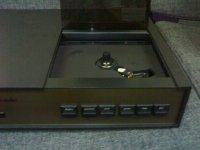
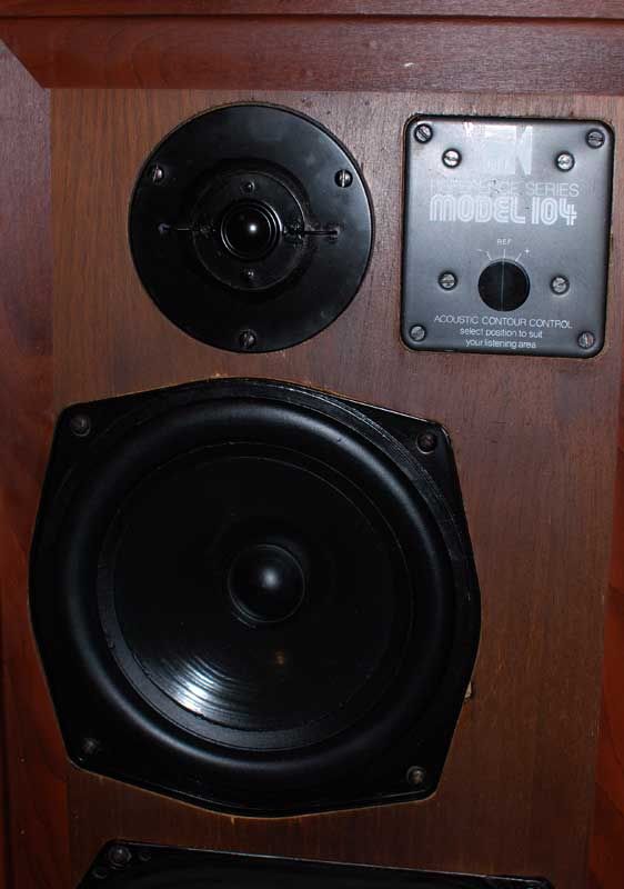
The vintage KEF104 series loud speakers still command a lot of respect today despite its age and simplicity in design. They have been many music lovers’ favorite speakers, and will continue to be much loved.

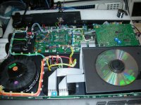
These 70s speakers have come of age and parts are no longer supported by KEF. If the speakers have spent time in humid conditions, it would require a complete overhaul for sure, after 30years in service. The crossover needs to be checked for component accuracy. And the drivers need to be checked for the correct mechanical and electrical properties.

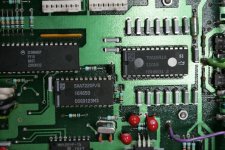
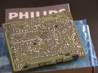
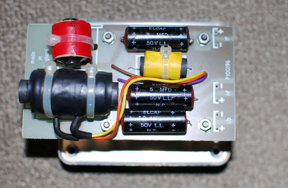
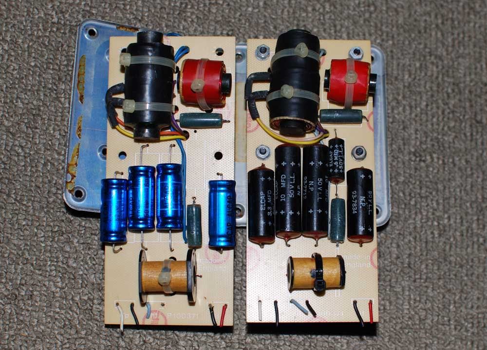
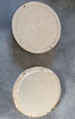
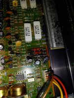
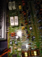
The crossover’s circuit board traces will have oxidation and corrosion after years of services. On close inspection and measurement, cross over tracks may have become thinner and pose a much higher series resistance in its path. In some cases, the corrosion may have introduced an open circuit.

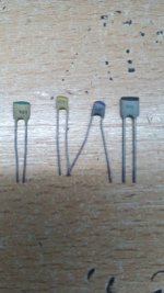
The old black Elcap black capacitors on the cross over will have to go, even if kept from new. I have measured many of such capacitors. Even good meters usually could not determine the component’s correct values (not less, but strangely, much larger capacitance).

XO104.jpg


The old Alcap caps may still retain its value after 20 years. Modern capacitors can perform much better. There has been discussion on the series resistances of the cap that affects cross over design. There appear to be two schools of thoughts, and both have their merits.

XO104aB.jpg


The simple, small ferrite coils may suffer from hysteresis. At high currents, or fast changing frequencies, any ferrite core will saturate magnetically and cause a non linear departure from the ideal behavior. This will manifest as distortion. The crossovers are placed very close to the driver units (behind the metal plates). Although there could be no significant magnetic coupling path, inductors are best free from strong magnetic fields. (The selector on the KEF face plate introduce contact resistances.)

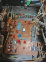
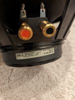
The internal wiring of these speakers is thin, and made of a few tinned cores. The fact that the crossover sits at the top right of the speaker, to facilitate selection of frequency responses, require a longer wire run. This adds to the current limiting effect of the internal wiring.

As such, the original crossover is best left as is, and a new cross over based on the old design be constructed as replacement. KEF did not put together a speaker crossover from a pile of loose parts. Individual parts must have been measured, put together, and then measured again, to meet a tight specification.

Therefore, to rebuild a crossover, we must at least have a RLC meter, SPICE software to determine the correct modern equivalent for replacement. We need to understand why the crossover was designed that way, and a measurement tool to meet that specification or goal.

Having said that, we may never be able to determine the original design goals KEF had. But KEF certainly had a design budget and there always will be a spread in specification during mass production. This is not building a pair of speakers from scratch, and we can get away from using an expensive full range SPL measuring device.


ORCAD SPICE SIMULATION

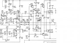
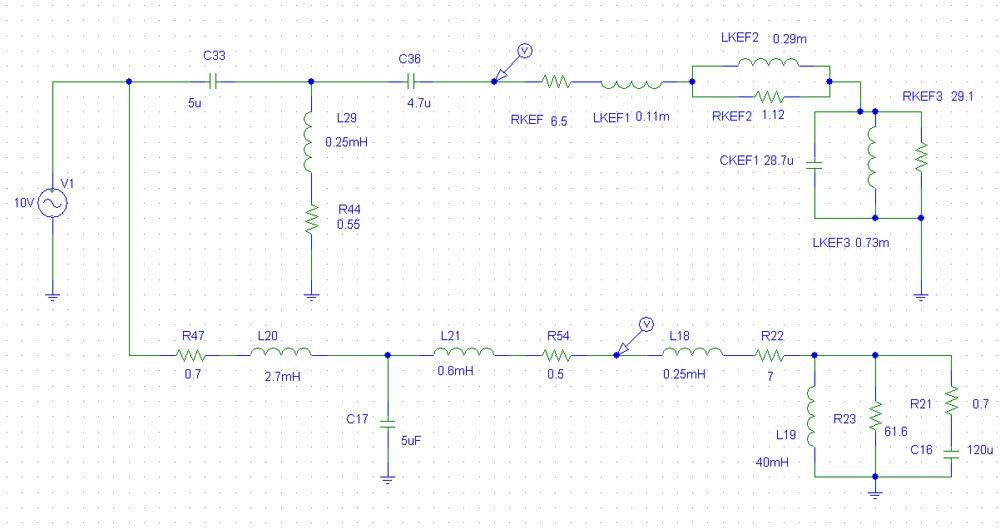
This is the original KEF 104 equivalent circuit in SPICE based on KEF’s published driver data sheets. Note that for the passive components during simulation, the inductor is always made up of an inductance and a series resistance (determined by measurements). Inductors have stray capacitance but ignored. Capacitance will have series resistance but ignored. Resistors will have series inductances, but small enough to be ignored.

KEF104-real-circuit.jpg


As the simulation is based on the equivalent circuit, this is only an approximation of the actual voltages appearing at the driver’s terminals. This is NOT the actual SPL output of the driver as the driver has its own non linear responses. The simulation studies the electrical characteristics in the frequency domain.

KEF104.jpg


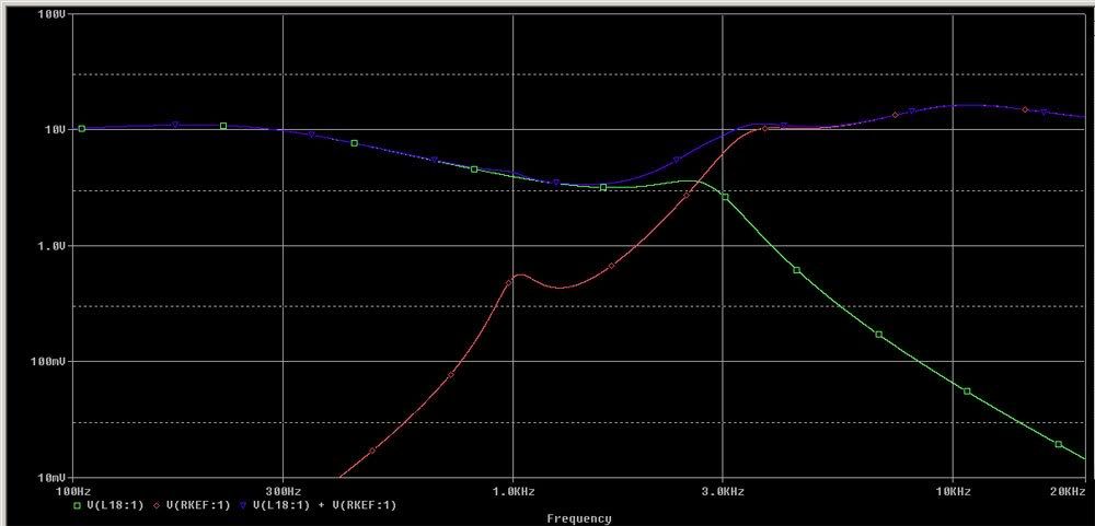
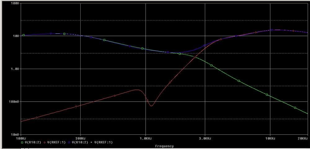
The red trace shows the voltage appearing on the T27 tweeter terminals, and the green trace the voltage appearing at the B200 bass driver terminals. The blue trace shows the summed voltage on the two drivers.

The red trace shows that there is no treatment of the natural resonance at 1.1khz for the T27A driver. There is a very slight hump at the 1kHz summed output (log scale) due to this 'resonance'. This is certainly undesirable.

The green trace shows a kink at the 2.5khz region for the bass driver.
The summed output shows that from 2.5kHz to 3kHz the transition is not smooth. However, the measured SPL of the drivers may be flat (as shown by KEF) due to the non linearity of the drivers.

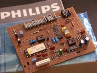
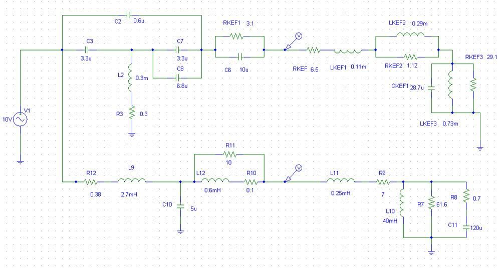
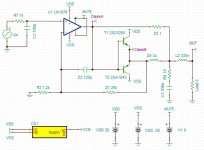
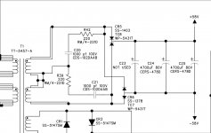
This is the KEF 104aB crossover.

KEF104aB-real-circuit.jpg


The introduction of a 0.6uf MKT type cap at the high pass, will result in a snubbing effect at the 1.1khz region, thereby attenuates the natural resonances of the T27 driver. The T27 will start to exhibit a falling SPL above the 10khz region, so the introduction of a paralleled 10uf with 3R combo will boost the output above 10khz, and flatten the resultant measured SPL.

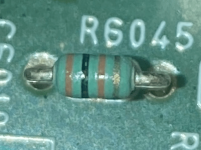
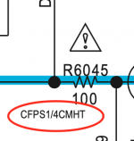
As modern caps have lower series resistance (low ESR), this can be compensated by a very small series R, so 3R in the high pass section can be selected to measure 3.1R or 3.2R to retain that damping effect. The value printed on the component may not be the actual value of the component.

The 0.3m inductor is realized by an air cored inductor with only 0.3R dc. The original ferrite core measured 0.55R dc. The resistance of the inductor determines how deep the attenuation of the 1.1khz notch would go. At 0R the attenuation will be close to full attenuation, ie, a short circuit. However, in a real component, there is always some resistance present. It is good to use MKT type for the 0.6uf cap that has a certain series resistance.

The choice of series inductance 2.7mH needs a low series resistance and low magnetic hysteresis. Ideally, an air cored inductor will have the least distortion as there is no core saturation. However, it is hard to find one air core inductor that gives 2.7mH and lower than 0.5R in resistance. The Mundorff Alconit or ferrite series offers a coil at 0.38R with much lower distortion at high current (high current wire).

The 0.6mH is bypassed by a 10R resistor. An air core unit with 0.1R is good choice.

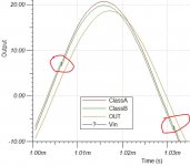
The simulation of the 104aB voltages with consideration of parasitic properties of the components is as follows.

KEF104aB.jpg


At ~1.1kHz, the voltage is snubbed and prevent the T27a from seeing the offending frequency. Due to the drivers own SPL responses, anything below 1.5khz will have very little output.

At 3kHz the knee kink as in the case of 104, is removed and the transition smoothed. This would make the speaker sound less intrusive.

The B200 transition is also smoothed near the 2-2.5kHz region. The 2.5kHz region determines the perceived sound quality of the speakers.

At 2.5khz, the summed voltages appear to be smooth and no exaggeration between the 2.5khz to above 3khz. This is a marked improvement over the 104 crossover.

The boost above 10khz for the T27 remains. The output is similar to the 104 crossover.

The analysis shows that the KEF 104aB crossover is tweaked to suit the T27a characteristics. KEF's acoustic Butterworth article might not had elaborated much in these technical details. The snubbing effect appears to be a KEF special. This same designs appears in later KEF models such as the Carlton series.

As such, it is not advisable to replace the T27a with any other driver without due consideration of the high pass circuit design. It would be better to source for a pair of used T27a (measured at 6.5ohms dc resistance) than to put in a pair of Seas or Vifa unit (resonant points can be anywhere from 900Hz to 1.2kHz, and different response curves).

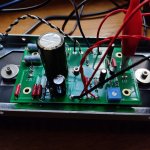
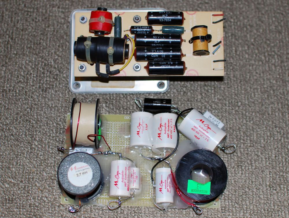
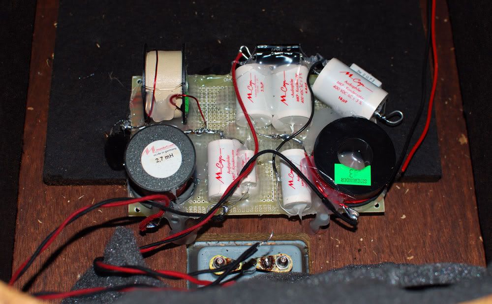
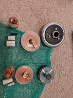
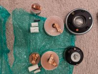
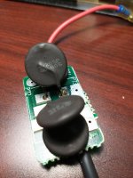
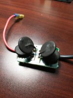
Real World Components

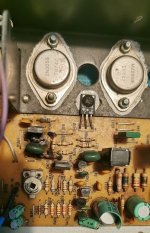
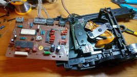
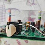
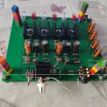
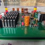
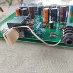
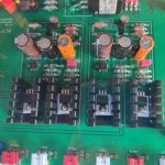
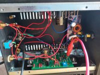
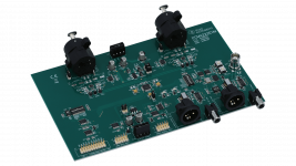
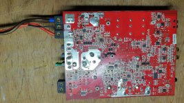
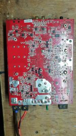
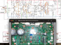
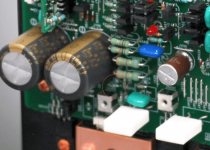
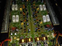
A new cross over is constructed using direct point to point connection of components. Components are secured on a FR4 board using hot glue. The final cross over is also placed near the input terminals, far away from the magnetic field of the speaker drivers.

XO1.jpg


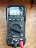
The main inductors can be of the Mundorff cored coil for its low series R and low hysteresis. The other two cores can be air core units but low series R as well. The inductors should be measured to ensure it is within 1% of the value stated.

The capacitors were chose to be Mundorff M caps (400-630V) types. The Mundorff caps are sonically superior to the Solen fast caps; both with a very similar cost. There is no need to bypass each cap with a 0.1 or 0.01uf cap, as this may result in a worse perceived high frequency. Individual caps should be measured for correct values.

The tolerance of the M cap is at 2%, at two extremes the values can be, in the case of 5uf theoretical, be 4.9u against 5.1u. This is not a lot, but we want to be accurate from the start. In the case of 10% tolerances, the deviation could be 4.5u or 5.5u, which will have significant shift in the cross over frequencies.

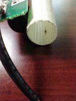
For internal wiring, it is recommended to use single core 18 or 16 gauge pure copper wires. As the crossover is nearer to the terminals, the overall wire run length is much reduced for the bass driver. The longer wire run for the T27a has little effect, as it favors a slightly higher series resistance. The coil inductance of the driver is much higher than the magnitude of the internal wiring. For the safety of the T27a, the 1 amp fast blow fuse should be in place.

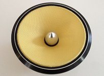
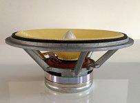
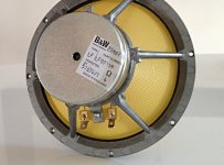
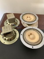
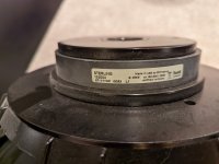
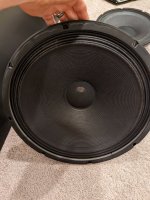
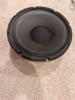
The B200 drivers can still be sourced occasionally on Ebay UK. The drivers should have the same series resistance s and deviate very little from the spec of 7 ohm dc. Due to age, the driver coil may see loose particles in the air gap, or the coil former may be deformed due to heat. This can be checked by slightly depressing the cone and check for rubbing of coil on the magnets. The damaged coil may be repaired, but not many technicians are willing to do it these days.

The bass driver and the passive radiator should have the rubber suspension cleaned and treated by Armor All. The rubber suspension may become dry and brittle in some cases. The change in compliance of the suspension will surely change the sound.

The drivers must be installed with sealing gaskets/foams so that everything is air tight. Check by slightly depressing the main driver, and see a small following excursion on the bass radiator. If the bass radiator do not follow suit, there is leakage.

XO2.jpg


The new cross over would require at least 100 hours to break in, mainly due to the capacitors. New capacitors will always ‘sound’ closed in, compressed when new. Breaking in over 100 or even 200 hours will significantly improve the sound. Therefore, initial assessment of sound quality when the crossovers are brand new will surely result in a wrong conclusion.

With the new crossover installed with the good drivers, the speakers can sound close to what it was designed for, and even better.

Comparing the original 104 and new 104aB, the mid range is less bloated and high frequency is less piercing, even thought the 104 have higher series resistance caps. Bass is more extended and the speakers sound a few classes higher. The new 104aB sound more refined, fast, detailed and still musical. However, the 104 still holds its charm, mainly due to its coloration which many find it pleasing.

Comparing the original 104aB and the new 104aB, there are more details in the modern version with the equivalent sweetness. Bass is less muddled. The speakers appear to have a ‘lower’ sensitivity, as the volume control can be turned a few notches higher. In reality, the speaker can play music louder, with much lesser fatigue to the ears. The most significant different will be the speed of the speakers. The speaker will be able to handle transients much better. Cymbals and percussion sound more clear but less edgy.

As the crossovers continue to break in with the drivers, sonic spatial illusion becomes wickedly apparent. Separation of individual instruments is improved, and vocals become more life-like. Sound stage layering will be more distinct.

FACE.jpg


In conclusion, the old caps in these old speakers must be replaced. There is a choice of original Alcaps or Mundorff depending on personal preferences. The old inductors can be replaced by modern cores that will elevate the performance of the speakers. The internal wires are too thin and relocating the crossovers is advantageous (foregoing the facility of inductance change for equalization).

A new cross over is not expensive to build, and the old crossover can be retained for comparisons, or for display. This is a worthy upgrade; the returns are much greater than buying a new amplifier or even a new pair of modern speakers.

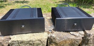
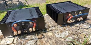
To fully appreciate the KEF 104aB, a high quality solid state amplifier of about 80-100Watts is recommended. Tube amplifiers either push pull or single ended above 10Watts can have good results as the speaker has decent efficiency. The source should be a good LP setup to fully demonstrate the capabilities of these classic speakers. KEF 104 can response up to 30kHz range. There are not many modern speakers that can sound as marvelous as these classics.

maximum output from Push-Pull 6CA7-EL34

From old tube manuals
*100 Watt output: Ep = 800, Eg2=400, Eg1= -39, Rpp = 11.000 ohm
*70 Watt output: Ep =500, Eg2=400, Eg1= -36, Rpp = 4000 ohm
*60 Watt output Ep=500, Eg2 UL-connected, Eg1 = -44,5 Rpp = 7000 ohm
*55 Watt output Ep=425, Eg2 = ? Eg1=-38V Rpp = 3400 ohm
*45 Watt output Ep=375, Eg2= ? Eg1=-32V Rpp= 2800 ohm
But is it possible to acheive 100 Watt output (and 800 volt at plate) with current production 6CA7-EL34-KT77 ?

Extremely Unconventionally Shaped Dual 15" Sealed Sub Enclosure Build

I have a 2009 Acura TL and it has a rather odd shaped trunk, the bottom is mostly flat with raised curves on the side, and I would like to run two Kicker 15" subs in it, according to my calculations each sub SHOULD have enough volume inside, however after some thought, I wondered, why haven't I ever seen any oddly shaped sub boxes before, is my build going to suffer issues of audio waves bouncing around incorrectly? I plan on adding braces and a divider straight down the middle to have them in their own separate enclosures, I've seen people say they've had issues with shared airspaces, but I'm wondering if the oddly shaped back (as it needs to match my trunk's shape) might have adverse effects on the waves as they come back.

Attachments

  • Enclosure 1.PNG
    Enclosure 1.PNG
    137 KB · Views: 280
  • Enclosure 2.PNG
    Enclosure 2.PNG
    103.5 KB · Views: 245
  • Enclosure 3.PNG
    Enclosure 3.PNG
    131.7 KB · Views: 265

active 3way I'm getting drivers for ...Scanspeak d2905/9500-Morel TSCM634-Scanspeak 32W/4878T..questions

I have the tweeters already & would like to use them. I want this a complete sealed system & modular top & bottom as easier for me to handle because of injuries. I am to use Hypex FA503 on each speaker set or Hypex FA253 bridged for tops & FA501 for bottom cabs. I have a dialed active dsp 3way system now & want to see if I can better it with DIY for fun. My questions are do you think these are good choice of drivers for the build.? I have looked at many drivers...I thought to go Purifi mid, but have always wanted to try a morel mid & I suspect it is good. Ill be using a NAD C658C & I have an Elysia parametric in system at all times, but can & most likely will be bypassed when switching to these speakers & using DSP parametric EQ via DIRAC. The SS bass driver was the tough choice but seems like it will do sealed & be clean to 300-375hz easy. If there is something major I'm missing or a better driver to use,please let me know. My listening position is 9' & listen to about everything you can think of via Vinyl & digital streaming .
Joe

Shorted amplifier speaker output wires playing music

Hi folks!

Sorry for intruding! Just registered on the forum to ask a potentially strange question.

I was turning on my vintage Aiwa 3070 Cassette Receiver not noticing that the speaker is disconnected and speaker wires are lying on the ground shorted. (I normally listen in mono, single speaker connected).

After turning it on in FM mode, as I increased the volume, I could very faintly hear distorted music playing from the wires (?!) and could make out some lyrics before noticing that the speaker is not even connected. I listened for a few seconds and carefully separated the shorted wires, the faint distorted music stopped.

To be honest, I only assume so and I'm not certain that the sound was coming from the wires and not from inside of the receiver or..?

I don't want to repeat the experiment on purpose. Nothing burned and the receiver is still working fine.

That got me curious. Could someone please explain what might have happened, and why the audio was (barely) playing from the wire without any speaker connected? How is that possible?

Many thanks!

ISO Phono stage impedance question

Anyone by any chance have schematic of iso phono stage, i want to change the input impedance.

The blue resistor on the left is 100r and on the right 10r, the wide area of the light green of PCB is ground plane. So i am guessing that the blue resistor is the one setting the input impedance, if that is the case is it a simple matter of changing this resistor?


InkedIMG_5602_LI.jpg
InkedIMG_5606_LI.jpg

Becker Brescia tube autoradio restoration.

I had been re-restoring this vintage autorradio made in Germany about 1960. This set has several years with me: it was gifted to me by Félix LU5DBX and was used few time and performs 9 pin tubes of the E series but one, the RF amplifier EC92: ECH81 mixer & oscillator, EBF89 IF & detector, EABC80 audio and carrier level detector, ECC85 relay driver and EL84 audio output. I replaced 'lytics with newer units and the EC92 triode is now a EF94 RF pentode rewiring the socket.

It has permeability tuning mechanism and a spring driven brass gear made to search stations according to 3 selectable strenght field in the front by a switch. The seeking function is called depressing the bar under the dial. A 3 fixed tone settings: normal, bassy and trebbly are available according to the position of the switch under the volume control knob at the left of the dial.

Only MW AM, no SW or FM.

The power unit uses a 115Hz vibrator that had to be opened and cleaned, the contacts was good. Very usefull data about vibrators and their habbits was found at:

https://www.cool386.com/msp/msp.html

and from a pdf free available from Mallory including designing of the transformer and waveforms. The rectifier is a Greatz bridge with selenium diodes in a block.

It is 12V by nature. Several capacitors was replaced by newer units using Siemens pieces trying to maintain german parts as I can. Also some brazilian parts as substitute.

The gear train was cleaned with solvent and oiled as it was solidified and dirty.

Note the newer 10mF @ 50V Siemens cap close to the vibrator, giving more clearace from it for better ventilation and aspect.
I added another 10mF @50V cap to form a pi filter with the internal inductor (original) and cooperates to reduce ripple in the vibrator circuit. Also, the cathode bypass is replaced by a newer unit 4.7mF @ 25V all from the Siemens trade to maintain german heritage.

The output stage is inside the vibrator power supply: EL84, matching transformer and coulpling network to EABC80's triode plate. The cathode biasing net of the EL84 doesn't return to ground directly but though secondary of the OT giving some few dB of negative feedback. The secondary has a tap, perhaps to accept 4 or 8 ohms speakers. The entire secondary is used to perform NFB. As a comment, there are two unused holes of the size of two new absent sockets. So, I suppose that it can accept another EL84 and (perhaps) a phase splitter to make a push pull output stage.

The restoring lavour is finished and the pet now has its new and own site at home.

Attachments

  • Front.jpg
    Front.jpg
    399.5 KB · Views: 284
  • Label 01.jpg
    Label 01.jpg
    331 KB · Views: 142
  • Label 02.jpg
    Label 02.jpg
    330 KB · Views: 172
  • Label 03.jpg
    Label 03.jpg
    333.6 KB · Views: 159
  • EL84.jpg
    EL84.jpg
    282.7 KB · Views: 149
  • PSU 03.jpg
    PSU 03.jpg
    302.5 KB · Views: 149
  • PSU 04.jpg
    PSU 04.jpg
    253.4 KB · Views: 150
  • PSU 05.jpg
    PSU 05.jpg
    279.2 KB · Views: 147
  • Antenna.jpg
    Antenna.jpg
    232 KB · Views: 143

High efficency three way with 15" FaitalPro and 1,5" dome tweeter: where to start

Hello everyone!
I recently grabbed a pair of FaitalPro 15FH520 15" woofers for very cheap, initially I wanted to sell those for a profit but since nobody in my area is interested I thought I may as well use them!
I may soon move to a new house which is gonna be bigger and will have room for a pair of beefier speakers, so I'm evaluating the idea of using those drivers to make a pair of towers (kinda like the Cerwin Vega SL-15) in conjuction with a midrange which I still have to choose, and possibly the Ciare PT383 tweeter which I already have. It's a 1,5" dome tweeter with a small waveguide on front.
I could use my 7 channel Harman Kardon AVR255 AV receiver to drive them fully active, or my other 5 channel Rotel RB985, the latter requiring some form of passive crossover.
My initial thought was to make a 110liter assisted bass reflex enclosure tuned somewhere around 35Hz, use the FaitalPro woofer up to about 5/600Hz and then cross it to either the FaitalPro m5n8, the Audax PR170M0 or the Ciare PNDI6.38MR. I don't know if I should get a compression driver instead of those.
I could get something else as well if there are any recommendations, as long as it's available in Italy and not too expensive!

I'm also aware that I could just make a 2-way and cross it with the Ciare PT383 tweeter directly, but I think there would be a tradeoff with power handling and midrange clarity.

I mainly listen to rock and metal, sometimes also folk and classical. I tend to listen quite loud on speakers and I prefer smoothness over detail.

6N6P (close to E182CC ECC99 6N30P)

The following 6N6P tubes are offered
- Novosibirsk plant, NOS, 1984 year, 28pcs available, 2,5USD per pcs
- Novosibirsk plant, NOS, 1972 year, 16pcs available, 5USD per pcs
- Foton (Tashkent) plant, NOS, NIB, 1964 year, gold grid, shining pins, military tests passed, 8 pcs available, 15USD per pcs.
- Foton (Tashkent) plant, NOS, NIB, 1965 year, gold grid, shining pins, military tests passed, 12 pcs available, 15USD per pcs.
Shipment worldwide by air mail with tracking possibility 10USD.

Attachments

  • 6N6P Foton 1964.jpg
    6N6P Foton 1964.jpg
    167.4 KB · Views: 535

Boss 4800 d

Hi, this amp is the same board as the ssl5000d is so similar the clones of this type 16 pcs irf44 n for the Psu and 12 pcs IrFb31n20d for the outputs, only diference is it has the driver audio circuit integrated in the main board, i have been working with this and found all psu fets blown an some gate resistances too, the sg3525 Was blown too, i changed the sg3525,one psu driver transistor Was blown, so i decided to change all four transistors, it uses 2 c1027 and two a1023, in another post i saw this transistors could be replaced with a1220 and c2690 so i replaced with this kind (i do not have c1027 and a 1023.thinking in a little improvement too in performance), one thing concerns me with doing this replacement, before i changed the Psu driver transistors in one grpup i have gate voltage ~5.4 volts, in the other i read 0 volts( driver transistor in short i think) with the replacement i got 8.4 volts in all Gates of the fets.

Can you tell me please if this 3 volts diference could in some way afect the performance of the Psu or even worse, overheat the fets and blown them prematurelly??


mpsa42 in the driver outputs has very low gain~3 so i replaced with mpsw42, Will install in this a little heatsink to help with the cooling, i Will try to sandwich the board too lubricate the fan, and i Was thinking in install little heatsinks to the New driver psu transistors to

As always i Will apreciate another coments from you, maybe some tip to improve the reliability of this particular model

Regards!

Reverseengineering an HK_Ottala

Power amps are something very close to my music heart.

I have quite a lot of them around here, Zen in different versions, Accuphase, own designs etc, and my favourite for the latest few years, an ML11, the last power amp Tom Collangelo designed, a magical little amp that can drive anything and equiped with quite a lot of power despite its modest sepcs.

As all Mark Levinson amps it has a certain sonic signature, leaning towards the darker kind of voice, never bright but with brutal transientresponse and attack when delivered such.

A while ago, rather long while actually, i traded a pair of JBL HF drivers and horns for an interesting amp, as i if i needed more of these.

Otala1.jpg


Utterly sophisticated design, B&O has something to learn here,.
But to the reason i wanted it. This amp is designed by Matti Ottala during his time as chief engineer at Harman Kardon.

The information i´ve got says it was designed as a prototype for the Citation XX project and the same story/rumour says 3 or 5 of this amp was built at HK workshop.

The amp is among the best i´ve ever heard with an extreme lightness combined with unbelievable power and transientresponse , a "sharp" voice but still not bright, drives anything i´ve loaded it with the same ease.

One major flaw, as an extremely wide bandwith amp it is very prone to amplify and distribute to speakers any wire or airborne signals in the vicinity.

Fabulous buildquality.

Otala2.jpg


So, i will dismante this amp, primarily for replacing wiring and also check/replace caps and find the right place to insert lp filtering to
avoid interference.

If there is interest in recreating this fantastic amp, it actually is just that, among the best i´ve ever listened to, ill start a thread reengineering the amp and se what we can end up with.

FS: New pair of B&W FST midranges from 802D

I have a pair of brand new B&W FST midrange drivers. Part number LF02359, from the 802D. They will ship with the trim ring and in the original box.

The FST midranges from the 800 series are one of the lowest distortion midranges currently manufactured and these sell for well over $300 each from B&W.

If you are interested please PM with a respectable offer. I will also ship overseas.

Thanks

Attachments

  • screenshot_524.jpg
    screenshot_524.jpg
    166.5 KB · Views: 310
  • screenshot_523.jpg
    screenshot_523.jpg
    144.9 KB · Views: 304
  • screenshot_522.jpg
    screenshot_522.jpg
    164.7 KB · Views: 316

some "noob" questions (frequency response/excursion vs. group delay)

Hello 🙂
I am playing arround with hornresp for some time now, trying to find the best enclosure for my DD Audio 608D2.
When i kinda understand now how to get what i want... i just realised... i do not really know WHAT i want.

So i got a few questions, you guys hopefully can answer me.
I got a pretty huge car (4.1m x 1.9m x 1.5m inside), in wich i want to use this sub in. So kinda low resonance and not that stiff chassis.

Lets start with the following image, how do i want it to look in my car if i want a mostly flat in car response? Do i want the sub to play up to 200Hz as seen in the images? Or is it better to crossover earlier?
Welche.png


So, more precise questions to this:
Do i want more like a curve at the end, like in "D", or more like a slope like in "A" ?
Do i want the upper end above 200Hz more like "C" going down continiously, or do i want it like in "B" with a as big as possible steep gap?


Also another thing i realised while simulating, since i am tuning below fs(38Hz), i get a lot of excursion OR group delay.
Is it allways low group delay vs high excursion / high group delay vs low excursion? Or is there anything i could do, do keep excurion AND group delay low?

Oh, one more question... my driver has a one direction xmax of 13mm and a xmech 32mm ... what would be a save value (hornresp displacement) to use it at low frequencys like 30Hz and below? (simulating at my amps rms output of 600w)
20mm? 25mm? Or should i defently stay at xmax?

Thanks in advance
Benni

Marantz PM-11S3: Replacing components: Should I follow the service manual or what is manufactured?

Hello folks,

I have a Marantz PM-11S3 that was purchased for parts with a bad right channel. I managed to turn on the amp to verify the left channel amp stage is working by measuring a 15mV idling voltage before the protection circuit puts the amp into standby mode. The right channel idling voltage was a whopping 9V before the protection circuit kicked in! I'm focusing on repairing the right channel amp stage. I am using the left channel amp stage and service manual as guidelines. So far I've found 7 resistors that were burnt, out of tolerance, the wrong resistor value, or in the case of R7053, broken (open). The back (foil side) of the right channel amp stage board reveals most of those resistors were replaced in a previous repair attempt, except for R7053. It is puzzling that some were replaced with the wrong resistor values. My plan is to replace all the resistors circled in red, and see what happens.

I have verified the driver and output transistors on the heatsink pass the diode tests (diode tests across BC and BE). I realize these Sanken devices are no longer manufactured and difficult to find, but for the moment I'm working under the assumption they are undamaged.

My question is in regards to film resistors that have been notated at "critical". Should I follow what's written in the service manual or what was actually manufactured?
The service manual clearly states:

"WARNING:
Parts indicated by the ! (in a triangle) mark have critical characteristics. Use ONLY replacement parts recommended by the manufacturer."

For example, on the working left channel R6045: The schematic calls for CFPS1/4CMHT, which is a carbon film flame-retardant resistor. In the photo, R6045 appears to be a metal film resistor based on carbon = orange/brown metal = green/blue. Also, I found a stock photo, compliments of Crutchfield, which shows what appears to be a metal film resistor.

Should I follow guidelines in the schematic or the manufactured part? Or are these actually carbon film resistors in blue/green?

As it turns out I purchased metal film resistors (eg MBA02040C2200FCT00) with slightly higher 400mW power rating before discovering this potential mistake. I purchased the exact match for R7053.

Any help is appreciated.

Attachments

  • Screen Shot 2022-05-23 at 11.28.06 AM.png
    Screen Shot 2022-05-23 at 11.28.06 AM.png
    1,021 KB · Views: 456
  • Screen Shot 2022-05-22 at 8.45.36 PM.png
    Screen Shot 2022-05-22 at 8.45.36 PM.png
    878.2 KB · Views: 449
  • Screen Shot 2022-05-23 at 11.35.34 AM.png
    Screen Shot 2022-05-23 at 11.35.34 AM.png
    114.1 KB · Views: 319
  • Screen Shot 2022-05-23 at 11.58.32 AM.png
    Screen Shot 2022-05-23 at 11.58.32 AM.png
    713.7 KB · Views: 261
  • Screen Shot 2022-05-23 at 11.45.47 AM.png
    Screen Shot 2022-05-23 at 11.45.47 AM.png
    8.5 KB · Views: 259

Crazy idea?

Right then guys and gals, feel free to tell me this is a bad idea!

I have a pair of B&W DM603s, I've played around with them already by removing the passive radiators, pictures attached. My ears can hear the difference, and measurements show improvements so all good.

And it got me thinking as I now have a free mounting place in the cabinet, could I introduce another driver? The answer to that is yes I can, no problem, easy! Except of course it's not that easy because having mounted it I then need to get it to work! And this is where I would need help.

I would need to keep the speaker at the same impedance, 8 ohms. And then there's the issue of what size driver to fit. My single figure IQ tells me that it would be sensible to fit another B&W driver of around 100mm or so, (existing mid/bass driver is 180mm).

The existing B&W XO is, (I believe), 3KHz, so my guess is the tweeter works from this up to 20KHz.

Have been looking at assembled crossovers but am unsure as to what to go for, and if I should go for two or three way.

Anyway, is this idea stupid? Ultimately I'm not going to do anything that is not reversible, and I fully understand that if I do go ahead that the speakers my end up sounding worse rather than better, (hence the reversibility). What I absolutely do not want to do though is risk the AVR; which for clarity has it's XO set to 120Hz, (work in progress with REW and MSO) and is driving two SB3000s through a MIniDSP 2X4HD.

Attachments

  • In-place.jpg
    In-place.jpg
    224.1 KB · Views: 111
  • Blanking discs.jpg
    Blanking discs.jpg
    419 KB · Views: 118

Separate subwoofer volume control

Separate volume control for sub amp?​

renderTimingPixel.png

Help please, this might be obvious and I may be overthinking it. I finished my Swan speaker build (loving them). Currently my setup is on my PC. I want to use the main volume on the Focusrite for the mains and the headphone volume control as a dedicated volume control for the Subwoofers.

USB > Focusrite 2i2 > Cleanbox Pro > Dayton SA1000 ( Bass AMP) > Nad 326bee (Main Amp)

The Focusrite has a separate volume control for the 1/4" dedicated headphone jack. The signal is full range though. What piece of gear do I need to strip down the full range 1/4" signal to an LFE or subwoofer amp signal (RCA preferably)?

Sure AA-AB31395 Noise Issue

Hello,

I built a battery powered subwoofer using the AA-AB31395 board from Sure Electronics. Two pcs Beyma 8 Ohm drivers are connected in parallel. Supply voltage is 60V. I use the Sure DSP for xover+eq.

Even with shorted input the amplifiers noise floor is horrible.

I should have read the datasheet better before ordering, noise floor is stated with 450uV.

DATASHEET

My expirience with amplifiers of this kind is very limited. So the only solution that i have for this problem is a passive low pass filter, an inductor in series with the speakers. the subwoofer crossover point is set to 110hz (DSP). i could use an inductor which cut's off everything above 150 hz, that would probably solve the problem, but introduce another one: inductors for 300-400W continous into 4R are very expensive.

maybe someone with more knowledge have another idea to solve this problem. any input appreciated.

thank you,
georg

MJK - A Method for Designing a Compact Back Loaded Horn Loudspeaker System

Has anyone read the MJK article "A Method for Designing a Compact Back Loaded Horn Loudspeaker System (added 06/21/12)" ?
What about any builds or comments?
Other drivers that can be used?

The only reference on DIYaudio is this one: http://www.diyaudio.com/forums/full-range/218332-smaller-fostex-backloaded-horns.html#post3135704
Also: why is the MJK account "Account disabled at member's request" ? 😕

For Sale Audio Tubes Tested

All tested on a very low mileage TV-2 tube tester which gives a representative value equivalent to a percentage of average NOS value of Gm. Minimum acceptable is given as denominator.
3 Amperex ECC88 A frame still test NOS:103,105;110,110;112,120/65 $50/all SOLD
Tung Sol USN CTL 6SN7WGTA with brown micanol base TV7 test 75,84/59 $20.
Sylvania tall 2 hole plate 6SN7GT TV7 test at 94,120/59 $20.
Sylvania JAN CHS 6SN7WGTA Chrome top 90,98 /59 $25.
Realistic Gold Pin Lifetime 12AT7 stamped "England" strong 90,96/69 $20.
Sylvania 12AT7WA 81,100/69; 12AT7WC 115,115/69; 12AT7 triple mica 71,77/69 $30/all.
5 X 1956 GE 12AU7 Big D Getter, sound good, test strong 5 for $20 (qty available.)
Amperex ECC83 Blackburn Mullard 87,95/67 $50 + ship SOLD
Amperex ECC83 Holland foil top 93,102 $50 + ship SOLD
USA 12BH7 grey pate halo 95,99/60 $15
3 X 5965 RCA 90,75/65 BECKMAN 98,100/65 SYLVANIA 100,100/65 $20/ALL 3
6 X Ericsson 403B 5591 All test NOS and close (probably NOS bulk pack) $50/all.
GE 6201 JAN 12AT7WB 89,93/69 $15
RCA 6072 12AY7 s-rod 80,82/60 $30.
NOS RCA 6201 black plate $25
GE 7025 grey halo 100,98/67 $20.
Sylvania 7591A, strong 92/65 $65.
PICTURES AVAILABLE ON REQUEST
willing to bargain
All + shipping. Satisfaction guaranteed. Will deal on quantity. Paypal f&f

Can / should I repair this toroidal?

Login to view embedded media
I received a used toroidal transformer but it was faulty.
It isn't a very expensive one. A dual 9V secondary from Farnells.
It is pre 1995 judging by the phone number on the sticker.
I have removed the tape and discovered a broken winding.
when I test for continuity, I get continuity from one end of the broken wire to blue and the other end to brown. (brown and blue being 240V primary)

I have continuity between both of the secondary wires and no shorts from one secondary to another.
(sorry that I am probably using the wrong words)
Nor any continuity between either primary cable and any of the secondaries.
I am aware that there might be other issues, but that bodes well right?

It wasn't packed all that well unfortunately.
But it seems like I have just the one breakage on the winding.
Is it safe/sensible/effective to effect a repair?

Or is this a supply of enamelled wire?
Thank you.

Rockford Fosgate T10001bd component identification

Hi everybody


Can somebody point out what are the CR5 + CR6 (TC7+TC8) in Rockford Fosgate T10001bd component as they are missing in mine ?

How there are +- 58volts rails when the minus is connected to one end of the cap and the plus to the other. I don't get that, There is no ground ?


Schematics attached.

Attachments

  • 5.JPG
    5.JPG
    88.7 KB · Views: 133

Tamradio Tamura Sony TC-500A Recycled Transformers

02.jpg

0-3 copy 3.jpg

0-4 copy.jpg

7-2.jpg

6-1.jpg

0-5.pngHi,
After a couple of Sony TC-500A tear downs I have recycled the Tamradio Tamura Nickel Output transformers and Sony Holey Basket FE103A Alnico speakers .

The Configuration consists of a 6J5 driver tube and Single Ended EL84 output tube running in Pentode mode 5 watts output.

The Cathode of the EL84 is set to 40mA with a LM317 regulator and a 22v Zenner Diode to set the Control Grid Voltage .

A EZ81 rectifier tube using a low noise Toroidal Power Transformer .

Power Supply Capacitors are all Film

Other parts are Dale Wire Wound , Kiwame Carbon , Caddock thick film Resistors and Russian K40Y signal capacitors .

Hook up wire is mainly Kimber Teflon OFC Copper .

Input RCA and Speaker Terminals KLE Low Mass Copper .

The Sony Holey Baskets- Fostex FE103A / Alnico speakers are housed in a copy of the Humble HiFi Solo 103 cabinets, http://www.humblehomemadehifi.com/download/Humble Homemade Hifi_Solo-103.pdf

The System has excellent resolution and a very natural sound, Vocals have a real lifelike quality as do musical instruments , probably due to the Tamradio Vintage Permalloy Output transformers and high quality parts.
I prefer this amp to the Audion 300B for naturalness of human voice also pictured here .

Lower bass frequencies can't be expected without a sub woofer .

The Chassis is from Hammond as are the DC chokes which are dual rail past the first two smoothing capacitors .

In summary a great sounding second system from recycled parts .

Attachments

  • 9-1.jpg
    9-1.jpg
    40.9 KB · Views: 672

Toroid downside and solutions

A downside to a toroid transformer is the possibility of a surge if the power happens to be applied at the zero crossing point of the AC mains.
One solution is to use a thermistor in series with one leg of the primary. This is effective, but it requires that knowing when the amplifier is turned off the thermistor will have to cool before the unit is turned back on. That's easy enough to keep in mind, but what about brownouts? These interruptions are too short to allow a thermistor to cool, so their intended purpose in this application is negated.

One possible solution is to employ an UPS (Uninterruptible Power Supply). Thoughts? Any other solutions? (Yes, i'm aware an EI transformer could be employed instead.)

Loud crack noise when sample rate changes

Hi folks,

In my digital audio chain I have a "problem" since years which I would like to get rid of: When listening to music from different digital sources or when the sample rate of the music changes I'm getting a loud "crack-crack" noise out of my spekers and the initial second (or so...) of the new track is lost. The latter I can live with, but the cracking is annoying me as I heard that this is not happening in other systems.

My digital chain:
Streammagic 6 (SPDIF)
Funk Tonstudiotechnik CAS2-V3SE SPDIF switcher
Mutec MC-3+ Reclocker (SPDIF > AES3)
DEQX PDC-2.6p HD (AES3 > Analog)

How would I find out the crack source?
Once I know the crack source, how do I best mute the cracking? (Inserting a mute circuit would definitely be an option...)

My suspicion is that one of the systems in the chain does not "mute SPDIF" (if such a thing even exists...) during switching/synchronising to the new sample rate...

I hope and would be grateful if someone could shed ligh on the issue, so I understand it better, and propose potential solutions.

Thanks and Regards,
Winfried

Problems on Chinese Power amplifer Module

Hello All

I have a problem on a Chinese amplifier which uses 2SC5200 and 2SA1943 transistors the final transistors were purchased from Farnell and are of the same category of HFE (o) the amplifier works but the loudspeaker safety trips as soon as the we push the volume I try to cool the input transistors but nothing changes. Does the problem come from the too spartan loudspeaker security or is it possible that the amplifier has a breakdown? I wired 2 modules the 2 do the same thing. Thanks for your help.
S0fe36bf0a72847b4b5b339de0fe733738.jpg
Sc23a7729f38446e3a9e9ce9953b68783q.jpg
speaker-protector.jpg

Singles: Hawthorne 15" Sterling Silver Iris, Hawthrone 10" Silver Iris

I have two single drivers that were previously used as front/rear centers in an all OB surround system.

15" Sterling Silver Iris (15" woofer with cast frame, ridiculously good Radian tweeter) - $150
10" Silver Iris (10" woofer with cast frame , standard tweeter) - $75
Sterling Silver Crossover for 15" (brand new, never soldered) - $50
Sterling Silver Crossover for 10" (brand new, never soldered) - $50

Attachments

  • PXL_20220524_110659866.jpg
    PXL_20220524_110659866.jpg
    313.6 KB · Views: 59
  • PXL_20220524_110709951.jpg
    PXL_20220524_110709951.jpg
    474.2 KB · Views: 62
  • PXL_20220524_110217892.jpg
    PXL_20220524_110217892.jpg
    753.7 KB · Views: 80
  • PXL_20220524_110235026.jpg
    PXL_20220524_110235026.jpg
    682 KB · Views: 52
  • PXL_20220524_110616994.jpg
    PXL_20220524_110616994.jpg
    570.1 KB · Views: 54
  • PXL_20220524_110625213.jpg
    PXL_20220524_110625213.jpg
    281.2 KB · Views: 49

FS: B&W FST Midrange Drivers (Yellow Kevlar)

I have some of these units for sale. They are the classic yellow drivers that were used in the B&W 800 series for years up until the latest Silver "Continuum".

They are extremely sensitive (around 93dB/W) as a result of the lightweight Kevlar diaphragm and large vented Neo motor.

If you are designing a 3-way speaker and want a very low distortion unit these could be for you! Bandwidth 200Hz - 10kHz.

Let me know if you are interested

TC

TDA7492P sounds softer through aux than bluetooth

I have a SANWU audio TDA7492P (the red one with aux input and buttons) which works perfectly through bluetooth. But when I plug in a 3.5mm jack it instantly becomes quieter. Even if I play from bluetooth and connect a cable that goes to a device that plays nothing. Generally, playing through the aux cord is quiter with any device that I've tried (always testing on 50% volume). My TV (and laptop for some reason) don't have bluetooth and if it's an easy fix, I don't want to buy an adapter.

Brum noise from a Mark Levinson No.532

Hi! I wonder if some one have a god guess about this one.....

When POWER is pressed the amp sounds like BRRRrrrrrrrr.........
Stand by does not change it.

VERY audible for half a second and then barely audible. Never disappears....
It never affect the sound to the speakers. They are dead quiet.
My guess is that it could be some mechanical vibration but where to start looking….?

Maybe I’m wrong….anybody?

kicker 354xi resistors looking toasty

so i was given this kicker 354xi amp in trade a few months ago and I have actually really been enjoying it, I was using it in my off grid cabin powered by agm batteries, i normally bridge the rear channels and drive mtx terminator (I think) 10 inch sub and various random speakers on the front two channels. lately ive been using a meanwell lrs-350-12 to power it in my camper.

anyway the amp works and sounds great, i really like it, I popped it open to look at it cause i was curious amd noticed that a few 220 ohm resistors seem to be getting a bit warm. R103, R120, R313, and R320. I googled around and saw that a few other 354xi boards were burnt in the same spots.

is there something preventative I should do about this? put some new resistors in? a cooling fan? heatsink?

Attachments

  • 20220410_221357.jpg
    20220410_221357.jpg
    601.3 KB · Views: 110
  • 20220410_221406.jpg
    20220410_221406.jpg
    665.5 KB · Views: 110
  • 20220410_221418.jpg
    20220410_221418.jpg
    656.3 KB · Views: 122

Using Existing XMOS Controller with added AK ADC

Sorry for an off topic post, but this thread is closest to my question I could find.
I have an AK4495 DAC with XMOS U8 usb controller that I bought on AliExpress. It is really good after replacing all caps and an op-amp in LPF.
I am looking for a high quality USB ADC to record from a microphone. Since I already have an XMOS U8 USB controller I am wondering if there is an easy way to connect AK5572 or 5394A ADC to it over I2S. I could make the ADC board myself since Asahi Kasei gives reference design in their data sheets but I do not know if it will work with an XMOS controller. Xmos driver in Win is registered as a playback device. Does it mean that for recording with Xmos controller I will need some special driver? If somebody could give a simple answer It would greatly help.

Help Identifying MOV

I am trying to troubleshoot my Parasound amplifier that keeps blowing the main 15amp fuse shortly after power is applied.

I "think" I have traced the problem to this board: When I turn on the amp, I hear a slight sizzle/crackle sound. One time I turned it on and a small amount of smoke came from this board. Note the brown spot on the insulating jacket.

This board runs between the power plug, the main fuse and the power switch. The amp is almost 30 years old so likely this board and components are that old as well.

Can anyone identify this? Are the components in fact MOVs? They do have some bulging spots and on one of them the black insulating cover has come loose.

Will this Littelfuse serve as a viable replacement?

Thanks.

Attachments

  • IMG_20220430_080407902.jpg
    IMG_20220430_080407902.jpg
    156 KB · Views: 184
  • IMG_20220430_080421106.jpg
    IMG_20220430_080421106.jpg
    161 KB · Views: 173
  • IMG_20220430_085020252.jpg
    IMG_20220430_085020252.jpg
    170.5 KB · Views: 174

Fender Champion 110 Problem

Hi,

I'm new to this site and was hoping to get some help.

I have a Fender Champion 110 and it would not become silent when the volume was turned all the way down. At first I thought this had to do with a bad connection to ground (later I found out I just needed to clean the pot). Anyways, I went in and noticed that somebody had already moved around the jacks. The joints looked kinda bad and I wasn't getting any continuity on the traces by the external speaker and output jacks. I was able to add some solder to the joints to gain continuity. Now the amp has a loud squeal. Kind of as if it were oscillation.

I tried reversing what I did. There was a hum from the amp and not the speaker. No sound from the speaker at all.

I checked the 1n4003 diodes and they were okay.

There's no solder jumping across the traces either.

If anyone can offer help that'd be great. Any pictures of the traces by the jacks would be helpful too.

Thanks!

2 pairs - Hawthorne Silver Iris 10"

SOLD!

1 pair - Hawthorne Silver Iris 10"

Good morning all,

I have one pair of the 10" Hawthorne Silver Iris Coax's (plus a spare) that were previously used in a home theater setup (surround) (no enclosures). Looking around the for sale ads, I think $150/pair with standard crossovers is a good deal. I also have the tweeter and crossover upgrades for an extra $150/pair (pricey parts!!).

I'll get pics up soon. Items are located in Stafford, VA (22554), but can deliver in the DC metro area as well. Shipping is extra.

Stubbed horn questions / usable bandwith, phaseshift, crossover

Hello guys,
when simulating different enclosure types with my driver, i endet with a stubbed horn now.

I got the Space for it in my car (roughly about 200l), and since it is a van, i guess my roomgain to start relatively low. My main goal was to have a as flat as possible frequency response down to ~20Hz.
Since i have no experience at all in building subwoofers or any other hifi components, i got some questions:

  • First... will this be a usable subwoofer? What do you think about it?
  • could i use it WHITOUT any high/lowpass filters, just the way it is now? (Excursion is ok at my amps max power)
  • does it make sense, to use a subwoofer up to like 200Hz, like it would be in this case?
  • how would the crossover for it work? At wich frequency should i crossover, and how would that work with the delays/phaseshifts in the upper frequency?
Power.png
overview.png
delay.png
phase.png


Thanks for the help 🙂
Benni
Projects by fanatics, for fanatics
Get answers and advice for everyone wanting to learn the art of audio.
Join the Community
507,641
Members
7,882,316
Messages

Filter

Forum Statistics

Threads
405,947
Messages
7,882,316
Members
507,641
Latest member
Gousty