2SC5200 & 2SA1943 Buying Recordation’s

Has anyone got any recondition where to buy Genuine 2SC5200 & 2SA1943 Mouser and Profusion have neither in stock, AliExpress I have 6 of these hear nice magnetic backs and get dam hot that’s the good ones the bad ones take themselves out and the divers.
Amazon and eBay is again pot luck, RS have them in stock works out quote expensive but they are Toshiba, but I understand they are no longer made so how do they have them I can’t believe RS would be fakes.

TemaadAudio 12'' Uni-Pivot Tonearm Kit

I have a un-assembled as new TemaadAudio 12'' Uni-Pivot Tonearm Kit that I will never get around to use now. makes up to a high arm of around $1,500 (depending on the wire you use)

Price US$260-00 worldwide postage available, would swap for MC cartridge

Photo 1 is what kit contains

Photo 2 is same arm made up from L/Heaven

Attachments

  • 1006211048.jpg
    1006211048.jpg
    557.4 KB · Views: 270
  • Lenco Wizard.jpg
    Lenco Wizard.jpg
    101.4 KB · Views: 255

Amp power issue, PSU or Amp protection?

Hi Guys,
I got 2 problems probably connected:
I recently built a sub and I also put together the amplifier with some aliboards and a Dayton LF.
The Amplifier is a L15DSMD irs2092 and the PSU is a 350W +-50V +12V (More 250W than 350W...).
Here the links to the actual parts:
PSU
Amp
Preamp

Whitout preamp:
When I start cranking the volume it goes into protection with a rather low volume. Everything shuts down and turns on again and keeps doing it and the volume is quite low compared to the main speakers (Small and not very sensitive JBLs guess 85/87 Db)
So low volume, barely usable, have to set the sub channel to +6db to have a balanced output with the mains (Sub volume 100%)

With preamp:
I also have a preamp board (Actually 2 and it happens with both), but if I try to connect them even more problems kicks in as it goes into protection right away without even music, if I disconnect the power to the amplifier or to the board everything stays on at least without or with low music. If I disconnect the Load everything stays on.

In your opinion is it a problem related to the amplifier or to the PSU ro what?
The sub is an Infinity 1240W 12inch 4 OHM in a 35l sealed (the Dayton is currently set as pass trough).
The input signal is from the sub channel of a Cambridge Azur 351R.

Thanks for any hint you can give me! Don't really know where to look!
I'm a mechanical engineer, so I'm crap at EE...experimenting and learning...🙂

D.

Swap the caps

I have a repair shop. Just answered another email from a new customer telling me that he thinks his "amplifier just needs the capacitors replaced".

While, yes, sometimes indeed the caps need a swap, it's silly how the general public seems to believe that every audio issue in their world is caused by the need for a "caps swap." Where did this begin? How can we stop this?

conditions which people have tried to convince me can be repaired with a caps swap:

"my amplifier won't turn on" - caps swap
"one channel is really distorted" - caps swap
"smoke came out and then it sounded really bad" - caps swap
"I heard a pop and now there is no bass" - caps swap
"I found this speaker outside and thought it might still be good" - caps swap


Stay tuned for part II: "just needs a little solder"

adjustable inductors maintenance etc.

"I had an issue with an am tuner the adjustable potentiometers they were very hard to move but I was able to get the iron material cap unscrewed and found a lube on the underside of the cap so I took some of the lube under the cap and put some onto the treads of the iron cap then screwed the cap back on and now no more issues it moves freely now but, I was wondering if anyone knows the specific type lube used on these types of components etc. (non conductive perhaps silicon type lube not sure) the iron caps can very easily break when they get stuck etc. without the lube on the threads etc."

Kicker 06ZX700.5 Subwoofer Channel Repair Help Please

This is my first post on this site have gotten lots of great info in the past on here. Today i got a kicker 06zx700.5 that had a non working sub channel. amp would power up green and play on the 4 channel side. so i took it apart found one of the subwoofer side power supply fet blown along with the 100ohm resistor replaced with new irf 3205. before i did that i checked all resistors and gate supply voltage everything was good. now with the parts replaced amp goes into protect checked all ouputs and output resistors and everything is ok. but i did notice if i removed the card (pas315-02) that it would power up green and stay that way but once i plug it back in it goes right back into protect and kinda goes in and out of protect every 4-5 seconds. im not a pro at this stuff but i have repaired 40+ amps in the past with success and never had problems after that but kicker amps get me every time hoping someone could help me please and thank you.

Tube preamp / OTL headphone amp build thread

Hey, usually I post only images of already finished devices here but I thought it could be nice idea to begin a build thread and add news as it goes 🙂

I am building tube OTL headamp, but this one is special in a way that I planned it the best I could in terms of parameters with lots of additions like inputs switching, analog meters, some modes etc. It will be just analogue, very simple, no MCU. Only "digital" switching thingy is raspberry pi on one of the inputs for DLNA, but its powered on demand. Its just a concept and not sure how it will evolve and what the parameters will be, but simulation looks very promising 🙂

I am in very begining and gathering all resources atm but for now I will share the schematics what it's all about...

PSU
There is +190V LM317 regulated PSU for tube preamp supported by high voltage mosfet. Very simple and very quiet 🙂
Balanced +-12,6V slow turn on regulated PSU by LM317/337 is for tube filaments and VU log amp part OPs
+5V "digital" PSU is just super simple LM1085. Powering all the relays and some cmos. In case of DLNA input selected it is powering rasp pi zero w with boss mini dac.


PSU.png


AMP
I have built some really very good performing OTLs in past, but this time I wanted to do it even better. For this purpose I needed bigger open loop gain to get more feedback and get THD as low as possible. Begins with ecc83 tube diff stage with common cathode CCS with 2N5551 controlled by TL431 reference. Negative voltage for CCS is taken from filament regulated -12,6V psu regulated even more by 7909. Next stage ecc83 again looks like srpp but its not, its normal amp stage with anode load, well tube ccs basically, to get exactly 1/2 voltage on anode for next direct coupled wcf stage by 6n6p. To get the best out of it I will use big PP output cap, it does not need to be super big, a few tens of uF are enough as there is plenty of negative feedback compensating for loss on low frequencies. Thanks to diff input, its very convinient way to implement nfb and play with it. I would like to try switch feedback input divider and change gain based on headphones used. Expected performance is very low THD even into hard loads such as 150-250R headphones...


AMP.png


Inputs / Outputs and extras:

Because of safety there is going to be DC protection circuit with turn on delay to omit any DC on output while powering up and also during playback. As mentioned in intro there is going to be simple input switching as well as DLNA wifi playback support from rasberry powered on demand. There is going to be remote in/out feeds in case of powering up power amps or turning on this preamp by remote source, such as +5V from PC USB f.e. A bit mess for not-involved one but here it is 🙂

IOs.png


Front panel stuff:
On front panel there will be small PCB with all the switches, LEDs, VU meter log amp etc. Again a bit of mess but makes connections much more cleaner between front panel and main board. Analogue log VU amps are not my invention but inspired from different service manuals and somehow combined to work for my needs...

PANELbrd.png

More to come (hopefully) soon...
  • Like
Reactions: Junm and dreamth

Help fine tuning a ProAc 3.5 clone

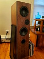
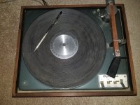
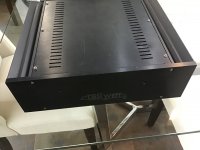
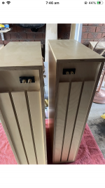
I'll try and keep this succinct but a little background: Last year I built what might be termed some "inspired by" ProAc 3.5 clones. 98% of the time: best speakers I've ever had! 2% of time, less so and I'm looking for some insight.

I say inspired by because:

1. I put a great deal more effort into taming cabinet resonance than the originals, which were fairly conventional (all sides use multiple material layers and the front and back walls are thicker than the originals).
2. I used drivers that were as close as possible, but knowing that ProAc had their own drivers customized, it was never to be an identical match.
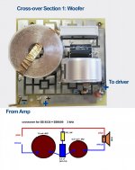
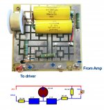
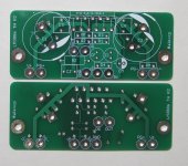
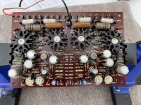
3. I used very high quality cross-over parts and the general design is based on some classic ProAc 2.5 clones (ProAc claimed they used the same cross-over in both the 2.5 and 3.5). On paper the cross-overs I used looked be a good match for the drivers: two Scanspeak 18W 8545k mid/woofers and a ScanSpeak Revelator D2905/9900-00 1" Tweeter. (Note that the design shows the 8535 but both drivers have the same reccomended cross-over point among other similarities)
FB_IMG_1651585047274.jpg

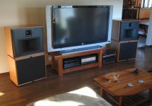
The Good: In almost all cases these things sound great! Tight clean bass down to 30hz (though they start rolling off at 40hz). Mids sound warm and natural and plenty of detail in the highs. They can rock hard and yet a female vocalist with guitar sounds delicate and nuanced.
20220716_135431.jpg


The Problem: At the very upper end of the 8545K's range they are getting some signicant breakup during very particular loud passages. Think: the upper register of a piano being pounded on top of a jazz band that's really jamming out. Or certain sections of a classical symphony or many voices in a choir.

It's not coming from the tweeter; it's absolutely the mids. I'm not over driving the speakers, and the amp is Krell KAV300i (fully class A with plenty of power). I have another system in a different room for surround that, although good, is half the system my dedicated stereo is, and I don't get any noise at all (it also doesn't sound anywhere near as real either).

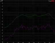
This issue is not all the time either. I can listen to a dozen albums and not hear a thing, but then, certain tracks (or sections) will make it jump out like crazy. Also, when I do test tones: nothing seems obviously amiss there either, but when it shows, it's impossible to ignore.

Intuition says it is almost certainly that the mid/woofers needs to be crossed over at a lower point. Is there a way to do so without a complete redesign? I assume there must be? I know there are software Sims to use for stuff like this, but to be honest I'm not sure where to start. Plus, this is already built... Thus if anything immediately jumps out to those here with more experience, it would be a huge help!

Thanks!

Note:
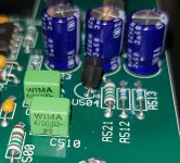
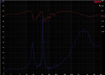
Probably the tweeter cross-over point will need adjustment too of course, but as they are on seperate boards I'm inclined to address one thing at a time (if possible). Below is the cross-over for the tweeter (again the driver spec.s out as compatible but is a higher end model).
PSX_20220716_144351.jpg

Attachments

  • 20210721_200029.jpg
    20210721_200029.jpg
    358.3 KB · Views: 163
  • Crossover Wiring-Woofer.jpg
    Crossover Wiring-Woofer.jpg
    283.3 KB · Views: 143
  • PSX_20220716_144351.jpg
    PSX_20220716_144351.jpg
    1 MB · Views: 145

Amp HF distortion - only with covers on?

This MOSFET AB amp - PMF2150B - measures fine with the top and bottom covers off, within the limitations of my gear anyway. (theres a small DC offset issue, 6mV one channel 40mV the other, but I'm pretty sure I can fix that by replacing the input differential transistors with better gain matched pairs).

BUT When the top and bottom covers are back on, the sine wave on the scope goes really thick and fuzzy, while still visually resembling the fundamental, and on the basic (8bit?) FFT my scope has there is a huge spray of noise around 20kHZ and 220kHZ, and a way high noise floor. I can literally remove the distortion while unscrewing the covers. This is compared with a well functioning Yamaha MX1 AB amp I have here.

Hopefully it is something simple - the service manual under high frequency distortion suggests a few things, one being heatsink coupling capacitors - I checked the heatsink coupling capacitors and they measured 0.01uf where as the schematic says 0.1uf, could this be the problem? Or is it just lack of apparent EMI/RFI filtering on the Perreaux amp power supply vs the MX1? I have both schematics here and can post if need.

20210611_172806.jpg

12" drivers for multiple sub setup

What are the suggestions for high quality small 12" closed subs?

For a long time I have had interest in trying a 4 sub setup as proposed by Geddes/Welti//etc.

My interest is music exclusively (not HT).

The subs should cross at 80Hz over to 15 inch "low-mids" (Altecs), which are crossed at about 700Hz to a horn with a compression driver.

I am not looking for extreme low frequency reproduction, but the lower they go, the better. SPL should be enough to keep up with the Altec+horn.

Finally, the subwoofer enclosures should remain small, I'd say below 90l/3cft, and closed boxes are preferred.

The LAB12 seems to do the job, but I am not sure if there are better alternatives.

Blown IGBT in an EL34 Tube Amp Kit - what is the cause?

I built a simple single ended tube amp kit based on EL34. The PSU contains a capacitance multiplier circuit. After a few hours playing, the IGBT chip blew (shorted). I need to figure out what causes the failure before buying a replacement part. Can someone help to identify the issue or suggest changes to the circuit?

The circuit of the PSU is below. The actual supplied part for Q1 is FGA25N120, which is a 1200V, 25A NPT Trench IGBT with build-in protective diode. It was mounted on a heat sink. The size of the heat sink is 22 X 35 X 15 mm.

Aliexpress EL34 SE PSU.jpg
IMG_2320.jpg


When the unit was working, voltages at C, G, E were 314.5, 305.2, 292.7V. The amp consumes about 140 mA. So the IGBT is dissipating around 3 watts.

My questions are:
  1. Why choose IGBT while other designs use MOSFET or Darlington? Is IGBT less reliable or I just got a bad part? Should I switch to a MOSFET?
  2. Does the design dissipate too much heat or cannot handle start up? I tried to turn on heaters for 15 seconds before turn on the power, but not always so.
  3. Is the heat sink too small? If so, how big should it be?
  4. Every capacitance multiplier is a bit different. However, is this one a good design? I found the use of three 220 uF capacitors in this circuit is a bit excessive. In fact, I now took the IGBT out and connect the capacitors in a simple CRCRC filter. R1 is 82 ohm and R2 is 37.5 ohm. I got B+ at 301V with only 0.5 mV hum at the speaker output. Looks like the capacitor multiplier is not even needed.
Appreciate your feedback.

Sanyo G3001 Hum/Noise

I've inherited this system and it had very noisey pots and a hum/white noise that gets louder when the volume is turned up. I've cleaned the pots out and they're fine now, but the hum and hiss is still very present. I've tried a full re-cap of the amplifier board, but I don't think that has helped anything. There don't appear to be any transistors on the amp board, as it is all handled by one large STK audio IC. There are a couple transistors on the input/tuner board, which i've given the old tap test and freeze spray treatment, which made no audible difference to the noise or hum at al.

Anyone got any suggestions of what I might try? I assume the unit didn't just always sound like this...

Amek console: strange behaviour on some channels

Hello again.
Last Friday, I was at a friends studio while he was making a life session recording.
He send the mix through 2 additional channels to his recording device. On channel had the gain set much higher than the other in order to record at the same level. He told me that sometimes he has to mute the output and then turn the gain up to maximum and then back in order for that channel to react. It is as if the channel has to be exited in order to function properly. I remembered that the same sometimes happens in my home stereo: I have to give a good push of volume in order to get both left and right speakers to give the same response.
Any idea of what is going on? Maybe a pot that is dirty or a filter cap that is dry?

Total Pro TP40 Servis Manuel

I'm trying the zvs flocked arc method with eht transformer, unfortunately, when the probes touch the water, the spark goes away and because the water is conductive, it draws excessive current...
With the Total Pro Tp40, this arc-forming process is very successful. I need to do this, what's inside as circuit? I will be glad if you can help me how to do it.
Login to view embedded media

Attachments

  • totlptro.jpg
    totlptro.jpg
    36.3 KB · Views: 87
  • Zvs.jpg
    Zvs.jpg
    72.8 KB · Views: 89

Heath IT-3121 Curve Tracer Legael to copy Schematic

I have reverse engineered and drawn a schematic diagram of the circuitry in my Heath IT-3121.
I release this document into the public domain.for the use of anyone interested.
No guarantees of accuracy, fitness or safety are made relating to use of this document.
Caveat Emptor.
No fees may be charged for reproducing this document in any form beyond the cost thereof.

Have fun with it.
The IT-3121 has served me well, especially in the realm of restoration of high power amplifiers.
Not only has it been a good tool for matching parts but also for selecting new devices when originals are no longer available.

At some point in the future, I may release an updated schematic which would include alternative components for those NLA devices as well as improvements to the functionality of the instrument.

Tom Garson, Aural Technology, Ashland, Oregon

Attachments

DIN SME 90 degree adapter for phono cable?

Hi, can I ask for your help in finding a DIN SME 90 degree adapter for my phono cable (in lack of a better expression, I'm not a native English speaker)?

Some more background:
My tonearm has a standard 5 pin DIN SME connection. My previous phono cable had an angled DIN SME socket for connection to the tonearm, which is required because there is very little space underneath the plug in the turntable chassis. This cable broke, and while I'm waiting to receive the new one (it's being built but will take a few more weeks), I'd want to temporarily use an old but good Cardas cable I have - but this has a straight DIN SME connector, which protrudes way too far and as said doesn't fit in the turntable chassis...

Is there some sort of 90 degree adapter which I could use temporarily to connect my straight cable? So kind of an angled adapter with a 5 pin DIN SME socket on one side for connecting to the tonearm connector, and a similar connector on the other side for plugging in the phono cable.

Here's an image of the angled connector of a Pro-Ject phono cable
Winkel.jpg

- looks to me a bit like it's attached to the connector of a straight cable. which you could pull off and use for my purpose. It likely isn't, just to clarify and visualize what I'm looking for. Doesn't have to be metal (because of the weight), could just be the plastic that the plugs are usually made of, or something similar.

Does anyone know where I can get something like this?

Where to buy a SMD Hotplate in Europe?

Where do I get an affordable rework hotplate in EU?

The UYUE946C Electronic Hot Plate on e.g. Aliexpress looks good for the purpose. Anywhere in EU where these are stocked and there will be no problems with toll?
https://www.aliexpress.com/item/100...616585665959504803e44e7!12000025288761522!sea

SMDs are getting smaller and smaller and some of the newer power devices hade pads on the underside so need an improved solution to soldering iron and hot air solder station

Poolside Speaker Box Design and Build

Scenario:
Currently I have a Bluetooth two channel amp driving two ‘rock speakers’ in the back yard. It makes decent stereo sound when we’re splashing around in the pool. I have been given 4 Pyle 5.25 car speakers. I’d like to build two speaker boxes, each housing 2 of these Pyle speakers. These new speakers would replace the ‘rock speakers’ when we are outside and connect to the existing wiring to the Bluetooth amp. I do not plan on leaving them outside 24/7. As I’ve never done this, I’m posting to this forum for insight, guidance and the practical opportunity to learn about speaker design.

Given:
Grace Digital BTAR513
2 x 37 watts RMS at 8 ohms
2 x 50 watts RMS at 6 ohms
2 x 70 watts RMS at 4 ohms
Frequency Response: 20 Hz – 20 KHz

PL53BL 5.25” 200 Watt 3-way speakers
100 Watts Rms / 200 Watts Max
1'' High Temperature ASV Voice Coil
20 oz Magnet Structure
1'' Neodymium Film Dome Midrange
3/4'' Piezo Tweeter
Impedance: 4 Ohm
Sensitivity: 89 dB
Frequency Response: 100Hz - 20Khz

Speaker Displacement: 0.14lts
Speaker Box Volume: 0.35 ft^3

Questions:

Electrical – Wiring two speakers in series the total Ohm load is additive. 4 + 4 = 8. Wiring in parallel, the load is divided. 4 / 2 = 2. As the amp doesn’t support a 2 Ohm load, I’ll most likely damage the amp wiring the speakers in parallel. Can I add a resistor, then wire them in parallel? Should these two speakers be wired in series? Should I just use one speaker?

Mechanical – The calculated speaker box volume for one speaker is 0.35 ft^3. If two speakers will be used, is the volume additive 0.70 ft^3?

Mechanical – I’ve emailed PYLE for a spec sheet (including Fs and Qes), but I do not expect a response as these speakers are made in China. Without that knowledge, is there enough information to calculate ported versus un-ported?

Mechanical – I’ve read that rectangular shapes aren’t the best ‘acoustically.’ What guidelines can you offer for speaker box shape (to house two identical 3-way speakers)?


I’ll post pictures and upload construction plans as things progress.
Thanks in advance for your time and input.
KW

Antique Sound Labs KI22 Fox

I've been the owner of this amp for over 10 years
The ALPS pot was getting very noisy and would cut out when adjusting the volume and the output tube socket connections were losing their tension.
I recently (yesterday) pulled it apart and gave it a good cleaning replaced the power tube sockets and resoldered some other poor looking connections.

The Amp is sounding great again thanks to new sockets and deoxit.

I've been trying to find a schematic for this amp but all I've found is a jpg of the schematic which is too low resolution to make out any details.

I'd appreciate any help finding a schematic.
if this is the wrong forum then I'd appreciate being pointed in the right direction

Thanks

Garth

TDA7293 PCB Layout

Hi,

I'd like to show you my PCB Layout for a 2 channel amplifier based on TDA7293. I would be happy if you could share your thoughts on it. Especially if you notice a design flaw or something that should be improved. I was looking for other layouts on the web but haven't found good results. Mostly posts or links were to old and not available anymore.

I added 3 possible capacitors on the feedback path as I read there could be done some "tuning" or testing.
The standby- / mute circuitry is done as stated in the datasheet of ST but the positive voltage to it can be switched with a relay.

I'm not sure with the ground layer and the placement of the feedback componentes.

I add 3 screenshots that show the top and bottom layer of the PCB and a 3D view of it. I may also provide the KiCAD files or Gerber files.
F_CU.png
B_CU.png
3d_top.png


Thank you for any kind of help.

Greetings
Daniel

WTB Peerless SLS 830669 + other Manzanita items

Hello,
I have long wanted to build the Manzanita. I understand the Peerless 12" version sounds the best. To my surprise, it is pretty hard to get in the US now. Parts-Express states out of stock with a min 100 qty buy! Wondering if anyone has perhaps gathered some parts and never built them and they are just gathering dust.

I am located in Minnesota, US

Thanks

P.S. caps: Nichicon PM vs Nichicon KW

Hello,
I am going to recap the P.S. of a (very old > 30 years) DAC, and its linear PS capacitors are 9x2200µF 50V Nichicon VX 85°C.

My first choice as designer would be to use low ESR 105°C capacitors, such as the Nichicon PM or Cornell Dubillier 228KXM050M, just to mention some currently in stock at Mouser.
But some people around argue that the Nichicon KW 85°C would "sound better"... Although I have also eared various positive feedbacks regarding the KW, I still believe that it is better to use the first I mentioned in this particular circuit location.

I would just like to have your viewpoint regarding what would be "the best" in this particular location: in a inear P.S. just after the bridge rectifiers...

Thank you for your viewpoint

FreeDSP or Sigma based DSP with Balanced XLR Input/Output alternataives?

Hi,

New to the forum i desinged and built a soundsystem and have recently run into the issue of DJ's clipping and destorying the drivers due to squarewaved signals hitting my amps.


It's taken me 2 years of saving up and building the system and im incredibly proud of it and it sounds incredible the drivers on my bass section are custom desinged and built specificly for this system and the bass cabinets were built around them. So they are very expensive...

My question is i've had square waves hitting my amps and completely frying the drivers

Im a software engineer and audio engineer and id like to combine the two and develop a system that applies soft clipping to a clipped signal to try and smooth of the squarewaves i've searched high and low for some kind of development/pre built dsp board and they are either super expensive or lack a key feature i need which is Balanced XLR inputs and outputs.

Does anyone know of any DSP boards that support SigmaStudio that have balanced xlr? or even have a schematic to add perhaps a daughter board with XLR on them that can be hooked up to an ADAU1701/1452? I looked into FreeDSP auroa but they are out of stock everywhere and getting the boards made and assembled is something i've been struggling to work out how to do.

Anyone with any suggestions would be greatly appreciated. Thanks

MUNTZ AM-160 Equalizer Amplifier from 1977, need schematic.

I am trying to resuscitate a MUNTZ AM-160 EQ Power Booster from 1977 I believe.
I wonder if anybody here might be of help with any info, literature, schematic etc. Flying blind here and really just want to get this thing working again. RELIC from the past. It blew a MAIN OUTPUT TRANSISTOR as well as a couple others in line. Any input is appreciated. THANKS BDBD/2022

Attachments

  • muntz eq.jpg
    muntz eq.jpg
    17.1 KB · Views: 165

Best power supply setup for Pi2AES

I recently purchased a PI2AES and am looking to get the best sound quality I can for use with Hugo2. There's a variety of PSU's I could buy but would prefer to go with a lifepo battery setup and avoid the wall plug all together for superior sound quality. I also can run my PI2AES with the goldensound psu 5v bypass mod, not sure if that matters with regard to picking the best way to run it. Does anyone make a rechargeable lifepo battery power device I could use with the Pi2AES? TY

Yaqin MS-22b Phono Amp

Hi Guys
I have a Yaqin MS-22b phono stage with a hum. I have shorted out the input phonos and the hum is still there. I disconnect the input leads from the circuit boards easy to do because of the connectors and shorted both pins of the connectors on the board and the hum stopped. I examined the cable from the inputs to the board and it is 2 pair unscreened. Do you think that this should be screened cable and the screen earthed. Any other ideas would be welcome. I have tried all the normal things moving it around, changing cables etc. This last test was done using a different amplifier. You only notice the hum when there is no music playing.
Many thanks

Acura model 1900 Car Radio Chip Amp

He everyone! It's been some ten years since I've posted anything here, but I need some information on an Acura OEM Radio I have. I believe it was manufactured by Alpine, b/c it came from my 1993 Legend (loved that car!).

I sold the car with a killer Alpine DigitalMax system in it (7618/3681/4381/5957S/3522S x 4), and am left with the OEM radio. I think one of the chip amps is fried. Does anyone know the part # for this chip. Is it a uPC1230H or an MB3731? Anybody? Anybody? Buehler? Buehler?

Thanks!

Steve

How to match a Primary side isolation transformer to inverter AC output method??

Help needed! How do I match impedance of inverter16v AC output SOURCE to 16vAC isolation transformer primary, that I have to hand WIND, for 4 ohms load of 32v AC 6 amps secondary ? Do I use the ohms of primary 16v + 12 amps division or the resistance .06 ohms of inverter output contacts terminals at 20khz frequency? Voltage and turns ratio same as 1:2. The online formula for inductance value of turns requires reactance value in ohms , at the frequency of source.

Speaker KIT changes (your analysis)

Hallo,

I need your comments on following changes on kit project from Troels Gravesen SBA-10.

http://www.troelsgravesen.dk/SBAcoustics-10.htm

This is original design (red is my change):
Screenshot_20220719-090610_Gallery.jpg


This is how I want it to be:

Screenshot_20220711-081122_3D Modeling App.jpg
Screenshot_20220711-070635_3D Modeling App.jpg


  1. Originaly pyramid enclosure have 14° front panel tilt (just like in Jeff Bagby KAIROS project). I want to tilt complete front panel and back to approx. 10° (for me, 14° is optically too much) Gravesen mentioned in his project: ‘’ front panel tilt. 14 degrees seems an awful lot and more than needed for making an acoustically alignment of the midrange and tweeter. ‘’
  2. I will keep front panel dimensions and speaker placement
  3. I will keep enclosure volumes as in project
  4. I will change everything behind front panel due to Gravensen comment: ‘’ What’s behind the drivers is up to you, as long as you stick to volumes and port tuning‘’
To my knowledge, moving the bass driver forward is ok because it does not have to be time aligment, and 10° front panel should be ok because Gravesen mentioned: ‘’ We're here dealing with a relatively small 6" driver displaying good dispersion up to 3 kHz even at 30 deg. off-axis’’

PLEASE COMMENT if you see any issue (fase alignment, time alignment, Diffraction…)

I have contacted Mr. Gravesen regarding this change but he cannot recommend it, because, it could affect sound in bad way.

Thank you
Milorad

Options for Big EI Transformer and Caps

I have a couple older pro audio amps I will likely never use and am researching what I could do with their overbuilt power supplies.

The big EI transformers are 60-0-60VAC. The filter caps are 15mF/100V. Each amp has one transformer, 2 big caps, and +/-80VDC rails.

Please forgive my ignorance, but I have some general questions about building something with these:
  • Can a hefty, adjustable bench supply be made from these?
  • Can higher voltage transformers be brought down to lower AC voltage to allow for flexibility in application?
  • Can an existing +/- 80VDC power supply be converted down without compromising the abundance of VA available?
  • Is it feasible to build a modular power supply such that:
    • Main power Tx is high VA, higher voltage secondary
    • AC is brought down to a specified value
    • Rectifier accepts final AC figure and feeds DC to filter capacitor bank?
From my meager research so far, I'm assuming the wise answer is "Forget the big transformers. Sell them and get something you can use." However, I wanted to ask the power supply gurus, first.

Attachments

  • IMG_0186.jpeg
    IMG_0186.jpeg
    441.9 KB · Views: 90
  • Like
Reactions: NanoFarad

Directivity and noob ideas

Apologies in advance for my n00biness and questions that might seem ridiculous, trying to learn and lots of stuff popping up in my head that i need to clear to be able to move on, so again thanks , any help will be mucho appreciated 🙂

Trying to understand relationship between beamwidth an driver size.,... found some very neat excel format ( thanks Csaba Horvath !! )
from here : http://www.tonestack.net/software/speaker-directivity-simulators.html

That kind of explain i think why the use of larger woofers by Dr. Earl Geddes ( much respect! ).

1- So i was wondering why i never saw any type of " waveguides " for woofers ?? Surely a similar waveguide that is normally used for HF could be used partially for Mids ??
Wouldn't a smaller driver like let's say a 6" have the same type of directivity behavior as a larger one if a waveguide was used ?

2- When trying to find info about Synergy/Unity Horn type of designs ... thought about possible physical configurations of the drivers/horns assembly
and was wondering why i never saw anything that would have a similar arrangement to the following drawing ( don't laugh at my photoshop skillz ok ? ahah )
Untitled-2.jpg


( ouch way to large sorry )

Hopefully the simplistic drawing makes sense ..so the HF horn/driver unit would be inside the wooder horn assembly


3- Lastly, what are the drawbacks of dipole/cardioid arrangement for mid woofer to control the directivity ? ( open baffle i think is one way )
I can think of having to deal with the rear wave and probably lower output of lower frequencies
how is the directivity controlled? width of the baffle ?


Have a great day all of you 🙂

relay for speaker selection

I use the same speakers for my audio only amp (SS) as my AVR. Currently I have a switch box with a toggle but I'd like to automate the process. Is there anything special I should look for in the relay? I was looking at this one: https://www.mouser.com/ProductDetai...EpiMZZMtGt%2Bn33CgIP%2BP5V16HHn4r5VmHELF4t9k= I would wire it so the normally closed position would connect the audio amp and only when the AVR was on would it switch to its inputs.

Any better options out there?

Classic LM3886 (a.k.a. ChipAmp, GainClone; 45W, 8Ω, <0.002% THD+N) Boards and Kits

Classic LM3886 (a.k.a. ChipAmp, GainClone; 45 W, 8 Ω, <0.002% THD+N) Boards and Kits

For sale are boards and kits to build an LM3886 power amplifier and its power supply.

The boards are classic in the sense they are compact (same size as the BrianGT boards) and are easy to build with a simple schematic, low part count and an easy layout. At the same time, compared to BrianGT's and most other boards on the market today, they offer improved distortion performance - less than 0.002% THD+N at 45 W into 8 Ω from an unregulated power supply, with excellent high frequency linearity and power supply rejection - due to advanced signal routing.

The kits offered here include the boards described above and a full complement of board mounted parts and are intended to make it a simple, enjoyable build. You would need to add power transformers, heatsink(s) and perhaps an enclosure with some connectors to make it a fully functional power amplifier. Unless you intend to use it with a preamplifier, you would also want a suitable volume control and, optionally, an input selector.
  • Classic LM3886 Amplifier PCBs (pair). Compact (2.9 x 1.2 inch each), simple (only 14 parts per channel), high performance (<0.002% THD+N at 45 W into 8 Ω). $9 per pair of PCBs. Note: a power supply with isolated rails is recommended for best distortion performance; separate power supplies for each channel (a.k.a. dual mono) are also recommended for low noise. A suitable power supply can be built with Power Supply PCBs or Kits listed below.
  • Classic LM3886 Amplifier Kit (two channels). A pair of boards as above plus a full complement of components, except the heatsink(s) and connectors. $49 per stereo power amplifier kit.
  • Classic Power Supply PCB. 2.6 x 2.9 inch, with two isolated rails. CRC snubbers for each secondary winding damp the ringing of the transformer's parasitic inductance and capacitance. A separate rectifier for a LED power-on indicator is included on the board and allows the LED to switch off quickly when you turn off the amplifier. Requires a transformer with two isolated secondary winding; one center tapped winding won't work. $9 per PCB. Note: two PCBs and two transformers for a stereo amplifier (i.e. one per channel) are recommended.
  • Classic Power Supply Kit. One board as above plus a full complement of components, except the power transformer and its associated primary side (mains) circuitry. Requires a transformer with two 18VAC..24VAC isolated secondary windings; one center tapped winding won't work. $29 per kit. Note: two Kits and two transformers for a stereo amplifier (i.e. one per channel) are recommended.
A more detailed information on each item from the list above, including example build pictures and performance measurements, will be posted in separate messages below in this thread.

To purchase, please visit hifiocean.com.

Thank you!

Attachments

  • LM3886 boards.JPG
    LM3886 boards.JPG
    701.1 KB · Views: 954
  • LM3886 kit.jpg
    LM3886 kit.jpg
    831.3 KB · Views: 982
  • PSU board.jpg
    PSU board.jpg
    512.1 KB · Views: 942
  • PSU kit 3.jpg
    PSU kit 3.jpg
    587.9 KB · Views: 915

Homemade speakers (KEF drivers)

I got these when I collected the Atkinson sota’s thinking I could use them in my second system but sadly they’re too wide so I’m sticking with my BC1’s .

they are heavy but sound good to me .
maybe a variation of a Kef kit .

collection from Milton Keynes please

£150

Attachments

  • B3A56E71-EBF2-4601-B429-B27B2C8705A4.jpeg
    B3A56E71-EBF2-4601-B429-B27B2C8705A4.jpeg
    58.6 KB · Views: 163
  • 24EED735-93C7-4AFE-86BD-1D5B1F882B85.jpeg
    24EED735-93C7-4AFE-86BD-1D5B1F882B85.jpeg
    70.2 KB · Views: 196
  • 4A177A29-6362-43FD-A4C6-7FAB8B91DDA1.jpeg
    4A177A29-6362-43FD-A4C6-7FAB8B91DDA1.jpeg
    91.3 KB · Views: 153
  • 9CC044AB-25E8-4FC2-9E51-E3109397FC1C.jpeg
    9CC044AB-25E8-4FC2-9E51-E3109397FC1C.jpeg
    80 KB · Views: 169

the "blue" square KP Capacitors -> which manufacturer ?

my favorite small low-tolerance PP film/foil caps from EMZ are not built anymore ...
this "orange" ones -> https://24max.de/temp/EMZ-KP.jpg
like they were used on THEL's old Modules: -> https://24max.de/temp/SAW30.jpg

so nowadays you see these "blue ones"
that should be form/fit/function compatible:
e.g. on a newer version of THEL RIAA pre-amp: -> https://phelektronik.de/bilder/groß/SoS-1.jpg
(I found out than you can get them with 1% tolerance as well)

what is the manufacturer of these ?
does anyone have a data sheet ?

Flattening record warp

Hi,
I recently salvaged my Dad's turntable (about 30 years old). Just cleaned the rubber pulleys, replaced some rubber bushes for the motor.

I have some old vinyl records ( LP - 33 1/3 RPM) that are seriously warped ( so much that they come in the way of the tone arm).

Is there a DIY method that can restore the record back to its shape (not really that flat - but close enough). I read on some website where it was mentioned to put the record between two glass plates and place it in the hot oven at 150 deg.

I understand this is risky but any other method/suggestion that might have worked for anyone will help.

Change creative Inspire 6600 amplifier to tpa3116d2

Hi all,

I found a old Creative Inspire 6600 subwoofer (22w rms) but i think it doesnt have a good sound quality , do you think if i change the amplifier to a tpa3116d2 it will sound better?
Subwoofer seems to be fine, no damage. Power Supply is 13.5v 5A, i remember a better sound in the past but probably im comparing it with better systems 😆
Just to be clear, i dont care about the other speakers, i just want to reuse the subwoofer, so a single channel amp is ok. I have Edifier speakers to complete the set.

Thanks

First Watt F4

For sale. Factory built, probably by NP himself in his kitchen. Bought in 2008. It is in perfect working conditions. It has its buffs and scratches as you can se in the photos. Binding posts RCA’s upgraded to Cardas. The bridges were upgraded to fast recovery ones.Serial number 640. Manual and original packing including unused power chord. I guess there is no need to describe its sonic tributes here.
$1300 plus shipping and ins. Would be shipped using USPS priority from 00920 as it was shipped originally from Pass Labs.

Attachments

  • 76541411-7ECE-42B1-8723-82B282F5557E.jpeg
    76541411-7ECE-42B1-8723-82B282F5557E.jpeg
    517.5 KB · Views: 558
  • FB6CCC7B-494E-4995-88FB-03AF0AF6434B.jpeg
    FB6CCC7B-494E-4995-88FB-03AF0AF6434B.jpeg
    442.5 KB · Views: 432
  • CD96474D-26BD-4F3A-B4A3-B2D97856959B.jpeg
    CD96474D-26BD-4F3A-B4A3-B2D97856959B.jpeg
    337.9 KB · Views: 393
  • 0E5D61C5-90FE-4980-819A-0E5D6A77A22D.jpeg
    0E5D61C5-90FE-4980-819A-0E5D6A77A22D.jpeg
    350.5 KB · Views: 403
  • 1C296503-4D8B-4EB0-833F-6C4F05D1439F.jpeg
    1C296503-4D8B-4EB0-833F-6C4F05D1439F.jpeg
    358.6 KB · Views: 446

Why all the love for TDA1541?

I see a lot of folks putting a lot of effort into this DAC still. I had several early Philips / Magnavox units and the good fortune way back when to score a couple of Walt Jungs' pooge kits for them - wonderful stuff! I even scored a double crown for my best machine.

That's my way if saying I respect it a lot, but wonder why so much activity nowadays. Is it simply available inventory, or maybe we're loving the 7220 filter chip that it worked with, or what? Thanks.

Revisiting lateral MOSFET stability

I found a few older threads here mostly regarding older parts, and some stability solutions which do not yield good results with parts now available. So I figured we could have a thread dedicated to using the Exicon mosfets in novel ways I have not seen mentioned here.
Like most people, I encountered oscillation when using multiple devices, and tried the usual higher gate resistor values, and capacitors. By the time these measures could help, the amp was too slow, which in turn caused feedback loop stability issues. So, I did some research and found that that the culprit is loop currents between case and source leads with multiple devices. When TO-3 devices are mounted to a live heat sink, and source lead trace goes right to one of the case screws like the Soundcraftsmen PCR800, it's all good.
But that doesn't happen with the plastic case devices. They usually don't make a good connection with the heat sink at all, but instead form a good capacitor - perfect Colpitts oscillator ! And if you used mica insulators, it's real bad. Here is the solution : isolate the devices from heat sink with aluminum oxide pads such as ones from Aavid, found at most major parts vendors. I then used 330R gate resistor and 47pf right from gate to drain on N channel device, and 220R gate resistor, and 100 pf cap for P channel device. Easily obtained 80 v/us speed with stability. Even works well dual differential front ends. For the double die devices , I found that 220R gate resistor and 68 pf across gate and drain for N channel, and 150R , 150 pf for P channel worked well. These parts must be on each device, with capacitors right at gate / drain leads.
Now here is the good part, it turns out that lateral MOSFETs make great driver stages. Way faster than using large power transistors, and far better than building up triple Darlingtons.
Any good VAS stage will drive one pair of the single die Exicons very well. The sound is fantastic. MOSFETs break the path of current draw being passed all the way back to input stage as happens with pure bipolar design. If anyone is interested in this subject, I would be happy to share more info, and schematics as well.

YAMAHA A-S300 transformer dead

Hello.
Need help.
Amplifier YAMAHA A-S300.
The power transformer is dead.
Primare is shorted.
Fuse F1 blown.
Please help me if a can to adapt the transformer of NAD C315 for Yamaha.
Original Yamaha transformer is very expensive for this old Amplifier.
Thanks

SM YAMAHA.

https://elektrotanya.com/yamaha_a-s500_a-s300.pdf/download.html

SM NAD

https://www.manualslib.com/manual/1186901/Nad-C-315bee.html

New project, Damn Good 300B amp.

Hello Everybody!

First up here regarding a project of my own…. well I will put someone else’s project together and make it the best way I can. I want to be able to look, the true brain of this project, in the eyes and be proud.😉

Bought PCB:s from Tom Christiansen for the Damn Good 300B amp a good year ago and have been collecting items since then… but now I am here to start putting things together (I have already been in building the PCB:s and now I realize that some things has to be changed but such is life and not a problem, only an obstacle) and realize that, even though I also made some electronic studying during the past year, this is not for beginners.

20150508_233020.jpg

20150508_233144.jpg

Ok, I am not a really a beginner when it come to electronical equipment and understanding but I do admit that there are things that I am definitely going to do for the first time in my life building this DG300B. I have not been working at all with tubes, or valves as many call them but the high voltages is not what is giving me doubts… it is more basic things than so.🙄

I have bought a power transformer from Lundahl, the LL2740, the problem I see in front of me is that the specified voltages from Tom Christiansen are not met to the point since he have based the construction on a Classictone 40 18069 where things are more or less plug and play.

View attachment 2740.pdf

View attachment 40-18069.pdf

I can of cause go the easy way and order a Classictone transformer and don’t have to bother about what voltages and amps are present and where. As I said, plug and play but now I already have the LL 2740 that was certainly not for free and if sound come in kilos (or pounds for you who are more comfy with that) it should sound….. awesome. I hope that what ever way I go the end result will be awesome.

How should I do??

I feel that I lack knowledge, and I am not experienced enough to go on and rebuild/tweak existing things on the PCB or outside the PCB to make the Lundahl work in this application. Simply said, I will need help cause this is above my level.😱😱

Or should I accept fact and order the Classictone and make life simple??

Anyway, I am going to update the project as it goes along and I hope it will be to some satisfaction to some, at least it will be to me.

3rd order butterworth, proper implementation

I'm modifying a pair of ATC SCM20 Pro PSL Mk2 speakers - making them active and other things. I'm curious about it's included passive crossover though, because it's a 3rd order butterworth with no audible peak in the crossover region.

The advertised crossover point is 2.1khz, but when the woofer is disconnected on one side, tweeter on the other, the levels match instead at 1.975khz.

Is this a legitimate way to design, separating the crossovers so that the tweeter's -3db point is 2.1khz, and the woofer's -3db point is 1.85khz, with the -6db points for each 1.975khz to sum close to flat? I think it's what ATC did (haven't checked with a scope yet).

The only real problem I can think of from designing this way is maybe a bit of a wobble in the frequency response, realistically no more than 1db. The drivers could have as much variation, so not a problem in my eyes, as long as the high and low points aren't accentuated by either of the drivers' responses.

Would phase be audibly affected, or is this an ingenious way to get around the 3db peak normally associated with 3rd order butterworths?

I like the way it sounds, so I might emulate this configuration for my active design, although at a lower frequency

Need sub design suggestions

I am upgrading my system to surround and a new TV (yes.. the dinosaur must go). Currently I am running a pair of Cornscala's driven by a Krell KSA 150 but that will be replaced with a 5 channel and I would like to drive a pair of subs, positioned just inboard of the Cornscala's. I will use the Hafler 9303 for the subs for now. I would like to keep it under 18" high and 18" wide, depth can be up to 28". I have the plans for a Fitzmaurice Tuba 18 but I am open to other designs. Any suggestions on where I should look?

Attachments

  • FrontWithGrill_FullFront.jpg
    FrontWithGrill_FullFront.jpg
    155.4 KB · Views: 104
  • Graph_CornscalaFR.jpg
    Graph_CornscalaFR.jpg
    252 KB · Views: 106
  • Graph_CornscalaIMP.jpg
    Graph_CornscalaIMP.jpg
    289.7 KB · Views: 107

Single stage amplifier

I am building a amplifier:

Unity gain 15W class A symetrical triple emitter follower output stage.

For voltage gain my first thoughts were a tube circuit, but now I have thought at the possiblity for at mos-fet og j-fet driver/gain stage.

This would be something like a zen with output buffer and according to Nelson Pass' definitions a single stage amplifier 🙂

Is a bride of zen able of a +/-15-20V voltage sving without too much distorsion? Or should I look for at scaled down zen? Perhaps the new zen-9?

EDIT: There will be ac-coupling between driver and buffer stage and no NFB!

Alternative to Fostex FE108∑? Fostex it Mark Audio or TB anything considered

Hello I picked up some beautifully made cabs yesterday and they were made for a fostex fe108sigma. I couldn’t pass them by for the quality build and price. At the time the driver requirements was unknown.
I have attached pics of the cabs.

does anyone know of a budget driver I can put in these that would sound good? At hand I have fe103 sol & ff105wk’s. I just missed the opportunity to get some early 103/4’s.

can anyone recommend a driver I. Can try in these horns even mark audio or TB that may sound great. I’d like some 4” mark audio as a bit of difference but using the forementioned fostex would keep the project prece Down.

I’ve attached pics of the cab. It’s well known . If nothing else will work I will try and get some fe108 sigmas but they are in a high price bracket & in Australia a pain to buy! Fostex and mark audio have distributers that are much more attractive due to shining. Happy with second hand too.

all advice great fully received- thank you
E08F9F9A-DECF-42D8-8716-EF53D68A4E9F.png
2C6C6081-82FB-4A0E-AD70-F37286C7480F.png

Attachments

  • 78A16424-9C76-469B-BFE2-6901D3D091E2.png
    78A16424-9C76-469B-BFE2-6901D3D091E2.png
    1.4 MB · Views: 155

SD215A-88 Portable Boomboxes - 3x complete, another in progress

I've completed three portables, and have another in progress, around the bass output of the Dayton SD215-88 8" driver. It seems to pair up well with the tpa3116d2 based amps I have been using.

Portable #1 was posted to subwoofers in this thread: https://www.diyaudio.com/community/threads/i-built-a-portable-with-a-12-passive-radiator.382796/ Edit: I forgot it didn't actually use a sd215a; it was just designed to use one if the proprietary/unknown driver ever failed.
The subwoofer portion of these is still all I am really designing. Three of them have even used self-enclosed mid/tweet 'pods' with their own crossovers inside, so I have been doing literally nothing besides deciding whether to turn on the 150hz highpass on the dayton 2.1 amp, when it gets used. However, these are full range systems and I felt silly continuing to post them under subwoofers (Mods, please move this there if that does seem more fitting?)
1.jpg
Photos and measurements in link.


Portable #2 I gave to a friend as a present. It is very similar to the first. Same form factor, same side drivers.
Differences:
  • Powered by Dewalt tool battery (I included two generics as an excuse to test them out along the way), or wall plug via laptop charger
  • Ported instead of passive radiator (2x 2" pvc)
  • Uses two amps: a dayton KAB as bluetooth source, with its mono line out sent into a cheap tpa3116d2 sub amp with adjustable crossover
  • Bedliner instead of natural look
  • No fancy rotating handle. Found a samsonite luggage handle which is super comfortable, seems rugged enough, fits well, and stows flat. Wish I had more like it
1.jpg2.jpg3.jpg4.jpg5.jpg

Features:
  • Baltic Birch, fastenerless construction
  • (Relatively) beefy bass. Surprises most people I've showed it to. I tuned this one a little low (~32hz) for excursion protection even on oddball songs.
  • Battery protection. Dewalt builds it into the tools (not the battery), so without adding a low-voltage cutoff the amps would happily run the battery down below 15v, damaging it.
  • Run time is limited only by one's tool battery supply. It can use the big flex volt batteries (not at 60v, but it will accept them and use them at 20v).

Anecdotal reported run time after a camping trip: five days of multiple hours per day at various volumes including 'loud' - two generic batteries drained and one real one not quite dead. Generics were labelled 6ah and cost 50 bucks for both. I build a resister bank and drained them through a meter at around 1 amp, and they tested out nearly identically to three different old & tired but authentic 5ah XRs, for whatever that's worth.

Some downsides:
  • It's heavy. I should weight one of these things, one of these days.
  • The battery protection itself will very slowly run down a battery, even after cutting power to the amps, as it has a small constant drain to run itself. I tell the users to pull the battery when they are done with it, but also I purposely put the low voltage cutoff after the switch that selects between the battery and the wall plug charger input. This has the downsides of limiting the wall plug input to the same lower limit as the battery, e.g. 15.3v or higher, instead of allowing e.g. 12v from a car, as well as limiting the current to whatever the cutoff board can handle, but the upside is it disconnects the battery from the low voltage cutoff entirely, so one can carry it around with a battery on the chuck without draining it, as long as you use the switch.
  • Battery chuck is not also a battery charger. That would be cool but is out of scope, haha. A switch keeps the wall plug input from trying to 'dumb-charge' the battery.
  • For some reason I expected the mono line out of the KAB amp to be level controlled, but it is not. So the bass amps level control isn't relative to the mid/tweet level, it is completely independant. Not a big deal just a little odd to use at first, and not what I was hoping for.


Portable #3 Was a commission based on hearing #2, and is extremely similar to it.

Differences:
  • Back to the dayton 2.1 amp from portable #1 (used in the Executive and Blast box kits.)
  • Different mid/tweets, though still Ford Premium car speakers. These ones were made by JBL.
  • Tuned a tiny bit higher (~35hz) than the previous for better bass on most music
  • Yet another handle. Vintage white plastic luggage handle. Reasonably comfortable, but it can rattle if it's flipped over on top of the ports (woops!).
1.jpg2.jpg3.jpg4.jpgfinal1.jpg


Portable #4 (in progress). Second commission based on #2.

  • This one was requested to use an existing pair of 6x9 car speakers, so I made the whole thing wider and built pockets on each side to make a sealed enclosure for each 6x9.
  • I didn't calculate the adjusted volume very closely; if the tuning is too high I can extend the ports. Fingers crossed it's not too low already as I won't be able to shorten them more than a tiny bit.
  • No battery socket; wall plug only (by request)
  • No handle solution yet.

1.jpg
Guts, showing pockets
2.jpg2a.jpg
It's a box

3.jpg3a.jpg
Roundover'd. I'm not very good at this step.
4.jpg4a.jpg
Filled and block sanded
5.jpg5a.jpg
Primer

This one is going to be pretty unwieldy, more of a lug-around-the-house than a portable (regardless of the lack of a battery). I plan to get back to the smaller form factor and use smaller drivers with smaller pockets (I'm out of sealed-back car speakers) for the next one, assuming there is one.
  • Like
Reactions: Harry72

Marantz 1060 Power Board - Heat Sink Removal

I’ve started work on the power board, however, I’ve heard of people snapping these heat sinks protecting H: 709, 710, 711 and 712. Any suggestions please on how to remove safely. Also, may I have some suggestions on a good replacement transistors pair that will fit in the heat sinks?

thanks in advance for any suggestions

Attachments

  • BB0144A1-A0E0-49DF-B5CD-1EF2241DCFA0.jpeg
    BB0144A1-A0E0-49DF-B5CD-1EF2241DCFA0.jpeg
    564.4 KB · Views: 361

Beware counerfeit NEC 2SD555s on eBay.

Seller is legit but parts are not. I won't name names. Parts look good on curve tracer but I missed a telltale: DC gain (beta) is across the board (20 devices) double NEC data sheet spec.
I installed them in Phase 700 and they all blew at once when output hit about 50 Watts,
Post mortem dissection shows why (see photo): Original 2SD555 die is almost 50 sq cm. These "new" parts have a die that is only about 6 sq cm.
From now on, its ON Semi for parts. No more roll the dice trying for vintage devices.

Attachments

  • Fake 2SD555 vs Original.jpg
    Fake 2SD555 vs Original.jpg
    424 KB · Views: 138

Marantz 1060 Symmetrical Clipping Headache

Morning everyone.

With your help I’ve succeeded in getting the Marantz 1060 running but with an issue !

Background: I received the amp with a dead right hand side power amp channel. Looks like a power transistor had shorted to base and took every transistor except H702. The 2 x 1N60p diodes also bit the dust. So to this end, the boards been re-capped and every transistor carefully replaced with suitable equivalents carefully chosen with the help of some very decent and knowledgeable members on here. New pots have also been added.

However, now I’m tuning the thing up. Bias can be set without issue, but when attempting to set the symmetrical clipping there is a problem. I read that a good starting point is 50% of the main cap voltage across the big coupling capacitors then go in with the scope to tweak. I’ve got 71v at the big cap and when I go anywhere near 35.5v , i.e. over say 33v, when I increase then decrease the volume the voltage at thie coupling cap runs off to around 50v + causing crossover distortion at lower levels. Im using 1khz sine wave and an 8 ohm dummy load.

I can get it to stabilise with the bottom waveform clipping 1st at around 32.5v.

any ideas, anything I'm doing wrong?

Cheers, Jools

Zoom Q8 camera with HD audio

Hi,

I'm selling my Zoom Q8 in mint condition, with all the original accessories.
Shipping to Europe only.

Price is 175€ shipping included. Make an offer !

Attachments

  • Compress_20220627_183342_2081.jpg
    Compress_20220627_183342_2081.jpg
    170.1 KB · Views: 87
  • Compress_20220627_183342_2271.jpg
    Compress_20220627_183342_2271.jpg
    190.8 KB · Views: 86
  • Compress_20220627_183342_2500.jpg
    Compress_20220627_183342_2500.jpg
    178.7 KB · Views: 82
  • Compress_20220627_183342_2829.jpg
    Compress_20220627_183342_2829.jpg
    180.1 KB · Views: 84
  • Compress_20220627_183343_3000.jpg
    Compress_20220627_183343_3000.jpg
    193 KB · Views: 92
  • Compress_20220627_183343_3185.jpg
    Compress_20220627_183343_3185.jpg
    113 KB · Views: 84
  • Compress_20220627_183343_3393.jpg
    Compress_20220627_183343_3393.jpg
    94.2 KB · Views: 89
  • Compress_20220627_183343_3600.jpg
    Compress_20220627_183343_3600.jpg
    135 KB · Views: 85

FREE Sola 2000 VA CVS ferroresonant transformer

Pickup only in Charlotte, NC. Something in the range of 100 lbs.
Comes equipped with wall mounting bracket.
Works perfectly, just have no use for it any longer. Replaced the capacitor with a quality GE harmonic rated oil cap a few years back just in case it was aged, otherwise there isn't much that goes wrong with these things-built like a tank.

Attachments

  • 1.jpg
    1.jpg
    705.1 KB · Views: 141
  • 2.jpg
    2.jpg
    649.1 KB · Views: 143
Projects by fanatics, for fanatics
Get answers and advice for everyone wanting to learn the art of audio.
Join the Community
507,706
Members
7,885,140
Messages

Filter

Forum Statistics

Threads
406,078
Messages
7,885,140
Members
507,706
Latest member
thatchacha10