FS Kester 24-6337-9703 .4mm (.015 in)450gr

Kester solder (all info in title) Perfect to solder PC board and as good as many after market solder only if .Board must be clean like a new penny(I know these are out since long time now 😉) and wire (from capa, resistor,transistor etc). must be clean and with .4mm there is no extra solder on board and now and only this solder sound exc..Price as follow : :1 roll $30. + shipping, 3 roll $80. free shipping (this free shipping offer is good only for Tuesday Oct.25th ) it is promotional offer from Canada post and I give up to you . Price are in US$ and sale free shipping good only for US conus/Canada . Outside north america or need more than 3 roll send me PM
IMG_7585.JPG
IMG_7676.JPG
send me PM
IMG_7500.JPG

AC Heater for better Sound quality? Waste of time or worth a try

Hello everyone,

I have a single ended 211 power amplifier that used to have AC heaters on the 211, and then got 'upgraded' to have DC heaters from the same AC transformer output at 10.5V.

This occurred around 20 yrs ago and I can't recall why (I think it was considered a good idea at the time). The circuit is super simple 47000 uF cap to ground, 0.82R in series followed by a 47000 uF to ground with a 2.2 uF Wima bypass. The original balance pot on the cathode remains in place but obviously there is very little AC left and whilst it can be used to sort of reduce the minimal hum it does not really make much difference.

The amp is pretty quiet and causes no problems BUT I keep reading about the better SQ of AC heated filaments in DHT and I have no memory of the before and after DC heater with this amp, it was a long time ago and I was not actually using it then, a friend was.

So for a morning or probably more like a days work and some cable to try this - what do you think, likely to be beneficial in terms of potential sound quality improvements or likely to make very little difference apart form adding some hummmmm!

Thanks for sharing your thoughts and experience

Adcom GFA-5400 Ripple - Recap or Not Recap

I just acquired an Adcom GFA-5400. It is in very good shape and very clean inside and out. I don't know the use history but it looks like the previous owner had not used it very much. It is a Version 2 (i.e., made in China with Jamecon caps and contains a protection board).

I don't want to recap it if it is not necessary, and I don't want to pull the caps out to measure them. Instead I measured the ripple and wanted to see if the results would tell me whether the caps are good or not. The results are attached, but I don't have a reference so I don't know if they're good or not. Note that I'm not trying to assess the amp design. I'm just trying to see if the kind of ripple observed is normal or not for this amp, and hope from this info I can decide if the caps need to be replaced or not.

At 20Hz 40Vp-p (into 5 ohm load), I got a ripple of 2.7Vp-p in one rail. That works out to 2.5% sag in the upper rail. I think that is not too bad but what is more concerning is that the other channel sagged 20% less. Also, when I cranked up the power (forgot how high but definitely not at full power) the amp suddenly shut down which also caused my scope to shut down and reboot. The last time my scope shut down and reboot happened when I connected the negative output of a Class D amp to the ground (forgot it was a full bridge), which caused big sparks to fly. There was no damage and everything started up fine again, but I did not attempt to measure at higher power at 20 Hz.

The scope captures are attached. Can we tell if the supply caps are in good shape or not from these measurements?

Attachments

  • idle.PNG
    idle.PNG
    1,022.9 KB · Views: 62
  • 1K_27W.PNG
    1K_27W.PNG
    1.1 MB · Views: 69
  • 20Hz_10W.PNG
    20Hz_10W.PNG
    1,000.5 KB · Views: 68
  • 20Hz_37W.PNG
    20Hz_37W.PNG
    860.3 KB · Views: 66

Bi-Amping how is the power shared?

Hi there

Bit of a basic question I’m afraid, but cannot find the answer.

If I’m Bi-amping an amplifier which has two channels, 125W @4ohm each, does each lot of 125w go to each channel evenly?

IE- 125W to the woofer and 125w to the tweeter?

Or does the crossover I create mean that I get something like 200W to the woofer and 50W to the tweeter?

If the former is correct this would seem to waste loads of power.


Thanks!

Akai CS-F21 buzz after it warms up

Hello,
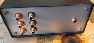
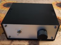
I'm fixing my fathers Akai CS-F21 cassette player.
Last time it has been used as cassette player was around 2008, later I was using it as headphone preamp I would say it was around 2014 to 2016.
After that it was stored at room temperatures.

I had changed the belts, cleaned heads and other moving parts.
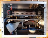
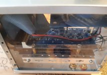
I can't see any obvious problems, caps look good, no oxidation, ...

It can play and record well, I'm using cro2 tapes and man it sounds nice.

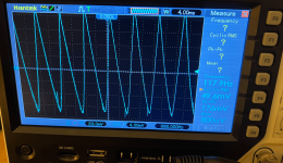
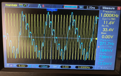
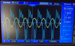
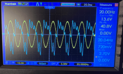
Problem is that after about 30 minutes of playback music gets cut out by a loud buzz. If I stop and when I hit play I can hear the music for a split second. Buzz can be seen on db meters and if I change cassete type (cro2, normal metal), buzz also changes, buzz does not change when I move dolby switch and volume can still be controlled with output level switch.
Buzz is not there if I use it as preamp (REC PAUSE), but I had not tryed to actually record while problem is there.

I don't know much about cassette players and what stages it has (got to do some reading on that) , but my diagnose is that problems is somewhere between the tape head and it's preamp, but before dolby or output preamp.
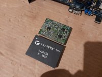
My plan is to take the pcb out and inspect for bad solder joints and if I cant find anything obvious I will try to find schematic and do some signal testing with the scope and maybee listening on some test points with headphones / small speaker.

My question is:
Can tape head go bad and cause a problem only once it warms up?

Did anyone had a problem like that and fixed it?


Here is the video of the buzz:
Video

Thank you

I need to replace my mega XLS10 tapped horn - help! (HT)

Hi everyone,

I'm currently enjoying a single XLS10 in a mega tapped horn enclosure that a friend designed for me. Unravelled, the waveguide is about 4 metres long! It's powered by a Hipex PSC2.400 with DSP.

This supports the rest of my HT setup, comprising of a Yamaha RX3050 AVR and a 9 channel Atmos configuration using DLS speakers (for 5.1.4 in total).

So now, the point. The current sub enclosure sits happily in one corner of the room and due to future renovation plans, there will no longer be room for it in its current incarnation. So I need to come up with an alternative solution.

We're looking to build a 'media wall', with a storage bench going all the way along the wall (approx 5m wide). This will have a selection of cupboards and drawers to house AV equipment, media discs, etc.

So obviously I'm looking at the possibility of integrating a subwoofer(s) within this new furniture. I don't want to go to the hassle of trying to re-work the tapped horn design into it, so really I'm looking at sealed or possibly ported enclosures.

Now I've read a few threads on here about people's experiences with XLS10s, I'm familiar with the passive radiator concept, and also the port requirements for the driver (which may not be an issue with the amount of space I may have in the overall cabinet).

I do have two spare brand XLS10 drivers that I would love to use, so I'm opening this design challenge to the experts on here to see what's possible!

I've attached a few photos showing the current space, a cat investigating sub bass, and a basis wall example (mine won't have a fake fireplace).

Look forward to your thoughts!

Attachments

  • 1-LOGO2.png
    1-LOGO2.png
    1 MB · Views: 160
  • Screenshot_20221007_115203.jpg
    Screenshot_20221007_115203.jpg
    157.8 KB · Views: 152
  • Screenshot_20221007_115116.jpg
    Screenshot_20221007_115116.jpg
    332.3 KB · Views: 146

Design Comments

I would like some technical comments on my design. That is, not whether it is beautiful or ugly.

Since the cabinet is cylindrical, the bass will penetrate much deeper into the cabinet than the tweeter.
I have tried to take this into account by making a slope at the top of the cabinet (12 degrees).
The Tweeter thus comes further back, so that bass and tweeter are now almost in line as if they were placed in a flat baffle.
They are therefore not in the acoustic center, so the slope should be greater or the tweeter should be recessed deeper
into the cabinet and there should then be a waveguide in the cabinet. But is it a problem that the treble plays up a bit
when the bass plays straight ahead. Wilson for example uses almost the opposite principle so that all drivers point directly to it
towards the listener.

Inside, there should be very little opportunity for standing waves. There are 12 edges that are offset from each other
and the front goes very deep into the cabinet, and is very uneven, so there are no large flat surfaces facing each other.

The bass reflex comes out through the base, so the base is part of the speaker.

Attachments

  • Spike.jpg
    Spike.jpg
    282.1 KB · Views: 181
  • Like
Reactions: vineethkumar01

Improve PSRR of LTP w/ emitter current source

Hi there, i have no clues about PSRR to start about, i was trying some caps here and there but it didnt help. What i do to see PSRR in spice is in spite of putting a DC source (48v) i put a sine source with the same dc offset and something like 50mv 30Khz singnal. The LTP seems to amplify the noise in the same way it amplifies signal, and we are talking about 58dB in sim. I think it could be even more with some matched bc560c, or other higher hfe device. The general idea is to make a mic preamp that can give u +4dBu from mic in as minimalist as posible. At the momment i got about +15dBu from a 10mv signal and about -10dBv from a 1mv signal. So i could simply add an attenuator not to clip power amp if the mic is too sensitive, but the PSRR is awfull! Any thoughts?

1666145411590.png

Attachments

  • 1666145386841.png
    1666145386841.png
    6.1 KB · Views: 115

Amp 5 channels and 2 transformers

Not exactly a DIY question, but I guess this is the best place to ask. I have seen 2 channel amp with a single transformer and the single transformer feeds the two channels, Dual mono amps where each channel has its own transformer, but how about a 5 channel amp with two transformers? How is the fifth channel powered? Can the two transformer power the fifth channel or one transformer powers 2 channels and the other powers 3 channels or the two transformers power is pooled into a single source and powers all 5 channels?

B2 Spice and the 723 regulator

I've been trying to develop a precision voltage reference for HV power supplies and I'm using B2 Spice for simulations and I found it's pretty darn accurate. I have pictured below a curcuit I simulated, which is the voltage reference amp contained in the UA723 regulator,and it matches real world results very good! I used general purpose BJTs and a J111 for the ccs, and the Vref and Noise output is spot on. which is 7.25VDC and a noise output of 2.5uV. the HV Vref curcuit I put togther has a lower noise figure of 150nV, which I was surprised!

Attachments

  • 2B364F56-E10E-4483-AACF-A4489543537A.png
    2B364F56-E10E-4483-AACF-A4489543537A.png
    59.7 KB · Views: 145
  • Like
Reactions: Johno

Various Drivers For Sale

CDT HD-6 About fifty hours use, some of the black finish came off the front of one basket when I removed the Fast Rings.

Wacecor TW030WA04 Tweeters Over Two Years Of Use In My Car. One Has Low Output, One Works Fine.

JBL MS-52 set, very low hours use. One of the tweeters has low output and only 1 tweeter grill, otherrwise perfect working order.

SB Acoustics SB65WBAC25-4 Less Than One Hour Of Use.

Wavecor FR090WA02 Fullrange Less Than 1 Hour Of Use.

Wavecor FR070WA03 Fullrange About fifty Hours Of Use. One has a small dent in the dust cap and one has a small dent near the surround.

Wavecor TW022WA04 Tweeters About fifty Hours Of Use.

Wavecor TW022WA02 Tweeters About Two Hours Of Use.

$250. Plus Shipping

Attachments

  • SPEAKERS FOR SALe.jpg
    SPEAKERS FOR SALe.jpg
    780 KB · Views: 118

Krell KRS-2 with KRSP-2 power supply. External transformer needed..

Just got from an auction this beautiful Krell KRS-2 with KRSP-2 power supply. BUT the external box with the transformer is missing.
From what I see in the first pic: 4 transformers for 2 voltages and 2 channels.
Should be not difficult to build a box with these.

Question: Does somebody know about the needed transform secondary voltages / ratings?

PS: The cable from the KRSP-2 to the KRS-2 with the Lemo connector I do have.

Thanks
GM

Attachments

  • krell_krs_power_supply_intern.jpg
    krell_krs_power_supply_intern.jpg
    268.3 KB · Views: 108
  • krell_krs-2_inside.jpg
    krell_krs-2_inside.jpg
    392.4 KB · Views: 128
  • krs-2_backside.jpg
    krs-2_backside.jpg
    197.2 KB · Views: 109

how to unmute or reset DVD player directly without remote control?

i forgot to hide the remote control of dvd player that already broken (plus volume and some button not work) when my friend and his son visit me last week. his son press minus volume until the sound is gone, so because of that, my dvd player can't sound. i try find remote control on online shop with same to this but not find it. finally find general remote then i bought it. unfortunetely that remote doesn't work after i input every 3 digit (trial and error).
is there any way to reset the dvd player direct at the dvd player so the sound coming again?

ICEPower 500ASP + 500A or 2x 500ASP?

I bought an ICE 500ASP and paired it with a 500A module for a 2 channel amplifier a couple of years ago. I've been reading recently that even though they are meant to work together, its more recommended to use 2x 500ASP modules instead. I know the 1000A is bandwidth limited, as opposed to the 500A. I've seen the charts in the datasheets and they seem to have some minor differences, but is it worth it?

Looking for FaitalPRO 12PR320 8Ω FRD and ZMA files

Hi all, first post on this forum so apologies if I'm in the wrong place. I'm looking for 0deg and 30deg FRD files for

FaitalPRO 12PR320 8Ω and FaitalPRO 12PR330 8Ω​

along with the associated ZMA file. Does anyone know where to find these? I've looked everywhere but I don't have the tools (or drivers) to measure these for myself.

If these aren't available, is it possible or stupid to use VituixCAD with a roughly similar driver to at least get a rough idea of the initial crossover which could be modified once the speaker is built?

For context, I'm building a ~95dB 3 way PA with ~50L enclosure using this as the mid-bass, B&C 5MND38 8ohm as mid and Monacor DT300 8ohm as tweeter.

Any help would be massively appreciated!

For Sale Rohde & Schwarz UPL B4 B29 B22 B23 Audio Analyzer

Hello.

I have for sell well known audio analyzer Rohde & Schwarz UPL 1078.2008K06

It has installed options: B4 B29 B22 B23

Analyzer have some scratches on the case, but front panel is in very good condition. No feet, it was working in rack. no other accessories, only EU power cord.
Fan's in good conditions, they not very loud.

Price: SOLD + shipping
Shipping almost worldwide.

20221004_161146.jpg20221004_161153.jpg20221004_161200.jpg20221004_161251.jpg20221004_161307.jpg20221004_161342.jpg20221004_161502.jpg20221004_161507.jpg20221004_161516.jpg20221004_161519.jpg20221004_161909.jpg20221004_161930.jpg20221004_162019.jpg20221004_162032.jpg20221004_163617.jpg20221004_163650.jpg20221004_164254.jpg

MacAudio z4100 not working

Hi there!
I'm new here so I hope I'm posting this in the right place. I have a MacAudio Car audio amplifier z4100 which I'm trying to fix.

It seams I have high voltage coming from Protect signal to TL494 IC controller , turning the overload red led ON. There isn't audio at any of the outputs.

There are some set of transistors (C5198 & A1941 pairs) getting extremelly hot together with their 5W ceramic resistance. (mainly Channel 3 and 4)

I uploaded some Schematics thet I found of z4200 model which is quite similar. The marks in red were not done by me. So, it doesn't refer to my problem.

Any help will be appreciated!

Thanks!

Attachments

  • 1773618100_1300813065.jpg
    1773618100_1300813065.jpg
    127.8 KB · Views: 105
  • 3633528300_1300811089.jpg
    3633528300_1300811089.jpg
    165 KB · Views: 123

Can i build Phonostage with AD1 DHT like this?

I'm planning to make a Phonostage with a Triode tube with an existing Hashimoto Transformer. This schematic is just a draft, with a Tamura TKS22 input with an Indirect Heather triode REN904 ( 20 - 30Mu) - Hashimoto Hl 20k (OTL) and Hashimoto EQL ( RIAA) amplifier and an AD1 DHT as preamp.
Can it run well? any suggestion? Thank You.

Attachments

  • phono DHT2.JPG
    phono DHT2.JPG
    68.4 KB · Views: 261
  • 20221018_124651.jpg
    20221018_124651.jpg
    530.3 KB · Views: 235

Current Drive for Headphones & The Super Linear Transconductance Amplifier

As probably the last circuit we shall build for headphone amplifiers, we want to find out how they sound under current drive.
This is not only known for loudspeakers, but also for headphones, especially for planar magnetics.

The circuit is an evolution from our earlier Pioneer Super Linear Headphone Amplifier.
https://www.diyaudio.com/forums/headphone-systems/313163-pioneer-super-linear-circuit.html
Only now it has been modified to output current instead of voltage.
Many of the aspects of the SL Voltage such as device matching, etc. still applies.

You can read about the article here :
http://xen-audio.com/documents/cdha/Current Drive for Headphones Public 181006.pdf


Happy reading,
Patrick

.

Attachments

  • 180715 SL Trans Top.jpg
    180715 SL Trans Top.jpg
    111.8 KB · Views: 3,415

ADCOM GFA-5802 Thermal LED

Was listening to my amp and suddenly heard a hum and my left channel thermal LED is on and no sound from that channel. Right channel is functional. When powering off the system or unplug the AC connector, the LED goes off.
Already checked T40 (85-degree Thermal Breaker) and it is ok (compared left and right channel and they both are short in normal room temperature).
Any idea what else could cause the thermal LED to stay on (Thermal protection always activated)?

Sony TA-4650 Oscillating

Hi, I've been refreshing this amplifier over the past year in stages. First the PS then on to the amplifier board. I replace all the the electrolytic caps first and it was so far so good. Listened to it for a few months then decided replace the non-electrolytic caps. The outputs transistors are good but the amp is now oscillating. Being somewhat frustrated now I decided to bring into an audio service center in Chicago that is an authorized repair some very high-end gear and is very familiar with V-fets. Anyway, they believe the problem is with the ceramic caps that I replaced with poly-caps in the feedback circuit that is causing the oscillation. Everything else checked out fine on the amp. So my question is it possible the the makeup of the cap is critical here? Ceramic vs Poly? I don't post much here but I would appreciate some feedback on my situation. Thanks!

CCS and voltage references

I've being working with constant current sources in designing a voltage reference for valve based power supplies, and I started out using a single MOSFET(DN2540- TO-92). Im only using TO-92 packages to save board space, because this will be a plug in module for the power supply.

Below I have an example of what I have arrived at. the VR stablizer is also variable. I would welcome any opinions from those that have worked with current sources. All active BJTs are MPAS42 divices. With this CCS Im able to deliver 2X the amount of current to the zener and temp comp diode.

Attachments

  • B9AB1D59-D251-4C4E-93E0-0DD9026E181E.jpeg
    B9AB1D59-D251-4C4E-93E0-0DD9026E181E.jpeg
    334.7 KB · Views: 233

Quadral Aurum 9 sad story short

Hallo to audio lovers. Past few days i decided to sell my 30years old Infinityes as im tired of watching them and buy something old/new for me.So Aurums by Quadrals caugth my eye so i went for it. The have beautyful design and good choice of speakers inside wich are 2x8"woofers, 2x5" midds and on top RIBBON TWEETER..mmm nice. Wood finish is exelent !! So i buy them and brought them home..After few minutes i notice that is not much clearance in sound and everything is muddy sounding!? W*F.. i just buy.. Im schoked. Soo after good nite rest i started testing and speakers are all ok. Woofers and bass port are in faze, midds are allso good placed and tweeters 100% okay, so only thing i could think of was FILTERS !! So i open the speakers to find out "##€"#€##"€€€."!"";+€-*:#;€.. What in gods name was Quadral thinking?? See picture as i cant talk now.. I must stop..Sorry

Attachments

  • IMG_20221016_192928.jpg
    IMG_20221016_192928.jpg
    669.4 KB · Views: 209

Sub for Electrostats

I am currently using the Gradient SW63 with the Quad ESL. The woofers are tired and the XO unit is getting noisy. I began looking at re-driver'ing the Gradient but then started considering other possibilities. Surely in the past 30 years there are better approaches that I can put four new drivers into.

The Gradient kept up well with the Quad. I have another set of subs, the Dayton RSS315, which put out plenty, but just don't sync with the speed of the Quad. And they start to drop fast after 40Hz.

I like the concept of the dipole and have been looking at a number of H, W, Z, V etc. configurations. The Linkwitz design for his LX521 seems to have some interesting advantages but I'd really prefer to avoid the active equalization.

In the end, I'm open to whatever the best solution is- I'm not married to any particular approach.

Thanks in advance for the suggestions and guidance.

Three way horn system

Three way horn system (4 way at the moment)

Hello all. After some time of lurking, this is my first post. Recently I have heard my friends horn system. As mid-bass he uses w-bin folded horns with one 12" Isophon driver, roughly 100x100x80 cm in size, then something like "smith" radial horn with a Coral 1" driver and Coral tweeters at the top, all with active crossovers. Except for PA, my first experience with horns.

What I noticed, the bass guitar, snare, kick, voices - all almost like alive during a rehearsal (I am musician too). I could even feel the bass, although it could not be very low. The music was playing loud, but it did not feel lound until i tried to speak. Awesome. I have a few questions.

What would be the bass-mid crossover frequency for such a system?
I hope I could use compression drivers and horns from around 1kHz, but I am afraid bass horns just won't fit into my room. What bass system would you recommend? I do not need very low frequencies, I would like to have this tight sounding bass. As far as drivers concerns, I am more or less limited to Monacor, Eminence, B&C, Selenium, Beyma or RCF.

Update after 11 years🙂 (BTW, the horn system described above was identified meanwhile as the Danish Jealvox clone)

The current setup (October 17th, 2019) is (per side):
40 Hz bass horn with 15" speaker - Cerwin Vega inspired design - up to 120 Hz (one more per side is waiting to be installed)
JBL4560-like front horn with 15" Black Widow speaker - up to 600 Hz (to be replaced with John Inlow 135 Hz midbass horn in a few months)
JBL2445 + JBL2380A clone - up to 4.5 k, passive XO to HF (gorgeous Yuichi 290 horns are in production)
Beyma CP385Nd on 2380A with a custom 3D printed adapter (will be installed soon - the prototype needs some little adjustments)

The HF + MF will most probably be one day with a single 1.4" driver (maybe BMS4554) either on the Yuichi or another large horn.

Each side is using 3 channels of amplification (SE EL34 for the MF+HF) and one t.racks DSPmini for crossover, delays and EQ.

Help With Tube/Mosfet Amplifier.

Can someone Help me with this, I use EasyEda to build this. But it does not work, and I don't know why can someone tell me where is my mistake?

I can't bias the amp. The bias point jump from 0.4V to 8-12V and the Tube Become a more like a light bulb, There is no sound, The antipop relay delay circuit that is there is for DC protection, it works fine, it is switching as it should.


12AU7-IRF510-Headphone-Amp-Schematic.png


Schematic_Tube Mosfet Amp_2022-09-21-1.jpg


PCB_PCB_Tube Mosfet Amp_2022-09-21-1.jpg

I've been shopping NOS Peerless drivers

I'm a sucker for a bargain
These are both NOS and selling on eBay locally
The KA20 DMR and an interesting oval mid-range driver with a separate sealed can back.
Has anybody here done any work with the 50mm dome mid?
Running the test on the unit is seems to measure similarly to the old model Jaycar/Dayton dome.
I didn't expect much for my $10- so I am not really disappointed in the oval driver. Party box mids if I double up for power handling. Sealed box Fb is 300 and not much different to the domes really Louder tho and evident breakup although I was driving them full range

Subwoofer Enclosure

I’m going a different route on my sub woofer enclosure and building a new one .

I know they say use wood glue and clamps and there is no need for screws .

Personally I feel better using screws along with wood glue or staples brad nails . Since there is gonna be high pressure levels inside the vehicle.

Wondering will brad nails or staples works just as good as screws would ?

What’s everyone’s thoughts on this since this box is going into a SPL vehicle.

Hantek 6022BE Digital Oscilloscope

Hello all, I went into my local electronics shop to look for a scope for working with audio analog circuits

I was recommended this with the advice that this unit can do frequency response
https://www.jaycar.com.au/20mhz-usb-oscilloscope/p/QC1929
https://www.jaycar.com.au/medias/sys_master/images/images/9704167899166/QC1929-manualMain.pdf

Then I came across this
http://hantek.com/products/detail/31

Are they the same unit?
Can I use the Hantek 6022BE for analog audio circuits?

Also
What are the crowd favourites when it comes to speaker parameters? Can unknown speakers be worked on to generate the parameters somehow? What's needed for measuring built speaker response and such?

Is there one device that I can use for both circuits and speakers?

Thanks and regards
Randy

For Sale Clone Note LDR volume control

Hello,
I've converted all my system to digital, so I've for sale a Clone Note volume control from the original kit in perfect working order. All the RCA connecotors are Neutrik
150 euro + shipping and Paypal fees.
Shipping from Italy.
Best regards
Guglielmo

Attachments

  • 20220924_114911.jpg
    20220924_114911.jpg
    254.3 KB · Views: 234
  • 20220924_114933.jpg
    20220924_114933.jpg
    468.5 KB · Views: 232
  • 20220924_121305.jpg
    20220924_121305.jpg
    515.8 KB · Views: 229
  • 20220925_124758.jpg
    20220925_124758.jpg
    203.2 KB · Views: 222

Replacing Driver/output transitor combo with single darlington?

I have laying some nice schematics where power section is triple darlington style output stage (which is formed using 2SC3221>2SC4883>2SC2922 , but I have a bunch of 2SD2561 Sankens with I like to use for the last two stages. picture explains it all.

apart ability to acess inner base to add 10ohm (together with no ability to disconect that internal 70ohm resistor) what are drawbacks of this circuits? any bias issues and sonic penalties?
thanks a million

Attachments

  • sanken.png
    sanken.png
    12.4 KB · Views: 151

Could solar-powered headphones be the next must-have?

https://www.bbc.com/news/business-63211086
Could solar-powered headphones be the next must-have?
By Nick Dauk and Will Smale
If you are the type of person who is forever forgetting to charge your wireless headphones, help may finally be on hand.
It comes as the first commercially available solar-powered headphones are now on sale. The models, by Swedish firm Urbanista and German sports giant Adidas, both have solar panels built into their headbands.
In each case the flexible panels are made by another Swedish company, Exeger, which has spent the past decade working to make them light, thin and powerful enough to do the job.
  • Like
Reactions: dreamth

Floating Tangential Tonearm

Hi! Greetings to all from a new member.

Some links related to my DIY turntable - TTT - utilizing a floating tangential tonearm after the idea/license of Nikolay Ivanov.

The TTT Vernissage clip:
YouTube

The first TTT development report:
YouTube

The "TTT Vernissage" series, all recordings made with TTT:
YouTube

I will be very glad to discuss with you on any issue related to my construction.

Tripath TA0103A repair attempt

Hello guys

I have had over 5 amps lately for a repair based on the Tripath TA0103A chip, Impulse SD-1200, Phoenix Gold Tantrum 1200.1, Phase Linear Opus 1, US Amps and etc.

Same board same stuff, pictures in the link:
https://amp-performance.de/en/1222-Phase-Linear-Opus-1.html

All of them with a defective output section, some had output mosfets blow up, others only the chip was defective.
I've tried to order TA0103A from 2 different sources from China the chip, but sadly no avail, they were either fakes or blown up

Decided to open up one of the chip....i've found a few blown up transistors. Will try to read the markings and replace them. I know if the ics, big black blobs, are gone it's game over.
But as I have 5 of them just laying around with no other options, i don't have much to loose.

The only issue is that i don't know the values of the capacitors... I highly doubt there is a schematic for the Tripath TA0103A. I've read all of the threads over here about Tripath TA0103A.

Has anyone ever tried to repair one of those ? Any advice ?

Attachments

  • 1.jpg
    1.jpg
    404.7 KB · Views: 261

Up Squared I2S Audio

Hi! This is Jose Miguel.
I want to build my new hqplayer naa endpoint v3 based on Up Squared (Pentium N4200 - UP Squared specifications – UP Bridge the Gap). It is a very interesting device not only because its small size and quite powerful features, but also because of its I2S audio output directly from SoC (Apollo Lake) via de 40-pin GPIO, similar to RPI.
My idea is to take this I2S output into a top quality I2S reclocker (Andrea Mori, etc.) using the best clocks available (new Driscolls Andrea Mori as well) and then route the output to my DAC. This setup would make the USB conversion unnecessary. The ugly side is that everything above is still at development and support is not the best.
Currently it should be possible to connect via I2S the Hifiberry DAC+ Std. to UP2 adding the SOF driver support to PCM512x ( Set up SOF on Up Squared board with Hifiberry DAC+ (STD) — SOF Project 0.1 documentation ).
If this works, it would be possible to connect to the I2S pins at the hiffiberry to any othe I2S input device (the reclocker in my case). I assume that some audio device should appear in the ALSA aplay -l (Ubuntu 18.04.5).
In the same SOF project there is also support for WM8804 (same link above) so some digital interface (Hifiberry DIGI+, Twisted Pear,Audio??) based on this Wolfson IC should be compatible.
It would be great to know what do you guys think about this setup, and get some feeback in case someone has already tested.

Integrated power amplifier build

I'm building an integrated power amplifier. This will be based on the Trimodal power amplifier and the Precision pre-amplifier by Douglas Self. I really liked the books Douglas wrote and I decided to build this integrated amplifier. It will use to power amplifier modules based on the trimodal amplifier with four output transistors (2xNPN + 2xPNP), the updated Precision pre-amplifier with 5K linear pots and LM4562 or LME49720 opamps. I will also build the phono pre-amp with teh same opamps. The power supply will be a combination of unregulated (for the power modules) and regulated with LM317/337 for the pre-amp. So far I managed to solder the power amplifiers and I performed some measurements in class A and class B (D. Self class B 🙂 ). The results can be seen in the images below. The THD at 1kHz and 8OHM load looks very good. This is close to the limit of the Quant Asylum QA401 analyzer. Due to the size of teh heatsinks, the power amplifier will have a quiscent current of 1A. The original design by D. Self has a quiescent current of 1.6A. With 1A it can deliver around 12.5W in 8OHM. This is quite enough for my needs. In class B the quiescent current is around 50mA and the THD is also very good in my opinion. It does have a significant 2nd order distortion that I will have to look into. But for now this will have to do. I'm focusing on the other boards. I will add updates regarding the build as I go.

Power_AMP_Class_A_1A_bias_8OHM.png


Power_AMP_Class_B_8OHM.png

Newby question: What's this capacitor for on a DC mA meter?

I picked up some nice analog Simpson mA panel meters from a swap meet so I can direct-wire them into breadboarding circuits without using a sense resistor and get the immediate response of an analog meter. Some of these meters had a .01 uF capacitor across the pins as seen in the photo. Now it's my understanding that the ideal voltmeter has infinite impedance and hooked up in parallel. And that the ideal ammeter has zero impedance and is hooked up in series. If an analog DC ammeter is to be hooked up in series why would someone have installed this capacitor? The meter is pretty accurate, I tested it against my Fluke, I want to use these to make things more visible while breadboarding and trying stuff out. Should I install a .01 capacitor across all of them? He sold me 1mA with centered needle. and full scale 5ma, 25ma, 50ma, 100ma and 150ma meters. See photo below. Just confused why the capacitor is installed.

PXL_20221015_202411039.jpg
PXL_20221015_202426686.jpg

FOR SALE: EML 50 tube (pair) (satisfaction guaranteed) Less than 25 hours

Asking $500, New $750
LIKE NEW (< 25 hours)
EML 50
Only owner
5 day money back guarantee (less shipping)
Just want to find a happy home for these MINT condition tubes

Attachments

  • IMG_0515.JPG
    IMG_0515.JPG
    554 KB · Views: 172
  • IMG_0513.JPG
    IMG_0513.JPG
    442 KB · Views: 169
  • IMG_0512.JPG
    IMG_0512.JPG
    451.1 KB · Views: 153
  • IMG_0514.JPG
    IMG_0514.JPG
    434.6 KB · Views: 159

Transconductance Amp on Electrostatic Speakers...

Hello all!
Just converted a LM3886 amp to a Current Drive - Transconductance amp...Seems to be fine on my B&W DM220 (test speakers), and thinking of trying them on a set of Quads... anyone with any advice? I read that transconductance amps are better geared to Full Range speakers with some amount of Equalization... and maybe not so happy driving high Capacitance - reactive loads

Measuring Class D BTL/PBTL Amps

I have a number of Class D amps with BTL and PBTL configurations and want to use my Digital scope to do measurement. A connects balanced probe is very expensive so I was thinking of using a transformer to isolate the amp from the ‘scope.

Has anyone else done this and if not, can anyone see a reason why this would not work?

The transformer is taken from a high quality 100V line amp, designed to offer a 4 ohm load to the amp and feed either a 100 or 70v line system. It is rated at 240 watts although Judging by the size, that seems conservative.

What can I do with a one way 2,5" Ciare driver? High QTS/low xmax

Hello! While I was cleaning my garage I found a pair of Ciare PA065 which I bought a long time ago. I never used those drivers and I would like to make a pair of good speakers for my room. So far I've had some ideas, I have some doubts about the pros and cons of each solution.

Idea 1)
These seem like the perfect kind of drivers to use for a FAST, but I don't have any other driver to complement it. I could get a pair of TB W46-1316SM (yes they're 4"x6") woofers which are cheap here, small and with plenty of Xmax. Really the only downside should be the cost, which would consist in a pair of woofers and a passive crossover network.
Would be fun to design a waveguide for it, but I've never done such thing and I don't know if there is any commercial waveguide that fits that size of speaker.
Or, I could experiment and use the Ciare as a dipole tweeter.
Could also still try to add the magnet on the back in order to gain a bit of SPL.

Idea 2)
A quick glance at the parameters shows a very high Qts mated with a high Fs (154Hz) and low Xmax (1mm). This makes the speaker not very good in a sealed box because of a very reduced bass extension and power handling, and terrible in bass reflex because of a crazy high Qts. I could glue a magnet on the back of the speaker but I doubt I could get the Qts under ~0,8. But what if I purposedly built a strongly resonant BR enclosure and then EQd it down using a first order high pass? I would get both the high efficency of the BR and I could really limit the excursion thanks to the HP filter. The box would be quite big especially for such a small speaker, but how could it sound?
I won't be able to use a passive HP, so I would probably have to make the speakers active and make an active HP using opamps. I could use a TDA7292 board which are really cheap. I don't think I will be able to use a PLLXO unless I stick to a known source, like a bluetooth receiver. I could adjust BSC by playing with the HP frequency.

This is in a 10 liters enclosure, tuned to 100Hz and highpassed with a 1st order @ 300Hz
Schermata del 2022-09-16 00-37-53.png
This is with without any filters whatsover. There are over 10dB of ripple at Fb.
Schermata del 2022-09-16 00-37-42.png

Idea 3)
Just make a 2.1 with it. Satellites could be either OB or sealed. That would be a very boring approach which I've seen too many times.

Dual mono BrianGT LM3886 problem.

Hi I had this amp working for years but recently one of the channels is substantially subdued.
I tried Servisol 10, twisting volume control and selector switch repeatedly but to no avail.
I can't even find out where to test for voltages to see where the problem lies-the channel isn't completely dead, just substantially muted.
Any help will be very welcome.

+/- power supply for power amp

Hi
I'm building a power amp using the carcass/PS of one that died. I'm using Symasym5-3 kits that want +/- 20-45 DC power (schematic attached).
The PS of the carcass has DC 75 x 2 and I'm planning to use one for each channel.
However, the 75 DCV supplies are not referenced to ground - there is one cap between +/- from the rectifiers (and not two that are grounded at the connection between the two caps).
The DC voltage is within the acceptable range for the amp modules (ie +/- 37V if the voltage is notionally halved) but the +/- would effectively be referenced to ground through the amp circuit.
Is someone able to tell me whether this would be a problem? Or do I need to get new PS caps so I can incorporate a ground reference between two for each supply?
Thanks, Jon

Attachments

  • Screen Shot 2022-10-16 at 2.40.57 pm.png
    Screen Shot 2022-10-16 at 2.40.57 pm.png
    153.9 KB · Views: 531

WinISD, Reliable subs?

Hello all
Running into something that I don't understand

Driver A - 600wrms 8" 18.8mm xmax
Driver B - 200wrms 8" 13.5mm xmax

Test box 18L 34Hz external port

graph.JPG


excursion.JPG


500w signal. Upper trace is driver A and lower is driver B. I don't know how to read this excursion plot. I was expecting driver B to be flapping like crazy with that much power, but it seems comfortable

Is WinISD nuts?

Attachments

  • graph.JPG
    graph.JPG
    107.4 KB · Views: 97

Linn Kremlin rebuild

I've got one of these where the not so "Brilliant" power supply has crapped its pants and from what I have read they're none too reliable at the best of times.
I have discovered that from the factory, they either came with a Brilliant supply (SMPS) or a toroidal transformer.
In a quest to get this unit back up and running I have decided to fit a toroidal as it will be more reliable than the not so Brilliant supply.
Linn have helpfully added instructions on the screenprinting to show which parts should be fitted when the transformer is used, which tracks should be cut etc.
However, there are some parts which are supposed to be fitted but they don't have any type numbers - just the generic 'U507' (a regulator, which I suspect is likely to be an LM317), D514, C526, Z515 etc.
I did contact Linn to see if they could supply me with the relevant info, the specific part numbers and values etc and they said as the unit was made end of line some 12 years ago they have no information.
What would be really helpful is if someone who has one of these tuners could take the top off and determine the values/type numbers of various components, these being:
D514, D516 (probably just 1N4001)
C524, C525
C526
C527
R528
Z515
U507

Attachments

  • Linn1.jpg
    Linn1.jpg
    359.9 KB · Views: 140
  • Linn2.jpg
    Linn2.jpg
    377.6 KB · Views: 121

How to wire Alps pot to Alpha 3 position rotary switch

Newbie here, hope this is the right place to post my question. How do I wire a Alps RK27 10K potentiometer to a Alpha 4 pole 12 throw 3 position rotary switch. I want to wire two stereo input sources with one stereo output. Typical unbalanced RCA plugs to make passive preamp. Diagrams, schematics and pictures are very helpful and appreciated.

Thanks in advance.

Hello from Pennsylvania

Hello all,

From Western Pennsylvania and just found this site / forum today.

Looking to gain knowledge on many audio setups / modifications you can do.

Particularly looking to find out ways to (if possible) use the laser setup on older CD-ROMs to repair some CD Changers I have. Also looking to find out how to identify DACs and how to replace them in a CD Player.

Looking forward to learning. Thanks!
Projects by fanatics, for fanatics
Get answers and advice for everyone wanting to learn the art of audio.
Join the Community
507,782
Members
7,888,242
Messages

Filter

Forum Statistics

Threads
406,228
Messages
7,888,242
Members
507,782
Latest member
stanyoung