Improperly designed power amp units where output power transistors with 30-60MHz are in use as mentioned in post #1 under
https://www.diyaudio.com/community/...amilies-for-audio-power-output-stages.147656/
may degenerate into an RF oscillator - unfortunately often only temporarily (removing or moving of only a single cinch-wire or mains power cord or move the amp device of any few cm lets abruptly break off the unwanted oscillation).
Main reason therefore is a bad layout choice of the conductor tracks - consequence is, that several parasitic capacities are additional present.
Most audio engineers still believe that with regard to human hearing from 20Hz to 20KHz, the design of audio power amplifiers is completely uncritical (compared to power amplifiers for RF/HF applications) and checking the frequency response of audio power amplifiers up to 100 MHz is complete nonsense from the view of those engineers.
I don't think so.
I claim, an examination of those frequency area below and a bit above ft of power output transistors is definitely necessary - i. e. between 0,5 MHz and 100MHz, if ft from power Transistor is 60MHz.
Which is well very far away of 20 KHz.
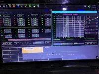
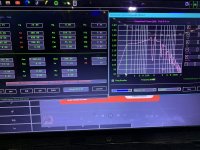
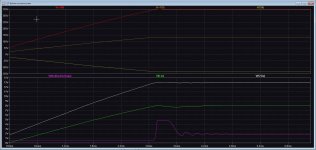
Only then can one clearly see whether there is a tendency to oscillate or not. If there is a tendency to oscillate, the plot looks basically like those from the attached image (red curve) - but the peak is mostly between 1MHz and 10MHz.
If there is full level RF oscillation or if there is an undesired oscillator function immediately (recognizable by the immediate destroy of the output power transistors due occur of max quiescent current value that be supplied by the power supply), this can only be proven with a power supply with integrated current limiting unit (one suspects at first glance faulty pot in the vbe multiplier stage - go to post 14 under
https://www.diyaudio.com/community/threads/differences-between-various-vbe-multipliers.117047/)
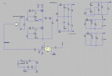
With any few amplifier models that I had on my desk because oscillation issues, I was able to find out the reason with help of the CAD program CIRCUITMAKER. These were the amp models I remember well:
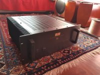
1) Meracus Onesta Integrated Amplifier
http://ftbw.de/xp/amplifier-xp/meracus-onesta-v1.html
The device oscillated sporadically to around 3 MHz with nearly full voltage swing (without speakers and 1K load) also depending on the routing of external connecting like cinch cables) - accompanied by rapid heating of the output transistors BD911/912 (three pairs in parallel mode).
My repair was supposed to be the fourth attempt - this amplifier device had actually been abandoned from the owner.
In the simulation of this circuit topology the frequency response looked smooth up to around 400KHz and dropped off at around 6db/oct. without anomalies up to 100 MHz
Parasitic capacities due to conductor tracks running in parallel were initially not taken into account while first circuit design from the this German manufacturer. As is well known, a capacitance between the output and the inverting input (in parallel with the NFB resistor) is critical, which was not planned or taken into account while circuit design.
Due to the parallel PCB routing on both component and solder sides, a capacitance of about 70pF was created (noted by measuring after de-solder several resistors and caps around the NFB loop).
After introducing this capacitor into the circuit in the simulation (CAD-program), the oscillation was also present here - slightly deviating in frequency and level in opposite to those from real live (according my own oscillographic measurement).
The frequency response measurement looked basically like the last diagram on the third to last page under
https://hifiakademie.de/pdf/phono.pdf?si=google
however, the peak before the drop was around 2.5-3MHz.
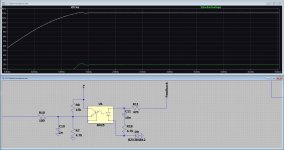
I increased the capacitance in the circuit under simulation to 220pF, which made the peak even more pronounced, and then changed the values of all present compensation capacitors so that a flawless "roll-off" between 1MHz and 100MHz was occur (effortful work and many sessions on my personal computer).
After introduction of new capacitors in the "ONESTA" itself with the values from the simulation and the 150pF capacitor parallel to the NFB resistor (= 220pF ./. 70pF), flawless operating without any RF artefacts resp. ring-ring effects was also recorded in real live, which is still the case until now (about 15-18 years ago).
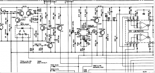
2) Luxman L190
integrated bass-treble control in the NFB loop of power amp section (and passive preamp consisting of source resp. input selector and volume control) - go to
https://elektrotanya.com/luxman_l-190a.pdf/download.html
Perfect function in the middle position of treble control pot - degenerates into an oscillator when the treble control is turned down, the occurred oscillation level being so low that the output stage transistors are not destroyed.
Frequency of ring-ring around 100-200KHz.
Power amp not unity gain stable (same phenomenon as on op amps, not unity gain stable without external compensation). Regardless of whether speakers are connected or not.
The problem was not eliminated because in the currently application the trebles of the loudspeakers used were usually turned up further (full range driver in use without dome tweeter).
3) Philips F4215
https://www.hifiengine.com/man…brary/philips/f4215.shtml
Same observations as on Luxman's L190, but maximum level and destruction of both STK chips.
Correct working amplifier channels without RF oscillation designed with the help of the mentioned CAD program - after doing this no longer RF oscillation even in min-position of treble control pot. Unfortunately I don't have the details anymore. As I remember right, main effort was the creating of a unity gain stable power amp unit.
4) Horch 3.0S
https://www.diyaudio.com/commu...er-output-devices.379808/
Depending on the location, the fuse sometimes but not always blows - even without speakers connected.
Most likely unwanted high level RF oscillation as well. Still has to be tested with a laboratory power supply and current limitation.
In general, it has always bothered me that there are no measurements for home audio amplifier models up to at least 100 MHz and I cannot make any myself to prove whether the peak before the final frequency response drop is missing or not - the latter would always indicate that the phase reserve is too low - see basic description under
https://bilder.buecher.de/zusa…20871/20871854_lese_1.pdf
A low pass filtered square wave form at the amplifier output as seen under
https://www.amplifier.cd/Verstaerker/verstaerker/images/rechteck_10kHz.jpg
and numerous under
http://saba-forum.dl2jas.com/index.php/Thread/8271-square-wave-behavior-of-hi-fi-amplifiers/
is no guarantee that no oscillation or undesired ringing can occur - but a smooth roll-off (i.e. without a preceding peak in the upper range befor falling) in a frequency response measurement up to 100MHz is a clear evidence of this.
To carry out this measurement one need an RF-capable broadband noise generator and the possibility of such a frequency response measurement display. Furthermore, all filter capacitors must be removed outside of the NFB loop - mainly the input capacitor for limiting the slew rate and limiting the upper cut-off frequency - otherwise I get not helpful results and looks like those under
https://www.amplifier.cd/Verst…ages/gain_db_normiert.gif
Does anyone have experience with this kind of measurement on audio amplifiers ?
Which measurement could alternatively (to the frequency response up to 100MHz) to be made to estimate the risk of unwanted RF ring-ring ?
Many thanks for hints.
P.S.: this threads don't provide the appropriate information:
https://www.diyaudio.com/community/threads/amplifier-oscillations.3767/
https://www.diyaudio.com/community/threads/audible-or-noticeable-symptoms-of-oscillation.73724/
https://www.diyaudio.com/community/...il-override-problem-with-my-power-amp.323960/
https://www.diyaudio.com/community/threads/parasitic-oscillations-in-general.137972/
https://www.diyaudio.com/community/threads/rf-suppression-in-power-chip-amps.191989/
https://www.diyaudio.com/community/threads/relaxation-oscillations-in-an-amplifier.361203/
https://www.diyaudio.com/community/threads/amplifier-oscillation-problem.207554/
https://www.diyaudio.com/community/threads/check-for-oscillating-amplifier.162545/
https://www.diyaudio.com/community/threads/oscillation-in-ecl86-amp.338885/
https://www.diyaudio.com/community/threads/amplifier-oscillation.50697/
https://www.diyaudio.com/community/threads/amplifier-oscillation-problem.207554/
https://www.diyaudio.com/community/threads/amp-oscillation.97569/
https://www.diyaudio.com/community/threads/parasitic-oscillation.351771/
https://www.diyaudio.com/community/threads/op-amp-oscillation-advice.358610/
https://www.diyaudio.com/community/threads/neutralizing-an-amplifier.224046/
Maybe under
https://www.diyaudio.com/community/threads/bob-cordells-power-amplifier-book.171159/
or in one of the books under
https://www.diyaudio.com/community/...amplifier-books-overview-google-books.153311/
are some hints concerning the create of frequency response plot of audio amplifiers up to the RF area.