WAW via an external Subwoofer

Hi Guys,

I've been reading about WAWs and want to try to make a single driver speaker where I use my Dynaudio Sub from about 120 Hz and down. Pretty standard.

But what if I want to add a high-pass-filter on the single driver?

Two questions:

- Is there a way to add a high-pass-filter that doesn't compromise the purity of a the single driver? (I really like the idea of practically nothing but speaker wire between the amplification and the driver).

- Is there a way to add a switch where I can toggle the high-pass-filter on and off?

I'm a complete amateur and, admittedly, part of the attraction of a single driver speaker is the simplicity of no crossover.

Best regards
Mads

Korg B1 tube pre amp kit ($125)

I have a korg b1 pre amp kit from diy store. Never got around to finishing the project. Unfortunately need to sell it. Comes mostly completed with components. Comes with everything in the kit but No chasis. Also added upgraded capacitors. As you can see whats been done and for sale in the pics. Also have few xtra components. Im located in so. California. Willing to ship for few buks.also have hakko solder iron and kestor solder available if interested.

Attachments

  • D13B2606-B08D-4693-B5DA-7C4754C194FA.jpeg
    D13B2606-B08D-4693-B5DA-7C4754C194FA.jpeg
    307.5 KB · Views: 144
  • 973BCA93-E0B5-4E2E-82EA-C2CBA5AF4A15.jpeg
    973BCA93-E0B5-4E2E-82EA-C2CBA5AF4A15.jpeg
    371.6 KB · Views: 131
  • 53240BDF-5217-421F-A930-97A55F5D0D8D.jpeg
    53240BDF-5217-421F-A930-97A55F5D0D8D.jpeg
    376.4 KB · Views: 128
  • C77079C9-54B3-48FA-BB09-EEA27FE14FD4.jpeg
    C77079C9-54B3-48FA-BB09-EEA27FE14FD4.jpeg
    418.1 KB · Views: 121
  • BA9B27D7-A155-418D-80C1-430B6BF9536C.jpeg
    BA9B27D7-A155-418D-80C1-430B6BF9536C.jpeg
    398.4 KB · Views: 129
  • E86A6A8F-AD28-4F61-BD04-B570067AB0A1.jpeg
    E86A6A8F-AD28-4F61-BD04-B570067AB0A1.jpeg
    322 KB · Views: 131
  • 6E53F9E7-4D8A-42E1-B3D1-52DC4C7DBBC6.jpeg
    6E53F9E7-4D8A-42E1-B3D1-52DC4C7DBBC6.jpeg
    374.9 KB · Views: 120
  • 2BDE1204-D3CA-4E7D-A27D-ECA7DFAF51CE.jpeg
    2BDE1204-D3CA-4E7D-A27D-ECA7DFAF51CE.jpeg
    410.3 KB · Views: 120
  • FB840418-EC27-463D-9BD7-D0B79743E96B.jpeg
    FB840418-EC27-463D-9BD7-D0B79743E96B.jpeg
    402.6 KB · Views: 123
  • 2E529413-899E-498C-8A57-60245B6C0F9F.jpeg
    2E529413-899E-498C-8A57-60245B6C0F9F.jpeg
    368.4 KB · Views: 123
  • 42289BB8-98BC-49DF-9DAD-2FB9C503CE23.jpeg
    42289BB8-98BC-49DF-9DAD-2FB9C503CE23.jpeg
    328 KB · Views: 139

It took 40 years built I finally did it

In 1980/81 I was studying electronics at Durham, England.
In the morning we did theory and in the afternoons built up circuits to test the theory.
One of the projects was a LM386 amplifier.
There were about 12 of us in the class.
We started building up the pcb and then started testing.
There was a loud crack and a electrolytic capacitor exploded.
Big cheer went up.
About the half the class got the cap the wrong way and exploded it.
Being a smug git I managed not to blow mine up.

After 40 years in electronics I have never blown up an electrolytic cap.
Well until today I finally did it with a 100uf 35v electrolytic.
Obviously not concentrating.
So not so smug now.

Open Baffle Speaker < less $300

My buddy David Kan sent me his wonderful open baffle speaker..


2 pieces of Ikeas Chopping board
12 screws at the top + 6 screws at the bottom
6 pieces of Aluminum Flat from Home depot
1 pair of Visaton 10CM Coxial driver HX-10 or B80

https://www.ikea.com/ca/en/p/aptitl...Mnv_wtK2MUf33y0M88BUxHB-sVKZYg8EaAnecEALw_wcB

I love this wonderful design...
  • Like
Reactions: JamieMcC

Vintage chassis for tube projects, new with accy's

Offered here is a cool new-old-stock chassis perfect for tube projects. This has been sitting on shelf in my basement for at least 25 years if not longer, and are likely much older than that. Steel chassis with black crinkle finish (powdercoat?). Dimensions 5" x 7" x 6.25" H. The lower section is open on the bottom. In the bags are a metal top handle with hardware, and screws for the box halves.

Price is $49 plus shipping from USA zip 87501. Paypal is fine, no added fees.

Two of them are available.

Attachments

  • tubebox1.jpg
    tubebox1.jpg
    378.8 KB · Views: 170
  • tubebox2.jpg
    tubebox2.jpg
    196.2 KB · Views: 173
  • tubebox3.jpg
    tubebox3.jpg
    296.2 KB · Views: 166

DSP Programming help

Hey everyone,

I had purchased an amp+dsp called the "FXtreme DB450" from a user on this site named Prinkiestonkie. I had originally found him on Instagram. I've had the amp for a while and have only recent gotten a chance to make something and utilise it. However, I am a noob when it comes to trying to program the DSP. I've done some basic tuning on my Helix DSP in my car but I can't even get this amp+dsp connected to my PC. The amp was shown off in this forum here but the user has been banned, his website is down, he is not replying to his instagram comments or DMs and all youtube videos have been made private which leaves me in a pickle. Just wondering if anyone can help me get this set up. Here are some of the features:

-8-24v input voltage (4s/16.8v Li-Ion battery or 19v 4a PSU Recommended)
-CSRA64215 Bluetooth 4.2 AptXll <40ms TWS + 8DBi antenna (30m/100ft+ Range)
-ADAU1701 fully configurable DSP (SigmaStudio on PC/Mac required for programming)
-TPA6132 Opamp (Balanced)
-AD8608 Precision Opamp
-LTC1871 Step-Up Booster (Adjustable from 8-24.5v)
-2x TPA3116D2 Amplifier chips (4-8Ohm // 2-4Ohm Mono-Mode)

I can't even find the correct programmer to get this connected to my PC and I don't have a base file to go off for SigmaStudio so any help is appreciated. It would have been great if I could message anyone from the forum post linked above but I can't unfortunately.

Closed box V frame subwoofer

Good morning everyone

Due to space issues and a desire to experiment with something new, I want to venture into building a pair of subwoofers that will form the fourth way of a fully active multi-way speaker. This is a subwoofer that is to operate from 30 to 80 Hz consisting of two 15" PA woofers per side. Most likely 4 rcf lf15x401s that I already own (just a pair for now). I am intent on using them in a closed box even though they don't have the optimum parameters for this kind of enclosure, however working fully active and using a minidsp flex 2x8+ dirac I can afford to linearise the response as I want. I am limited exclusively by the xmax but having a rather small room and being more interested in high dynamics than a rather high constant volume I prefer this type of alignment which allows me to have a smaller enclosure and a more damped response.

The particularity I would like to explore is a kind of v frame baffle. See attached image (taken from another thread on this same site). Obviously unlike this configuration shown in the picture I would like to close the box behind the drivers.

Attachments

  • 29224320-E5EF-445B-B82A-F7AEAE0D9C9F.jpeg
    29224320-E5EF-445B-B82A-F7AEAE0D9C9F.jpeg
    172 KB · Views: 73

Music Angel XD-SE Tube amp

For Sale: Music Angel XD-SE Integrated Push Pull Tube Amplifier. 60wpc in Pentode Mode, 30wpc Triode Mode.
Four newer JJ KT77 tubes, two 12AU7 Phase Splitter tubes and two 12AT7 Driver tubes. Bias all dialed in.

Previous owner completed Lampizator mods. Can audition.

Would rather not ship, but can if buyer pays...

Pickup / Audition in West sub of Chicago.

How's $725 + ship?

Attachments

  • PXL_20221011_000410404.jpg
    PXL_20221011_000410404.jpg
    313.8 KB · Views: 240
  • PXL_20221011_000435879.jpg
    PXL_20221011_000435879.jpg
    338.5 KB · Views: 236
  • PXL_20221011_000439491.jpg
    PXL_20221011_000439491.jpg
    388.4 KB · Views: 243

bang and olufeso cd50

Hello all
I have just got a b&o cd 50 and have now got it working found two faults that were not mentioned any where i could find on line.
1 the main cam wheel and the bottom cam have a locating key and groove so they lock in correct position to each other. I had one from a previous purchase that was beyond saving, and was ok the one on this unit had been either forced or the locating key had worn so the top and bottom cams would not stayed lined up.
2 There was no lubricant anywhere,and the optical carriage was seized giving the impression that it was not reading disc .
after changing cams and lubricating the carriage it now works will now cange Knackered caps as there are several reading way below what they should.
Hope this helps someone Cheers Nick

Tips for Troels's 3WC-12 cabinet please?

Hi friends

I'll build a troels gravesen 3wc-12 (12 inch 3-way, here)
Troels seems to have his preferences (Baltic Birch), and also recommends MDF and black MDF...
His build guide is straight forward, baltic birch, damping stuff into it et voila.

OTOH, one could find plenty of enhancements (not speaking of experimental stuff like marble etc.):
bitumen glued to the cabinet
sandwiched constructions (but couldn't find details)
making the front-baffle in other materials...

I'm confident the standard build will be very good already...
Still, could it be improved?
What are your opinions, are improvements like above worth the hassle/what are the benefits?

Thanks for your time and opinion!

Spare set (last one) of Miro AD1862 DAC for sale

SOLD
This my extra and last set of Miro AD1862 DAC board, fully populated and functional.
You need to have a set of psu to supply +/-12V and +/-5V to the DAC board and also an i2s source of your choice for it to play.

Resistors on the board are high quality, low noise ones from Vishay and Nikkohm. The IV resistor is DALE Blue version, which is of military grade offering high precision, tolerance and non-magnetic.

Bypass caps for the logic ICs are Kemet SMD MLCC x7r types.
Bypass caps for the digital and analog stages are Kemet MKP.
Electrolytics caps for bypass are ELNA Cerafine , Nichicon FW series and DAC noise filter caps using Nichicon KZ series and the critical noise removal portion using Kemet tantalum for the DAC chips.
The IV op amp section are Nichicon FW series.

Op amp for IV stage in this sale is a pair of OPA627, they are bought for testing for this DAC only, so they are practically new.

The AD1862 N-J chips are bought new for my testing on this DAC.


For a cost of 180USD, I will include shipping to you with tracking and absorb PayPal fees. And i will also buy coffee for Miro, who shares this design generously.

Pictures will come later.

PCB trace thickness for audio??

Hi!

I'm designing a PCB using PGA2311 IC. It takes a line level signal and can attenuate (up to 95dB) or amplify (up to 31dB) the signal. Source impedance is specified to be <600 Ohms, and with regard to output impedance it has the "capability to drive 660-Ω loads directly without buffering".

So - I initially drew my PCB with relatively fat traces (1.0mm) for input and output audio, just because I have the space. I recognise that the trace length needs to be as short as possible, so the audio switching and PGA are located close together and close to the edge of the PCB.
1664638842698.png


My question is - is it better in any respect (immunity to noise??) to use a narrower PCB trace for these high impedance audio lines? What is the 'right' thing to do? I really want to get this right so I would value any constructive feedback!

Thanks!

Pops

Xmax vs Diaphragm?

I've often wondered about the real value of a large Xmax.
Manufacturers research cone data and use materials with best results. I suspect paper is superior to rubber. When it comes to small sub drivers there is often a large area of surround and very little actual diaphragm. The small membrane size possible accounts for the low sensitivity of these drivers. But has anybody considered the quality of these drivers? Rubber / Neoprene / Foam are probably not producing representative sounds.

For Sale AD1862N 20Bit R2R DAC New Rochester's

Hi,

I am selling brand-new, genuine AD1862N 20Bit R2R DAC chip directly from Rochester LLC.
Stock QTY= 28 pcs

Price: 99USD/Unit, (24.75/pcs)

Sold as 4pcs=1Unit, please order QTY by Unit, multiples of 4.
PAYPAL is the only way I have, so please make sure you have PAYAPL account. Buyer pays the PAYAPL fee.
Please PM me and inform the quantity you'll buy, your location. I will reply you the total cost.

Shipment: By Global Postal EMS Service
Shipping Cost: Please refer to the table below
Total cost formula
(Plus 4.4% fee):
(99*N+Shipping)/(1-4.4%)=(99*N+Shipping)/0.956=correct number after PAYPAL transaction

The reason for selling is that when I order them on Digikey at the first time, the order got cancelled and Rochester told me they don't sell to individuals.
And I tried to order again, expecting to get a cancellation mail, but instead I got FedEx's mail that Rochester shipped the package!

Unfortunately, I have order 28pcs AD1862N from another distributor, this is really a nightmare because I am gonna to receive 28+28=56pcs of AD1862!
Anyway this means I have to sell 28pcs AD1862N, as I don't have a 56-channels audio system.

So, all AD1862N I am selling here is directly from Rochester's stock, guaranteed to be GENUINE and NEW.
From DIYers who cannot buy at least 14pcs+ AD1862 (Digikey's Minimum Quantity), this is a great opportunity to buy and build your super great-sounding 20Bit R2R DAC!
Ex: Miro's NOS AD1862

DAC AD1862: Almost THT, I2S input, NOS, R-2R


1670129156984.jpeg
1670129351609.jpeg


DestinationTracking Air Pack
USA18USD
Canada10USD
EU
Germany10USD
France10USD
UK10USD
Norway10USD
Poland10USD
Denmark10USD
Netherlands10USD
Oceania
Australia10USD
New Zealand10USD
Asia
Japan5USD
HK5USD

Xsim Frequency Response not responsive to components? Help Please!!

Hi everyone! I have spent hours searching forums and tutorials to find a solution to this seemingly simple problem to no avail. Big time newbie here, so please humor me.

I am designing my first ever DIY build and am very excited about it! Relatively simple 2.5 way using Dayton Audio RST28 fabric dome tweeter, and two Dayton Audio RS150 woofers. I am trying to use xsim to simulate a basic crossover to get things started using the factory supplied FRD and ZMA files dayton provides.

The issue I am having is that for some inexplicably infuriating reason, any component I place in line to a driver in the software does not affect the frequency response whatsoever! 😵 Even the most basic of basic 2 way design with a capacitor to the tweeter and inductor to woofer does nothing... (Image 1 and 2). I try to import the ZMA and FRD files for each driver, and while it shows the expected frequency response from the FRD and ZMA files, the frequency response curve is unaffected by any components no matter the value I place on them (image 3 and 4). I am at a complete loss of what to do here and I feel I must be missing something embarrassingly basic. I have tried every iteration and clicked every button I can think of.

I am more than happy to be called a big dumb dumb if someone can point out what I am doing wrong! 😊 Thanks in advance!

Image 1:
1674271280202.png

Image 2:
1674271268791.png

Image 3:
1674271671075.png

Image 4:
1674271606264.png

Akitika GT-102 w/line conditioner $350

This amp is my beloved entry to high end stereos. It sounds sweet, and accurate throughout the spectrum of music. It's also dead simple: two RCA in, two high level speaker out. You will need a volume controlled source for this to work in your system (DAC with volume out, pre-amplifier). I built this in 1/2020, and it's been 100% solid since then.

When I first built it it had a physical hum coming from the toroidal transformer, as best I could tell. I corresponded with Dan the owner of Akitika and Update My Dynaco. He put together a hum killer thing that has some additional parts. Initially the box was like an AC line conditioner between the wall and the AC in to the amp. Once I purchased a smaller version of the same thing from him, I was able to install it into the chassis to keep things tidy. The older initial construction build pics don't show the line conditioner. I snapped and posted a few recent pics that do show it installed into the chassis. Those pics are attached.

At the time of this posting, there is one GT-102 on eBay for $460 that has some volume knobs installed. You can get the DIY kit and build it yourself off akitika.com for $400 + s/h. It's an easy and super fun kit by the way. The assembled amp from Akitika is $600

The amp is based on a pair of LM3886 Texas Instrument chips. They're often referred to as a "chip amp."

The big green switch on the front has a fluorescent bulb and gives off a warm glow. It really grew on me over the years, so much so I've used an identical switch in other amp builds.

10D x 15W x 4.5H
measurement depth does not include rear IEC inlet or binding posts.

IMG_20200103_150415.jpg

Attachments

  • IMG_1794.JPG
    IMG_1794.JPG
    368.2 KB · Views: 98
  • IMG_1795.JPG
    IMG_1795.JPG
    555.2 KB · Views: 110
  • IMG_20191231_174302.jpg
    IMG_20191231_174302.jpg
    230.6 KB · Views: 102
  • IMG_20200101_180910.jpg
    IMG_20200101_180910.jpg
    489.6 KB · Views: 90
  • IMG_20200101_231838.jpg
    IMG_20200101_231838.jpg
    550.7 KB · Views: 87

FS: Mirand AK4493 v1.2 DAC complete/assembled with balanced discrete output

Hi guys

For sale is my Mirand v1.2 USB DAC with AK4493, with SPDIF output (USB doesn't work), Sonny's balanced discrete output board, frontpanel, and a Mirand cabinet. With excellent power supply (PM for pictures). I only sell because I need USB output for my new system now...the DAC punches WELL ABOVE his price range and is really great!

Asking price ist 500 EUR plus shipping (from Switzerland)

Has anyone measured any coaxial 6x9s?

Has anyone actually measured any two-way car audio 6x9s? I.e. Thiel small parameters or in car response? It seems like there is still a dearth of information on this category of audio stuff. I looked in a car audio forum but couldn't find anyone measuring anything.

I just bought a new stripped Subaru Outback and the stock speakers are low rent 6 inch paper cones set into a 6x9 opening. No tweeters, not even a wizzer cone. I haven't taken measurements but the bass sounds both thin and boomy and there's some harshness, probably due to breakup.

I'm tempted to replace these with some off the shelf 6x9s, but I'm worried I will be trading one turd for another. I could just roll my own system, but I don't have the time for that due to small kids/work. I'm thinking something made by Harman with that has both an inductor and a cap for the tweeter is a good bet, but I am still hesitant to take the time to install an unknown.

For Sale JFET Heatsink

I have the JFET heatsinks made by Patrick(EUVL) and his associate. Please see attached pixs. I have 16 PCs and they are all the same type.
Asking $14/pc OBO.

Attachments

  • 0C1F70FD-FEE3-46D6-ACAA-7921B1DC29AF.jpeg
    0C1F70FD-FEE3-46D6-ACAA-7921B1DC29AF.jpeg
    372.4 KB · Views: 178
  • A687666B-54E9-4D1A-9DD7-4ABAAD9739DE.jpeg
    A687666B-54E9-4D1A-9DD7-4ABAAD9739DE.jpeg
    267.7 KB · Views: 182
  • F9FC5744-CABA-4F3C-8921-13929B7BAF22.jpeg
    F9FC5744-CABA-4F3C-8921-13929B7BAF22.jpeg
    463.5 KB · Views: 197
  • Like
Reactions: OtisCampbell

Aurora DSP

Hi,

I'm keen to buy an aurora DSP board but they don't have any available on this website - https://auverdion.de/produkt/aurora-dsp/.

I gather there is an issue with the AKM chips.

"""
In the fall of 2020, the AKM factory was destroyed by fire. As a result, neither ADC nor DAC are currently available and no Aurora DSPs can be produced. Alternative solutions are currently being worked on if AKM cannot resume production in a timely manner.
"""

I wondered if anyone knows anything more about this and when they may be available again or if anyone has one or more for sale?

Cheers

Marantz SA11s1

Hi

I have a Marantz SA11s1 CD player from new that now says no disc when loaded. It Has been away for repair and unfortunately he says it can’t be repaired because Marantz no longer stock the part. Have done some trolling and it appears to be fitted with a Hitachi HOP 1200r laser? The man also says it needs the mech assembly as the motor has gone.
I can find HOP 1200,r,s & w lasers but not the 1200r mech assembly only 1200’s + s or w, all via Dönberg Electronics Ltd. Ranafast - Co. Donegal - Ireland
I am trying to establish whether a 1200s mech is the same as the r and compatible with the Marantz SA11s1?

listed spares
i.gif
HOP 1200CD LASER UNIT (PICK UP) (PICK-UP DVD) HITACHI1£ 17.35
HOP 1200/MECCD LASER UNIT (PICK UP) (MECHANISM) HITACHI1£ 19.20
HOP 1200JCD LASER UNIT (PICK UP) (PICK-UP DVD) HITACHI1£ 11.39
i.gif
HOP 1200NCD LASER UNIT (PICK UP) (PICK-UP DVD) HITACHI1£ 11.39
i.gif
HOP 1200RCD LASER UNIT (PICK UP) (PICK-UP) HITACHI = HOP1200R N1£ 22.78
i.gif
HOP 1200RNCD LASER UNIT (PICK UP) HITACHI REPLACEMENT1£ 26.21
i.gif
HOP 1200SCD LASER UNIT (PICK UP) HITACHI REPLACEMENT - SEE ALSO:-->HOP 1200S / 1 DVM-341£ 15.69
i.gif
HOP 1200S/1HOP 1200S / 1, CD LASER UNIT (PICK UP) (MECHANISM) HITACHI REPLACMENT DVM-34 INCLUDES HOP1200S N1£ 8.77
i.gif
HOP 1200WCD LASER UNIT (PICK UP) HITACHI HOP1200W-B1£ 13.14
i.gif
HOP 1200WMECCD LASER UNIT (PICK UP) HITACHI = LASER MECHANISM WITH HOP1200W1

thanks

Mark

T+A 1245R SACD player needs repair AS-IS

SOLD

I am posting this here because this unit needs a repair but will post to other sites later if I don't get hits here.

When powered on, it won't open the tray. The screen will say loading, reading, no disc but won't open the tray.

Again, the player powers up. I talked to T+A Germany and this is what they said and I quote.

"Maybe there is a problem with a too low operating voltage for the disc drive unit or perhaps the servo-decoder-pcb is defective".

The unit has some scratches here and there, the bottom metal feet have thin plastic stickers that are missing, easiest fix. Second owner. If you must need more photos, I will take them for you.

Again, the unit has few scratches but no busted corner or huge dings or similar.

Please make an offer as I have no way of knowing what is worth the way it is. They go for $500 on used market.

Will ship anywhere but it is kinda heavy so shipping won't be too cheap. My zip is 33326.

Attachments

  • A3D4EF62-F197-4A1D-AA85-0679E36D3100.jpeg
    A3D4EF62-F197-4A1D-AA85-0679E36D3100.jpeg
    315.5 KB · Views: 121
  • DF3EE156-3D93-41E4-A095-450EB4D415A9.jpeg
    DF3EE156-3D93-41E4-A095-450EB4D415A9.jpeg
    103.1 KB · Views: 114

retiring teacher trying to sell off 100's of speaker, crossover, and other speaker building materials

hey everyone, as the title says I'm a retiring teacher (Northern California). is anybody interested in a bulk purchase? I'm offering pennies to the dollar prices. most of the drivers are between 3 and 6 inch (some name brand like peerless, Dayton audio, HiVi but most off brand) and would make nice bookshelf/garage speakers or if you have the know how build your own line arrays. I also have 80-90 2 inch drivers (HiVi a2s) and 100 1 inch drivers ( HiVi B1s) that would make nice computer desktop systems. If you are a teacher or know one these make a great physics/engineering/wood shop project. If you are anywhere near CA I could deliver.
please respond if you need pic or have questions

Simple remote streaming

What I'm looking for doesn't seem to exist. Is there any type of software that will just listen for an audio stream and output to the sound card? Say a Linux box with a sound card on a network. Another computer runs Winamp for example and streams to this box that outputs the sound. Icecast seems to be for relaying to other clients and not outputting to a sound card. MPD wants to have all the files available locally. I can't be the first person wanting something like this.

Help repairing a 500W +/-55V SMPS

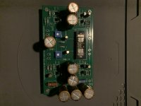
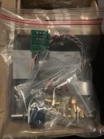
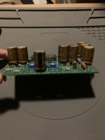
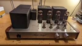
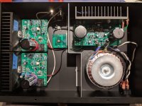
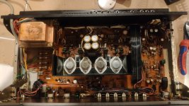
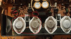
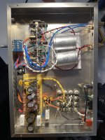
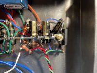
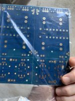
I've got three 500W +/-55V SMPS's (first attachment) that I bought from Aliexpress and eBay, two of which have faultlessly powered my 7-channel home theater power amplifier (based on LJM's L15D IRS2092 class-D modules), for more than three years now.

However, this SMPS doesn't have any effective short circuit protection, and I stupidly managed to blow up one of them by accidentally connecting it to a short circuit. That's why I've got three now - I had to buy a replacement, but I'd still like to have a go repairing this one.

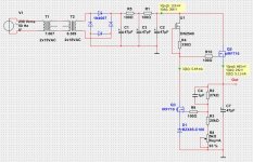
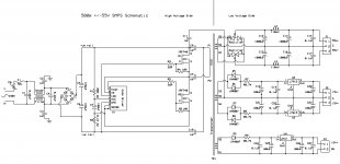
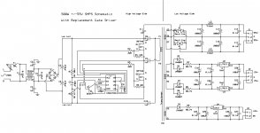
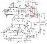
I've traced the schematic of the SMPS (second attachment) and my questions relate to the high-voltage side of the schematic, as I think I'm a bit out of my depth here.

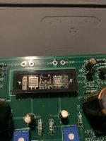
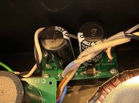
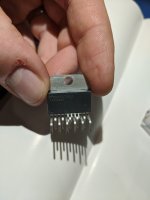
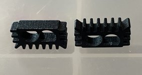
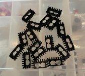
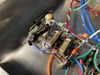
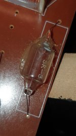
The damage included the two IRF740 MOSFETS shorted, two PCB tracks burned out, and the gate driver module destroyed. This module is a rectangular resin-encapsulated 'black box' with 7 inline pins - it has no exterior markings and I can't find any information about it.

Most of the typical SMPS designs I've seen have the junction between the mains rectified smoothing capacitors connected via a capacitor to one end of the transformer primary, and the Drain/Source junction between the two MOSFETs connected via a similar capacitor the other end of the transformer primary.

In this SMPS though, the junction between the mains rectified smoothing capacitors doesn't connect to anything else; both the +ve and -ve rails connect (via 1uF 400V capacitors) to one end of the transformer primary; and the Drain/Source junction between the two MOSFETs connected via a similar capacitor the other end of the transformer primary, same as the typical designs.

My first question is why does this SMPS have both +ve and -ve rails connected (via capacitors) to the same end of the primary transformer, and what is the effect / advantages / disadvantage of this design, versus the more typical ones?


From the schematic, I think I've figured out the pinout of the gate driver module. Pins 1&2 are joined externally on the PCB, and possibly internally in the module, and connect to R025 which I assume is a current sensing resistor. Pin 3 is V+, pin 4 V-, pin 5 is the low-side driver output, pin 6 goes to the junction of the high-side Drain and low-side Source, and pin 7 is the low-side driver output.

My second question is does anyone know a part number for this module or where I could buy a replacement? From earlier investigations, buying one from the SMPS vendor is nearly as expensive as buying a new SMPS and hardly worth the effort. But someone must be making these modules as there are many vendors of this type of SMPS on Aliexpress and eBay.


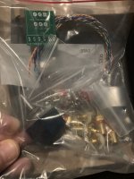
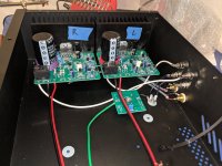
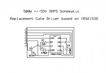
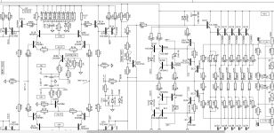
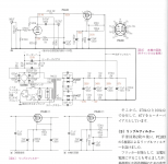
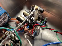
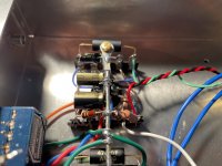
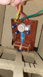
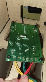
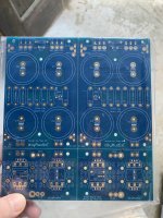
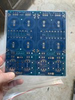
In the meantime, I've built a simple replacement based on the IRS2153D self-oscillating half-bridge driver reference model (attachment 3). I've designed the layout so that it can just plug straight into the SMPS board where the old driver was, and I've included a schematic of the SMPS with this driver (attachment 4).

My third question relates to R025 (current-sensing resistor?), which I assume is there to trigger shutdown of the IRS2153D in an over-current situation. Is my assumption correct, and will my design using BC547 work correctly? If my assumption isn't correct, what should this part of the driver schematic look like?


I've replaced both of the IRF470 MOSFETs, repaired the burnt out PCB tracks and installed my gate driver module. When I applied power, the first good thing is that there were no loud noises, and none of the magic smoke escaped. But....

The low-voltage side of the schematic has a regulated 12V output, a regulated +/-15V output and a +/-55V output which appears to be smoothed but unregulated, so the voltage presumably depends on the characteristics of the gate driver and the transformer.

... while the SMPS now seems to be working after a fashion, the +/-55V outputs quickly rise to +/-80V (or higher), at which point I quickly turn it off as I really don't understand what's happening and I'm scared it's going to blow up again!

So my fourth question is can anyone help me by explaining why the output voltage rises so much higher than it should (presumably something to do with the gate driver, as this is the only change to the original SMPS circuit), and whether there are any modifications I can make to either the gate driver or rest of the SMPS to prevent this.

Many thanks in advance,

Jon.

Attachments

  • 500wSMPSSmall.jpg
    500wSMPSSmall.jpg
    113.1 KB · Views: 653
  • SMPS Traced.jpg
    SMPS Traced.jpg
    254.9 KB · Views: 711
  • SMPS IRS2153D Gate Driver.jpg
    SMPS IRS2153D Gate Driver.jpg
    70.6 KB · Views: 683
  • SMPS with IRS2153D.jpg
    SMPS with IRS2153D.jpg
    274.8 KB · Views: 1,030

M2 Synergy Horn

Last week I did some work with Voishvillo type phase plugs, and it seemed to work out well.

I was curious to see how that would work on a Synergy Horn, so I thought I'd take a crack at it.

I think there's a fairly good chance this won't work, but the only way to find out is to build it.

Here's some pics of the model.

Je8M694.png


3AgMxki.png


MTUDRV6.png


This waveguide looks admittedly bizarre, but there's a method to my madness. As detailed here*, it is possible to 'mask' off a great deal of a radiator and still have wide bandwidth. For instance, JBL 'masks off' about 50% of the diaphragm of their EON drivers.

It occurred to me that it might be possible to do the exact same thing in a waveguide, basically take a conventional wave guide and 'fill' half of it's volume.

An externally hosted image should be here but it was not working when we last tested it.

The final shape winds up very reminiscent of the JBL M2

I did something similar two years ago : http://www.diyaudio.com/forums/multi-way/267083-synergy-horn-3d-printing-entry-20.html#post4211484


* Car Audio | DiyMobileAudio.com | Car Stereo Forum - View Single Post - Imitation
  • Like
Reactions: Kravchenko_Audio

now that we have tiny neo tweeters... any novel applications?

Occasionally fun just to throw out a thought idea. Sure that this is a total non starter, but what might be the result of this?
Surely someone has tried it? The way I've drawn it with a quick sketch just to illustrate the thought, it would be absurdly directional. But some other way of suspending the tweet in front of some variety of convex/concave parabolas?

para waveguide.jpg

Horn Design tips for cell phone

Howdy folks. I'm interested in experimenting with 3d printing technology to create fancy horns.

I currently have a Reprap Prusa 3D Printer, with a build area of about 190x190x100mm
The nice thing about the 3d printer is it's ability to handle complex shapes just as easily as very simple shapes. It just handles any 3d model 1 layer at a time, so you can make some pretty wild or intricate designs.

I was thinking a fun thing to try at first, and given my relatively small build area, would be some sort of phone dock with integrated horn/waveguide for amplifying a cell phone speaker. I realize this won't be winning any kind of awards for sound quality, but I'm interested in understanding the concepts, and seeing how much of an effect it can have. And maybe in the future using this knowledge I could scale up the idea for a full range enclosure with a serious driver in it.

So I'm wondering if anyone can provide some tips for how to design a horn profile for maximum efficiency and sound quality. Would I have to know very specific specifications(thiele&small?) of the actual driver used in the phone? I have an HTC EVO which I would be using to test this with. Is there some way I could measure or derive whichever significant parameters I would need for this?

One thing I'm curious about is if there is an optimal total length of the horn, or if you can just keep going larger and larger for more and more effect.

Here is an example of a commercial product produced for the iPhone which is the sort of thing I would be interested in doing:
AirCurve - fits iPhone 3G and original iPhone - Griffin Technology

NAD 3020 A - HELP to repair

Hello everyone,

I need help. I am trying to restore a representative of the legendary NAD 3020A

I was able to restore it to working order. I replaced all of its electrolytic capacitors, cleaned it thoroughly (it was very dirty), greased all of the trim pots, and replaced the volume gain pot.

The amp worked well and I was happy with the sound quality.

When we tried to test it with some new KEF speakers of a colleague of mine, when increasing the potentiometer to 40-50%, a flame started coming out from inside.

After inspection and measurement - the two final transistors (2N3055 and MJ2955) and the pre-final transistors (2SD669 and 2SB649) were blown on one channel, the resistor 651 was also burnt.

I have replaced the above components and now when I turn it on there is no flame, but that is only because I have not connected a load to the output. On this same channel I currently have +30 Vdc, (while on the other I have 0 Vdc). Now if I turn any speakers back on they will either burn out or burn out the transistors again or both. Fortunately, the colleague's expensive speakers are sound.


Please advise where to look for the problem. Apparently something is keeping the end transistors fully open, but I don't know what causes them to be in that state.


After I restore it, I might think about a slight upgrade with speaker protection.

Attachments

  • IMG_20220810_034121.jpg
    IMG_20220810_034121.jpg
    382.9 KB · Views: 636
  • IMG_20220810_034121.jpg
    IMG_20220810_034121.jpg
    321.1 KB · Views: 1,014
  • The burn elements.JPG
    The burn elements.JPG
    112.6 KB · Views: 628

Pioneer RX-570 Imbalance

Does anyone have any ideas on what could cause an imbalance in my Pioneer RX-570? The speakers are Marsland/ Leigh, and 6 ohm approx. The stereo was given to me in working order, I've just added my speakers. It sat for several years though.

When I dial the balance knob to the left position (approx 80% turned) , it sounds even side to side. When the knob is in the neutral detent, the left speaker is silent.

Does anyone have the service manual?

Attachments

  • 20230118_134203.jpg
    20230118_134203.jpg
    246.5 KB · Views: 99

Strange grinding GRRR sound from motorized ALPS volume pot when raising volume via remote on Sony TA-E80ES

Recently picked up a second hand Sony TA-E80ES preamp in nice and neat condition, still playing perfectly.

Although I noticed a grinding GRRR sound coming from the motorized ALPS volume pot, when raising the volume via the remote control.
When the volume is lowered via the remote, the motorized volume pot is dead silent and turns smoothly without any stottering.
Only volume up causes a slight but audible GRrrRrrrRRrrrrRrrr grinding sound. Asif this mechanical part needs some care.
No wonder, after thirty something years! I wonder:

1. Whats causing this?
2. Do you owners of E80ES preamp have this too, on Volume Up?
3. How to make the volume up as smooth and silent as the volume down? Thanks!

What to do with these FE207e?

Several years ago, I purchased a pair of Fostex FE207e drivers and proceeded to build a pair of MJK's Project 05 ML-TL. After settling on the right BSC values and adding a pair of Planet10's phase plugs, I was quite happy with the results.

Now, I'm settled in for a good while, and have no intentions of moving anytime soon (I used to move a lot). The frequent moving has not been kind to my cabinets, and I'm thinking it's time to build something else. Herein lies my question: What to build for these 207's? I've read the entire Half-Chang thread, and a good part of the Chang thread, but can't seem to locate the plans anywhere. It looks like most current efforts are understandably focused on drivers that are currently available.

So, I'll ask. What cabinet would/have you used or recommend to get the most out of the 207's? What have your experiences been?

Thanks

How proprietary are Sony's remote controls when controlling ES preamps?

I only want to control the Volume Up / Volume Down button via a thin/sleek Sony via a remote control on a TA-E80ES preamp.

Are Sony preamps strictly "married" with their designated proprietary remote controls?
Or, could various other types of remote controlls also work with premps such as the TA-E80ES?

Sony designated RM-S808 as the official remote control for the TA-E80ES.

But I wonder if a much cheaper (and more readily available and more sleeker and more ergonomical) remote such as the RM-S33 or RM-S6 could send the same Volume Up / Down signals to the Sony TA-E80ES? Thanks!

Simplicity and elegance, feedback wanted!

Hello gents (ladies?), I was hoping to get a bit of feedback on the amplifier design I've been working on, as in an amplifier design you can't have too much feedback, right? But before I arrive at what sort of feedback I'm looking for exactly please allow me to provide some background about the design.

As I was looking to busy myself during lockdown I revisited some of my earlier designs, some dating back well over a decade. This particular design initially started out as a rather elaborate exercise with lots and lots of transistors utilized to build cascodes and a plethora of precision current sources and mirrors. Then I realized that there's beauty in simplicity and elegance, so I started reducing it to something a bit more rudementary, which led me to where I'm currently at.

Upon looking at the schematic anyone that has ever dabbled with amplifier design will see the familiar three stage approach, but with optimizations left and right, let me briefly go over them to illustrate why I arrived at them:

1) The classic LTP input stage has a Wilson current mirror and features a pickoff point for the ETMC (Edmond Stuart) compensation I'm using (C12 and R37). The Wilson current mirror provided noticeable benefits over the standard current mirror, for the cost of an extra two transistors, so I figured that was worth it.

2) The current source feeding the input pair is the regular two transistor variety, nothing fancy here, I tried elaborate schemes, but those didn't seem to provide any benefit, but willing to try again if needed.

3) The VAS, to be honest I prefer to use the more correct term TIS, is your typical contraption, Q19 and R38+R39 as well as C12 and R37 provide the ETMC compensation. Q7 is the typical EF transistor with R40 used to protect Q7 during clip. Q17 serves a similar purposes but during a shortciruit at the output. Q18 makes sure the TIS can adequately drive the output stage. The TMC compensation rounds off the TIS stage and hooks directly to the output stage.

4) The output stage itself uses two pairs of Exicon lateral MOSFETs as that saves me a lot of headaches, and transistors, coming up with a foolproof protection if I had used a BJT output stage. They're biased a little beyond the point where their tempco becomes positive, which means they'll automagically provide temperature compensation. Due to the absence of a 2nd breakdown and the fact that lateral MOSFET's aren't a dead short when driven hard they have a wide SOA and I could get away with a simple protection mechanism.

Transistors Q15+Q16 and diodes D3+D4 take care of that, as they will reduce the drive voltage and limit the maximum current to about 8A per lateral MOSFET, which yields about 15A peak, more than enough for most loudspeakers.

So, and this should really have been in the first paragraph, what are the requirements I set for the design of this amplifier? Well, a balanced input paired with simplicity and elegance is one, getting as close to the proverbial holy grail of -120dB/100W/8R/20kHz is another. With the current design the simulator optimistically reports 0.0003%, or rather -110dB, so quite close to target.

Closed loop gain shows ~88 degrees at the 0dB point, and the gain plot looks nice and smooth, as does the phase plot. That, in a nutshell, sums up the design. What I would love your input on is whether there's any elegant ways to further improve performance I might have missed?

Please find the relevant plots attached, as well as the LTspice .asc file for the amplifier design.

Thanks for applying feedback! I'm looking forward to applying your ideas and hopefully further improve on the design!

Attachments

  • Like
Reactions: hpavictor

How to implement current and voltage limiting in a single supply,full bridge UCD type amplifier?

I have been designing a subwoofer amplifier for some while,I have implemented short circuit shutdown functionality ,but i'd like to have limiters with slow release that activate when the current crosses a threshold and a voltage limiter that activates when output comes near the rails,as opposed to having a fixed threshold.Pictured is the output section and short circuit shutdown sections.I know the schematic is a little messy and also the values are not exact,but I hope it can help
1674226508782.png

Buying records without owning a turntable/record player

I was surprised to see this. I would have thought almost all "record buyers" would at least have some cheap record player to play their "vinyls" on:
50% of consumers who had bought vinyl over the previous 12 months don’t even own a record player.
This was in a vaguely related article on record sales not rising the way it had for years earlier.
https://www.techradar.com/opinion/t...o-a-crashing-halt-but-dont-blame-taylor-swift

Looking to build a subwoofer. Need Recommendations.

Music only. Budget is hopefully 250 or bellow, so as not to prohibit adding another later on. Will be paired with s2000 MTM's. Looking for a design that can play from the 20's to 50hz. Prefer sound quality over SPL, but I do like my music loud occasionally. No space limitations (within reason). Will be using DSP.

What is a recommended design/sub? Looking for already tested designs or something simple that's not difficult for a newbie.

Bandpass seems more difficult than is needed and ported may be better?

Thanks.

For Sale FS: Parts for F5

I have for sale the following parts for two channels of the F5 amp as described in the schematics on page 2 here:
https://firstwatt.com/pdf/art_f5_turbo.pdf

1) One pair (2 channels) of version 3 of the store's F5 pcb:
https://diyaudiostore.com/collections/power-amplifier/products/f-5?variant=5941421764

2) 2x FQA19N20C and 2x FQA12P20 output mosfets (Q3, Q4). (These are the original output devices.)

3) 2x (2sk170BL + 2sj74BL) Toshiba jfets (Q1, Q2) (4 jfets in total; both pairs in the 8mA+ Idss range).

4) 2x ZTX450 and 2x ZTX550 bipolar transistors (Q5, Q6)

5) 4x 4.7K thermistors (TH1, TH2)

6) 4x 5k trimmer (P1, P2) (TT Electronics) , 2x 200R trimmer (P3) (Vishay)

7) All resistors (R1 - R22) The 3W ones are Panasonic (0.47R) and Vishay PR03 (100R), R3 and R4 are 2W Vishay and the rest are Vishay RN/CMF.

8) 2x blue LED and current limit resistors for the LED position on the PCBs, but not on the schematics above.

The price is $160 CAD (~115 USD) + shipping + paypal fees.

Please PM me if you are interested.

Thanks,
Dennis

All-in one streamers

I just came across an interesting new product. It is a all-in-one streamer, of which more and more products are coming to market. With this one, I was surprised with the many possibilities.It's a streamer, an amplifier and a DAC. It's especially surprising to see how many connections, both wireless and wired, can be made. It's the Arylic B50, I think they just released it.

If you look at the backside, you get a first impression of it's versatility.
  • For audio-in sources: Phono, Line-in (for many different options like TV/CD/etc.), USB. And sources can be connected both wired and wireless via Bluetooth.
  • For output, wired speakers can be connected, even a subwoofer with its own connector. But also wireless Bluetooth speakers or Bluetooth headphones can be connected.
What is special I think is that Bluetooth supports aptx HD, for the best possible audio quality via Bluetooth. And that is able to drive two Bluetooth speakers as a stereo pair. Or drive two Bluetooth headphones at the same time.

Normal list price is $139. - But in pre-ordering it can be bought for just $111.20 and comes with a remote control, 2 external antennas and a power supply.
Creating your own audio setup with this B50 is easy and versatile. It is even hybrid: analog/digital, wired/wireless combined.

For a quick overview I can recommend this video.


Schermafbeelding 2023-01-28 om 14.23.49.png

Attachments

  • Schermafbeelding 2023-01-20 om 12.01.47.png
    Schermafbeelding 2023-01-20 om 12.01.47.png
    150 KB · Views: 223

For Sale XRK audio SFP soft start board, tested, with one extra bare board

SOLD

Asking $30 to include US shipping

One complete XRK audio SFP soft start board, built and tested, and one extra bare board. with an extra unmounted optocoupler.

He asks $25 each for the bare boards.

These use the NTC's, not the resistors for inrush (present version 2.3)

https://www.diyaudio.com/community/...-pillow-sfp-ssr-soft-start-circuit-gb.350441/

if you need pictures, let me know

What is the most appropriate DIY Pass Labs design for driving original Tannoy Ardens ?

Hi everyone, can you give me some advice on what DIY Pass Lab design would best drive a set of Tannoy Dual concentric 15" Arden style speakers 92db efficiency in a medium size room. Currently using a 15W valve amp typical music levels and listen to SPL of 95db max at listening position. My preamp has a voltage gain of approximately 2 and I use a phone stage so need an amp with input sensitivity of around 1V for full power.

Cheers Johno

Allo DigiOne and Hifiberry DSP Add-On Board

Hi @All,

Is it possible to combine an Allo DigiOne with a Hifiberry DSP Add-On board?

Background:
I've build a network player with a RPi 4, picoreplayer and the Allo DigiOne. I am very satisfied with the sound and usability so far, but I need to correct some frequencies and love to have all the given possibilities of a DSP.
I've tried to install CamillaDSP, but I just can't get it to run, no matter what I try. I don't know why.

I'm very much a beginner in terms of Linux and programming.

I know that Hifiberry also has a Digi board, but if possible I would like to keep the DigiOne.

Thanks in advance

Mare

RCA vintage transformers as a passive summing box - need wiring HELP!

IMAGE 2023-01-16 11:54:04.jpg


I have a pair of these I'm going to pull from some old RCA monitor amplifiers, and convert into a passive stereo box just to send through for some color. I just am not quite sure how to read the diagram.

Am I correct in thinking that the in is 3, and the out should be 10, for the 600ohm?... but where is the ground?
Also, what effect would 150 have instead? I read somewhere some people wire switches for different tone using each ohm.

Also, where is the ground wired too?

3e Audio TPA3255 (SY-DAP1002) problem - wont leave standby (red light blinking)

Hi Folks,

Well, it's a bit of a long shot but I wonder if anyone has had this issue before or might know of a solution or way to diagnose further? Here's the problem:

Turn on the unit at the wall Red LED slow blinks:
  • If i press volume in the red light goes off and wont come back on without powering off for a few seconds at the wall
  • If i press once quickly then long press the red light stays blinking
  • Line in doesn't do anything
  • Can get th lights around the volume knob to turn on at all

This device was a gift for a friend and has been working admirably for more than a year ... naturally it's on me to find a solution 🙂 I have emailed 3e Audio (@3eaudio) on the gmail address I have used in the past but had no reply this time.

I have a USBi programmer from another project but wary of making the problem worse - though with a broken device and no other options dont really have anything to lose. Any advice on best way to proceed would be much appreciated.

Thanks!

Will.

polarization in Class A op-amp

I've read several articles on polarization in class a of the op amp's final stage, such as inserting a resistor between the power supply (negative or positive) as a current generator or btw with fets. the problem that I believe is at the basis of this solution is that in any case the dynamic parameters of the op amp change, because the current sources are not ideal. In your opinion, wouldn't it be much simpler to power the op amp with unbalanced voltages like +18 -12 ?... wouldn't the final stage work anyway in class A?

Audiosector LM4780 boards

Hello Peter,
I am one of your previous customers that bought LM4780 kit at the time and built two monoblocks in parallel mode. I used your beautiful design suggestion to just use one very thick slab of aluminium as both structural and cooling element. The amps are dead quiet and are playing beautifully for years now in my main system.
During the last "stocktake" that I did in my workshop I found a stash of 4 LM4780 chips that I've got at the time through the "sample" program, and decided to try building a bridge/parallel monoblocks if possible.

Can you please advise if you are still selling the boards and if so, can I bridge two parallel boards for one channel?
After some digging through the forum, I found this that can be used as buffer (big thanks to @juma ):

b-b.gif


This buffer converts SE signal into Balanced, but what if I already have balanced signal coming out of my media player (Cambridge CXN)?

I tried to contact you via website, but had no answer so far, appreciate any help here.

Big thanks in advance to all,
George

p1201

the amp working normaly to double 18 sub.till start to go radomly on protect.but no stable may stay for hour on or few minutes.i check and resolder all main joints.on thermal camera shows the R159 47K gets hot to 120c.another thing is i can't set the bias the pot on the hot side.trim don't respont.trim checked and is ok.replace the R159 R160 and Q114 optional.the old resistors measure on specs.have checked all resistors around idle cirquit found nothing broken any ideas what more to look at?thanks for any help.

Attachments

  • Capture.PNG p1201.PNG
    Capture.PNG p1201.PNG
    121.1 KB · Views: 89

Help troubleshooting a PCL83 Line Amp

For the life of me, I can't seem to figure out what the issue is...

I found a schematic and article (in Japanese) for a PCL83 line amp. I had most of the parts and the tubes and transformer were relatively cheap. I mocked it up in the chassis, no smoke or anything, the power supply is close to what is specified at it's test points heater is 12.6V and the rest are a touch higher than as spec'd; however, the test points in the audio circuit are way off and I can't seem to figure out how to diagnosis the issue. Specifically, Pin 1 (81.4V) is measuring about 220V and Pin 3 (2.9V) is also measuring about 220V!

The other test points on the pentode side of the PCL83 are high, with Pin 8 (312V) measuring 350V and Pin 9 (193V) measuring 205V.

I've gone over the layout and values over and over, yet can't track down the problem.

On a side note, functionally the preamp is passing signal with and without power; however, as hooked up to a junky amp there is severe attenuation as compared to the source placed directly in line with the amplifier.

This is my first build from a schematic and while I've learned a lot, I've reached the limits of my abilities. Thanks in advance for any help or suggestions.

I've attached the schematic and pics of the build with details of one channel.

Attachments

  • Screen Shot 2023-01-18 at 11.30.01 AM.png
    Screen Shot 2023-01-18 at 11.30.01 AM.png
    683.4 KB · Views: 267
  • IMG_3805.JPG
    IMG_3805.JPG
    387.1 KB · Views: 224
  • IMG_3813.JPG
    IMG_3813.JPG
    531.5 KB · Views: 158
  • IMG_3810.JPG
    IMG_3810.JPG
    394.3 KB · Views: 155
  • IMG_3809.JPG
    IMG_3809.JPG
    429.3 KB · Views: 148
  • IMG_3808.JPG
    IMG_3808.JPG
    364.6 KB · Views: 153
  • IMG_3807.JPG
    IMG_3807.JPG
    369.3 KB · Views: 150
  • IMG_3806.JPG
    IMG_3806.JPG
    434.5 KB · Views: 221

Mackie Trash 212 schematic , 3 volume pots need to be replaced.

i just got 2 of those to use as monitors for band practice,
ordered from BSWUSA,
and both have the 3 pots faulty, i need to push/press them in order to get output or crank them to the max
wish i did and attenuate my mixer output almost to no volume.

contacted MACKIE over email as they never answer the "support" phone # and they said do not sell the pots, just the whole amp assembly , 200 bux
i found out that there are a big batch of TRASH cabinets that have the faulty pots.
no wonder they called them TRASH and i tought i was just a name.... gezzzz i am pissed

contacted my nearest mackie service center and they said if the units are less than a year from the proof of purchase they will start the parts warranty claim for mackie parts
looks like they may get the pots and replace, but there is a 8 to 12 week of waiting in order to get my monitors back.

Is there a way i can measure the resistance so to order from DIGIKEY or NEWARK some pots and replace them myself, i do not want to wait 3 months.

what you guys advice.
Best.
Max.
  • Like
Reactions: indianajo

Tannoy Mercury M4 - tweeters & crossover problem

Hi everyone.
I hope you having a great weekend.
At the beginning I would like to point the fact that I am completely amateur in electronics or audio.

In my 5.0 set I have a two great tannoy speakers the only problem with them are non working tweeters. So I’ve opened the speakers to see if the tweeters are blown. The first thing which I’ve notice is the hair wires disconnected/cut. So I’ve checked the ohms with multimeter but due to a really thin wires is really hard to measure it, but when I did it, I’ve hears the noise coming from speaker so I believe they are not blow? Is it possible to solder those thin wires with connectors?

Another problem which I’ve notice is blow lamp fuse sk-3. I wonder with what currently available lamp fuse I can replace it? And will replacing this fuse fix the problem or it might be an another issue which caused fuses to blow?

Please see the attached photos.

Attachments

  • aNelbEZ.jpg
    aNelbEZ.jpg
    214.2 KB · Views: 725
  • PONKYJB.jpg
    PONKYJB.jpg
    230.7 KB · Views: 619
  • ZkzClv6.jpg
    ZkzClv6.jpg
    331.2 KB · Views: 521
  • l0pxVoS.jpg
    l0pxVoS.jpg
    222.7 KB · Views: 392
  • fWRnPbD.jpg
    fWRnPbD.jpg
    268.9 KB · Views: 426

Tweeter horn meaning when cut very high - 7200hz

I have a question about horn on compression driver. I managed to get best tone so far with: 1. Sub is 240 cm 12" tapped horn. 2. 15" long throw car speakers as mid basses. 3. Dayton PC83 as mids 4. pair of 44T30H8 cheap compression drivers stolen from Behringer passive PA speakers. My amps are Behringer NU4 for sub and midbasses. Samson Servo 200 for mids and finally ebay mono blocks for tweeters. I cut the system at 40hz(sub) , 40-235hz(midbasses) and 7200hz (mid/tweet) all done digitally in PC DAW with 42db depths. I match mids by ear which turns out to be very obvious. Different sources need little bit different volumes for mids in ranging in around 6db range. My question is what is the meaning of possible horn on compression tweeters. I feel the tone is even better without horns. Does it have any meaning when it is cut so high?

Help designing something special

Short story. Wife went back to college in her late 30s while working more than full time in a salaried position and finishes a degree in forensic anthropology in a couple weeks. I'm proud and wanted to get her something she'd like. I bought her a 400 year old anatomy text book as a graduation gift. I'm building a pedestal to display it on. A couple years ago I finally started building a pair of ikea wood bowl speakers with some Tang Band drivers I had had sitting around for a decade. I didn't finish. But I was just thinking, what if I did finish and the pedestal was also a subwoofer to go with them. Boom! I have a guy doing some cnc carving in the 4 side panels, but I think they're 13" wide with the carvings being like 9" wide. The panels are 36" tall but the carving is 28". Anyone wanna help design something functional within those parameters?

I was thinking something about this shape: pillar

The panels are 1" thick and I'm not talking about a 12" sub here so that should be fine. Can integrate some internal bracing to adjust shape or volume. Down firing is the only thing that would make sense to me, wife approval factor needs to be high since it's for her after all. I can confirm the exact drivers I have later if someone is interested in helping, they're buried in the garage.
  • Like
Reactions: Moondog55

Scott A426 playing only left channel when using phono input - HELP!!

Hi everyone, I am having a big headache in trying to figure out why my Scott A426 is playing on the left channel only when i use the phono input.

The turntable is working fine, been tested with another receiver, cables etc all is ok.

As this happens only when i select the phono input (everything works ok when using any other input), I thought it could have been an issue with the pre amp board. So far I have tested the caps and transistors on the board and all seem to be within range. All contacts seems ok, nothing look loose etc...

Any idea what should I look for next?

Thanks in advance!

For Sale EU: DIY Hypex NC502MP Amplifier

SOLD

For sale is my stereo amplifier based on Hypex NC502MP. All connectors on the back panel are quality parts by Schurter (IEC), Neutrik (XLR) and Cliff binding posts, which allow using banana plugs or bare wires, internal speaker wire is 4Connect 2.5mm2 OFC. Listened to it for < 100 hours with underpowered bookshelf speakers (ATC SCM 11) so it was never pushed near its limits.

Only XLR inputs are wired because I don't have any unbalanced sources but you can just use RCA to XLR cables or resolder the custom input PCB to use the Neutrik RCAs that are already there if you don't have balanced outputs on your source.

The Hypex module itself is bolted to the aluminium chassis bottom lid and thermal paste is used between the module and enclosure. The enclosure itself is the ModuShop(Hifi2000) Galaxy Maggiorato GX283 which looks and feels solid. It is made of black oxidized aluminum with a 10mm thick face plate and allows for effective heat dissipation.

Dimensions: 230 (W) x 86mm (H) x 245mm (D).

Price: SOLD

For Sale Semisouth SJEP120R100 pair of SIC JFETs

SOLD

Asking $225 $195 for the pair, including US shipping.


I will not be using this pair of Semisouth Jfets, so here they are for sale.

I used 4 other pairs of these jfets from the same seller, and all tested and worked as expected.

This pair tested correctly for the on voltage of around 2.5 volts, and my transistor tester sees these as a jfet, not bjt.

I will ship via USPS Priority Mail.

IMG_1402.JPGIMG_1403.JPGIMG_1404.JPGIMG_1405.JPG
  • Like
Reactions: mordikai

Step-up transformer

Hello,

I have been a forum member since 2005. Unfortunately, I have been unable to login as 355f1no matter how hard customer service tried to fix my email problem and I had to register again.

I recently brought a Meridian 551 integrated amplifier from the UK, it was a gift. file:///C:/Users/vigna/Downloads/hfe_meridian_551_user_guide_en.pdf

I plan to use a step-up 500W transformer - will be located in another room - and would like to know if this VZolution would be a sensible choice.

Best regards,

https://www.ebay.com/itm/3639474463...rentrq:c86f7f711850ab84773cdbb1fffe76a6|iid:1

Projects by fanatics, for fanatics
Get answers and advice for everyone wanting to learn the art of audio.
Join the Community
507,744
Members
7,886,464
Messages

Filter

Forum Statistics

Threads
406,154
Messages
7,886,464
Members
507,744
Latest member
HMac60