My first GB

Finally, I´m starting GB for printed circuit board for following products:
- PASS F6 PSU - DIY-NR002
10 boards: 176x168x2mm; HAL; 70µm; SILK TOP/BOT; GRN/WHITE
(ordered: @2 PicoDumbs)
- PASS M2 - DIY-NR003
20 boards: 110x120x2mm; HAL; 70µm; SILK TOP; GRN/WHITE
(ordered 1 pair: @MASantos, @wrath; @brianco;@kweeSong lim; @Cambe; @mk57; @vvs57)
- PASS F6 NITROUS - DIY-NR004
20 boards: 110x103x2mm; HAL; 70µm; SILK TOP; GRN/WHITE
(ordered 1pair: @2 PicoDumbs)
- PASS ACA - DIY-NR005
10 boards: 100x80,5x2mm; HAL; 70µm; SILK TOP; GRN/WHITE
- XRK-BF862 HPA (with charger) - DIY-NR006
10 boards: 102x72x1.6mm; ENIG; 35µm; GRN/WHITE


Actually price without postage for this quantities from 14€ and 30€ for F6 SUPPLY.

Following product finished this weekend:
- SUDSEPP - DIY-NR007


Following products before end of next week:
- ZM IRON-PRE (both versions and batteries supply) - DIY-NR008
- JUMA-BF862-PREAMP+CUBIE3 (one big board with LDR volume control) - DIY-NR009


In the line:
- all BOM´s

Would be nice to close first GB end of next week.

JP
Why should I buy a field coil driver and which?

Hello all.
Been on the FR journey in OB set-up for a while. Started like most of with a okay entry level driver. Still following the news threads and hanging on I like to see if I can find a better driver. What I miss is more extension in the HF and I also want a driver that has a wider dispertion. I use a LF for the lows and I wish not to add a HF driver.

I started to study the history / development of FR drivers and can conclude that field coil drivers still should be the absolut best. History shows this time line: field coil => alnico => ferrit => neodyn………I habve seen drivers with extreme high magnetic fields achieved with permanent magnets. I do understand that you in field coil driver change the T/S by adjusting the supplied voltage. Primary changes is efficency and the QTS. I read that some claim the benefit is the ability to change the QTS but why? If used in a horn then I see a benefit to tune primary the LF output since the change by adjusting the osu supply is how you want the “bump” in the LF. While in OB I dont see an direct benefit. 1) Most FR gets support from LF drivers, they a re connected to a crossover so the QTS trim shouldn’t matter. 2) Efficeincy = can easy be adjusted with a L-Pad. And lowering the effciiency in the FR is what most end up doing. So then my question is - what is the benefit of purchasing a expensive set field coils? If you on top of your contribution I would appreciate if you also have some recomendations. Thanks in advance……..Mike

Acoustic lens on a full-range?

Has anyone tried to affix one of those beautiful JBL type slotted lens in front of a full-ranger?
The horrific beaming at high frequencies seems to be the perpetual Achilles heel that holds us full-rangers back from greatness. No doubt the careful expansion rates within horns really "makes" those lens' work as well as they do....& the gaps & the expansion inconsistencies just might make the whole thing "fall apart".
Has anyone got any ideas?


----------------------------------------------------------------------------Rick....

Attachments

  • acoustic_lens_2.jpg
    acoustic_lens_2.jpg
    90.8 KB · Views: 2,046

Threshold T-200 power switch help

I have a Threshold T-200 amp which was sent to the factory to do the Stasis 7 upgrade. I have it hooked up to a pair of Wilson Watt Puppy 7s . The power switch has always been very difficult to flip and I actually have to use a certain angle from the bottom of the front of the amp chassis to gain the leverage to get it to flip on. A few months ago I was flipping it on and once the amp powered on, I heard a pop through the speakers and then hum. I immediately powered down the amp and thankfully there was no damage to my speakers.

I was going to have someone look at it before re-inserting the amp back into the system. I decided to put it back in, but using my cheap-o test speakers. The amp powered on and there was no pop or humming. The amp operates fine. Just wondering if this was an anomaly, and is there any alternatives to perhaps installing a less resistive power switch.

I am over in the Sacramento area and near Jon Soderberg but not sure if he is still taking in repairs.

Thanks
  • Like
Reactions: Mikerodrig27

Does anyone have the service manual for the sony MEX-N5300BT headunit?

Hello all, is there anyone here that has the service/repair manual (NOT USER MANUAL!) to Sony's mex-n5300bt headunit? I cannot find it anywhere on the internet, except here, and they require you to pass a difficult test to be able to download it, and it's in Russian. If anyone can retrieve that manual, I would be grateful!

Thanks in advance.

2.5 kHz quality price tweeter?

Which tw will you match with a pair of SB16PFC25-8 midwoofer? xover cross about 2300/2500hz 18db/oct

i'm uncertain on these drivers. On vituixcad them have good response, with a no complex xover.

1. Seas 22TFF
2. SB29RDNC / SB29RDC
3. ScanSpeak R2604/83300 (nice fr but i don't like off-axis response, maybe on monitor system can be fitted better)
4. Seas 27TFFC

as you can see i need about 93/94 db's 2.83v due to pair of midwoofer 8ohm ..
i don't ear any of these anymore, on datasheet they are good but i wish to ask you better advice.
Thanks

Classic view, visited/unvisited

I saw in the change log that: "The classic theme front page now has the original classic pre-migration font and colors for visited and unvisited threads."
https://www.diyaudio.com/community/threads/change-log.380502/page-2


On Chrome 109.0.5414.120 on Windows, there's now almost no contrast between visited and unvisited threads. I'm not sure what drove this change, but on my computer it's a bad one. The contrast was a lot better a day ago.

I tried changing font size from medium to large, to small, and that didn't help.

Question about Zener-Transistor regulator

I am working on a vintage stereo receiver that has a rather poor phono pre-amp.

As a result, I built my own from Rod Elliots site. Works great.

Now, I would like to install this phono pre-amp board inside the stereo (don't want any external extra boxes, etc). Problem is: the NE5532 is +/- 15 and the only voltages I have inside the unit are +/- 26 volts and +/- 35 volts.

I got a couple DC buck/boost converter (PWM controlled) all-in-one boards I could use, but rather keep this linear to ensure no extra noise is introduced. Thus, I scraped around online and came across the classic "Zener/Transistor" regulator diagrams..

Here is one I am looking at:

zr1.gif


Now, I think I understand how this works and - please correct me if I am wrong here - but given MY supply (input) voltage, I will not be able to use a general 2n2222 or similar transistor, correct?

BASED ON THE VOLTAGES REFERENCED ABOVE...

My understanding is: once powered up, as long as the voltage across RL is 5.05 volts, the effective voltage between the base and emiter is essentially becomes 0 - and the transistor turns off.. hence "following" the voltage of the zener. BUT... at the moment the circuit is powered on, the voltage between base and emiter becoes the full regulated potential, thus..

In MY OWN scenario - where input voltage is around 26-28 volts, and regulated voltage would be 15... the E-B junction will see the full 15 volts when power is first applied - correct?

Meaning... I would not be able to use a simple general purpose NPN for this, correct?

I also have the "negative version" of this circuit using the zener in reverse and a PNP transistor. So my plan is to "mirror" this for the negative rail.

Thanks!

Still fuzzy on adding a Subwoofer to bridged ACA monoblocks

Having read these threads, and being a less technical DIYer, still not clear about if or how to safely add a SINGLE subwoofer to my bridged ACA monoblocks.

I am using smaller speakers and on other set ups i’ve enjoyed what a decent sub can do for overall soundstage etc. curious to know if i can take the ACAs a small notch higher.

I would use high level connects betw the ACAs and the sub.

Can i safely connect REL using their approach or an SVS sub using their standard (4) speaker connects?

How to check for problematic ground issues?

Is the reversed polarity a concern?

See, a very non-technical solder by numbers DIYer.

Any insight is appreciated. Its been great fun to build the ACAs and an ACP+ for my first builds.

Chuck

Adding Sequerra T1 to AK-2 Klipschorn?

Hi all! While not quite as diy as other projects I’ve worked on I’m hoping the great folks here can help out.

I have a pair of 1980s klipschorns with the ak2 crossovers. My room isn’t quite ideal and has around 20’ between the two which leaves a less than ideal stage. I’m hoping to add a pair of t1 ribbon tweeters from sequerra/pyramid to aim into the listening position and help fill the hole a bit.

My question is I’m not 100% sure where the best place to wire the new tweeter in would be.

Thoughts:
I can tap into the full signal out of my amp, or the HF taps on the bass bins( leaving the existing tweeter connected) , or removing the existing tweet and going to the ribbon instead.

Unsure how this would impact the impedance and I’m a bit reluctant to tear apart the k horns to experiment if I don’t have to. I have DATS and a calibrated mic to check thinks over once done.

Thanks for the input!

Moodeaudio - volume delay

Hello everyone - this is my first post here and if I did something wrong I apologize in advance 🙂 I have a question - is there any way to make the volume control follow the knob? At the moment, it works tragically - the delay can be up to 10 seconds, it looks like some kind of default behavior of the player, I've had moodeaudio for a year now and I've tried many versions. I am not interested in multiroom or even the indication of this knob on the screen, if the gain adjustment using the python script and moxer audio will work efficiently, it will be enough for me, has anyone tried such solutions? or another?

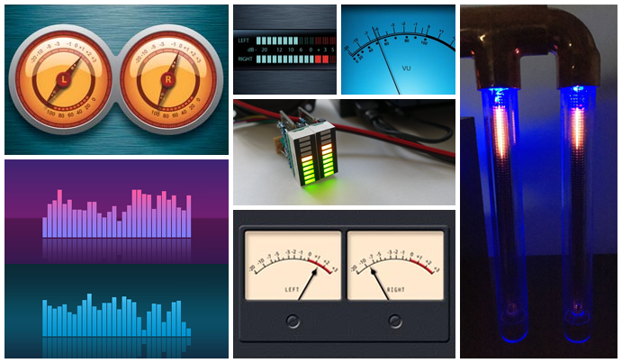
peppyalsa - ALSA plugin for VU Meters and Spectrum Analyzers

peppyalsa plugin is the result of the long and productive discussion in the PeppyMeter thread:
https://www.diyaudio.com/forums/pc-based/291010-peppymeter.html


peppyalsa is the ALSA plugin which sends a current audio volume level to a named pipe. Any application written in any language (e.g. C, C++, Java, Python etc.) can read that data from the other end of the named pipe and use it for its own purposes. The most common usage is displaying volume level either in GUI or in some hardware device.


Another functionality provided by peppyalsa is a Spectrum Analyzer. The plugin sends amplitude signal for each frequency band to a specified named pipe. Any application can read that data from the other end of the named pipe and either display it in GUI or in some hardware device.


peppyalsa.png


More details about plugin can be found on the wiki pages:
Home * project-owner/peppyalsa.doc Wiki * GitHub

Using the LM317 with higher voltages

Some time ago I had seen a variation of an LM317/337 power supply in The Audio Amateur but applied for higher voltages that it was designed for.

In theory, the LM317/337 regulators, as well as the LT1083, accept up to 37v inputs. But in fact what it can't accept is a 37v difference between input and output.

So you can feed higher voltage at the regulator's input as long as the difference with the output voltage does not exceed 37v. Right?

What you does lose is protection, particularly from output short-circuit.

If I remember well, and that is what I am asking a suggestion for, what you had to use was to add a zener diode voltage between the regulator's output and input. If I remember well that zener was between 37v and 39v.

Do you agree with such a regulator as safe to use?

In that TAA article the regulator was used on a Hafler power amp, feeding a higher regulated voltage to the low current stages, leaving just the power output unregulated.

Most amplifiers use such a solution, but sometimes the regulator they used there is not that good, and I think a 317/337 pair would work well.

What do you think? What would you suggest?

Help with this circuit

Hello,
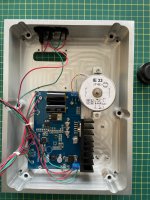
I have a seperate motor unit for my turntable, I originally wanted to replace the fine speed potentiometers to help get a more accurate speed out of the motor. I opened up the motor unit and am a little confused. It is 24v DC going in,powered by a 24 v DC linear power supply, but the motor is 12v AC. I would be very grateful if someone could look at the circuit board and explain to me what is going on, ultimately what I would like is to fit a better motor that has better speed stability. 24v DC motors appear to be the way ahead in this regard.
I have attached a couple of pictures, the first being the ciruit board and the motor. The second is the underside of the lid. The square board is an LED display, which shows either 33 or 45, the boards on the left are, from the bottom, 45 rpm fine speed pot, then 33 fine speed pot, next is the 33/45 selector switch and the top is the motor on/ off switch.

Thank you

Attachments

  • 08C4FF13-118C-49BF-8556-755E455E7B03.jpeg
    08C4FF13-118C-49BF-8556-755E455E7B03.jpeg
    482.6 KB · Views: 105
  • E9647C91-4314-4DF8-BE51-82A98FD8FA05.jpeg
    E9647C91-4314-4DF8-BE51-82A98FD8FA05.jpeg
    560.2 KB · Views: 90
  • F072696E-38D5-447F-BCAE-CFB165CB765D.jpeg
    F072696E-38D5-447F-BCAE-CFB165CB765D.jpeg
    116.5 KB · Views: 87

Help me make sense of this ESS schematic

This is what's written on the datasheet.

Paralleling DAC outputs as shown in Figure 1 is a technique used to further improve DNR and SNR performance. The ES9038PRO has a low output impedance (typ. 202ohm) and paralleling DAC outputs will further reduce the output impedance. Paralleling 4 channels as shown in Figure 1 will result in a 50ohm output impedance. Paralleling 8 channels will result in 25ohm. Many op amps used for the I/V stage (U1 and U3) to drive such a low impedance will have difficulty maintaining low THD and linearity. For the ES9038PRO, it is recommended to parallel DAC outputs after the output of U2 and use a set of op amps (U1, U2, U3) for all 8 channels.

If the design uses 2 ES9038pro chips which is the most I've seen in commercial designs, does it mean a balanced output would have 3 opamps (per + or - channel) between the DAC chip and the XLR connector? (so 12 opamps minimum for R+, R-, L+ and L- channels)

Thanks

1320B89E-566D-4A0A-9005-F1C77C971609.jpeg

Tweeter help please

Hi. I am thinking of changing the tweeters in my speakers. They are currently the Morel MDT30S and are approximately 20 years old or so. I don't know the exact age, as the speakers are second hand, however, they still work. Recently, I accidently pushed in one of the silk tweeters, which were popped back into place via the vacuum cleaner! I tested the tweeter afterwards by playing music and it worked with no distortion.

However, I have had two different responses on what I should do. One retailer said that although the tweeter will work, it will not be the same as before even though it appears with the eye to be ok (there is just the slightest crease on the surface). The second retailer said that as long as there is no distortion and it plays, then it is fine.

Now, I can get hold of a replacement set of the original tweeters but should I look to buy the replacement which is the CAT 308? The specs are very similar to the MDT30S, so would I hear any evidence of an upgrade to the sound? Although the flange on the newer tweeter is wider, I can use the flange from the old tweeter as the screws are in the same position. The CAT308 will be 3 times the cost though!

Discuss!

Repair help needed - Alesis Transactive Drummer - TDA7294

Hi!
I should've made this thread a bit earlier, but it's finally reached the point where I think I can't go on any further on my own. I received this amplifier as a hobby repair project. I'll try to be succint in my description to avoid making the post too long to read

Failure
It was accidentally switched over from 230V to 115V, as the switch is exposed. The fuse blew and the amp shrieked for a while and died.
Early analysis
I found a blown up TDA7294 and remains of two capacitors (C24 and C25). The capacitors have exploded their remains all over the board, which I've cleaned up. Later I learned that those were the caps on the MUTE and STBY lines. I've replaced the chip, plugged everything back, switched the amp to correct voltage, replaced the fuse and turned it on. The speaker shrieked and the TDA started to smoke immediately.
Repair attempts
There's no schematic or repair manual available. As such, at first i attempted to poke around the amp a bit. I've built a current limiter on a 60W incandescent bulb in series. I've measured the voltages with the chip unsoldered, but it didn't make much sense, so I tried to build a TDA reference schematic on a breadboard, but failed. Later on I've learned (also through this forum) that it's such a finnicky beast. I blew up three more TDAs while testing it with various power limiters (a pair of lab supplies, current limiter etc.).
Current state
I have written down about 95% of the schematic and the PCB to help with understanding the problem. I've looked at the MUTE and STBY lines but they have always properly reported as +7.5V from ground for me, with the delay capacitor charging over 1s, which I checked on the scope. That being said, every time I put a new chip in (speaker and input disconnected) my current limiter bulb is a bit too bright for my taste, and the supply voltages sag significantly. The last two chips I've fried trying to solder their connections one by one, starting with the negative supply, trying to figure out what could be causing the problem.
Vdd = 40V, Vss = -40V, GND is at 0, input at 0. With the chip in, output has shown DC bias. It's hard to measure voltages accurately as the chip is actively trying to fry itself anytime i put one in. I've also damaged the board pads slightly, as soldering and desoldering a 15-pin chip repeatedly takes its toll.
Files
I've attached a zip with my KiCAD project, with the schematics and PCB. I'm also attaching photos for reference.

1675083652062.png

1675083634595.png

EDIT: some P.S.
  • I can post images of the schematics if people don't generally use KiCAD - it's much easier to browse them in the software, especially considering that with the accompanying PCB you can quickly locate the components physically on the board.
  • The schematics might have errors - especially around the component values (measured in situ) and the input section which I didn't really work on too much - just to clear things out.
  • The PCB is made just for verifying connections, so it's missing large areas etc. - I am thinking about sending it to fab, but I'd improve it like the original first.
  • The total count of dead TDA7294's (including the one in the initial catastrophe): 7

Attachments

Current sensing on mains connection

I'm looking to build a mains filter for one of my systems based on the Fo-Felix design I found here.

Now, I had this idea about adding an indicator for each output, to show if a device is connected and drawing power. Bit by bit I researched my way into current sensing transformers and figured that I could use one, coupled with a transistor, to drive a white LED on the front panel. Making it go on/off would be relatively easy, but I decided to make this into a learning project as well, so why not make it vary its intensity with the current draw as well?

With the help of a friend I put together this schematic in LTSpice and it seems to do what I want: drive the LED at about 4mA for 0.1mA of transformer current and at 40mA for 1mA input (assuming 1:1000 transformer ratio, so mains draw would be 100mA -> 1A, the top end being mostly theoretical).

I'd be curious for some feedback on this, especially since I've gotten to a point where LTSpice will take "forever" to simulate the circuit if I change any value/part (so either spice is broken or there's something wrong with my circuit).

Screenshot 2023-01-30 at 09.54.45.png

Undervoltage protection and shut off schematics

I am a newbie, so my apologies if anything is wrong with my question. I am building a +/-18V 0.3A power supply for my phono preamp. The supply is fed by 4 LiFePO4 batteries (2+2). When fully charged, each battery is close to 13.5V, so the maximum input voltage is +/-27V. When any battery is drained to 10V, it shuts itself off completely. This would make the input voltage drop on one side with unpredictable and potentially dangerous outcomes. I'd like to use a simple protection circuit to shut off the input voltage completely when any of 4 batteries approaches the 10V threshold. I have no experience with such circuits, so here is just my intuitive wish list:

1. 4 sensors, each monitoring the voltage of one battery (perhaps based on a voltage reference driving an opamp?)

2. A relay with mechanical (or hercon) contacts. The relay feeds itself - once disconnected, it cannot reconnect without me pushing the start button.

3. One relay disconnects both +27 and -27 inputs (or whatever the voltage is by then) - disconnects all batteries from the power supply - as soon as any one of the 4 sensors is triggered by the voltage of any battery dropping below a chosen threshold.

4. Ideally a LED turning on or off as an indicator that the protection has triggered.

I would appreciate any thoughts, links, schematics, parts suggestions, etc. Thank you for your help and expertise!

- Alex

Looking for Trio KA-8100 schematic

Hi All,

I'm running out of online resources to find a schematic for a Trio KA-8100. It's a Japanese Trio-Kenwood and the USA equivalent is a Kenwood KA-601...and I have that SM. Problem is, the phono preamp circuitry is different in the Japanese model since it also supports a MC cartridge input. I think the Trio KA-8300 -- next model up -- has the same phono preamp circuit design, so that would work as well. Thanks.

Going lower than the rated crossover frequency of a horn

Hi I have a horn that is rated to be crossed at 800hz and a driver rated for 300hz. I'm planning to experiment with different crossover frequencies below 800hz using DSP and equalization as it's a bi amplified active crossed system. In addition, I am curious if I can further achieve the desired frequency by incorporating a plain wave tube type of equal diameter to the horn thoat and driver throat -- effectively extending the horns throat section anywhere from maybe 3-12". Any thoughts?

PCB file Gerber for audio projects

On my Patreon platform you will find many audio projects complete with instructions and the possibility of downloading gerber files useful for personal printing of printed circuit boards.
Patreon is a monthly paid site with three levels of subscriptions where you will find not only interesting electronic-audio projects but also small construction guides.
Here the link, thanks
link Patreon pcb-audio

Anti-clip, limiter, compressing, quick wins?

Well my first attempt at an anti-clip "works", but it's not great. Need work.

How do I know I have or will clip? I am processing 16 or 24 bit audio in a 32bit word. Therefore if the value won't fit back into it's 16bit or 24bit word it will clip.

What can I do about it?

My first attempt was... decrement the "pre gain" value by 10% and cut the offending sample by a factor of 0.75.
The pre-gain value is then increased when there are no clips by a factor of about 0.00001 per sample.

I mean it's a bit of a butchers attempt at a limiter.

In practice what it does do very well is stop the ultimate blasting "fart" sound caused by bass clipping digitally. Instead I get a subtle clicking.

Trying to tune it reveals the clicking is most likely caused by the sample scaling factor. If it's too small, the clip happens at least the first time, "Click", if it's too large, it effectively inserts a bogus corrupt (too low magnitude) sample in it's place "click".

An expensive approach is to do the clip calculation in a while loop...

while( stillClipped() ) {
gain -= 0.01;
recalculateSample();
}

But I don't have that kind of time/luxury, I need an instant response.

Putting compression asides. What I really want is a HARD limiter. In my experience of using various audio and video software packages on PC which almost always come with some form of hard limiter plug in. However I don't think I've met one that worked perfectly. You can always blow through them, particular with EQ.

Putting it in here... "Don't drive it that hard. If it clips at 0db, aim for a meter level of -6db and occasional transients are then -3db. Yes, yes, yes I know. I have no GUI on my EQ, so to tweak settings I have to edit code and rebuild, so it's "scrappy". I'm hitting the clip a lot.

Not many people get this approach, but I tend to "keep my baggage" when developing/engineering. If a problem manifests during development don't just jump to fix the root cause, instead use it as an opportunity, for some negative testing, to make the project, adaptive, accommodating or at least protect itself and others from the mistake and do something sensible.

In that regard the clicking is just a nice reminder to fix the gain structure and stop being lazy. However, while I could flash a red LED and move on from here.... I want to spend some time trying to get the "Anti-Clip", "Hard last-resort limiter" a little better first.

Any suggestions or articles to read on techniques?

Pentode nonlinearity at low levels of drive voltage

Datasheet plots of input voltage, current, distortion and power output have a curious nonlinearity at the origen of the input voltage curve. The plot usually rises steeply and then bends slowly to form a (somewhat) straight line for most of the graph. This implies that power output is not linear for very low input levels, becoming (more) linear only at higher input voltages.

What is the reason for this behavior? It is present for different tubes, different manufacturers, so seems intrinsic. But I don't recall reading any mention of this effect.

It would seem to imply a kind of compression for very small signals.
Charging up a capacitance comes to mind, since there is linearity at higher levels.

Am I just not using the right words and search terms?

Sony TA-1010 motorboating

This is my first post here and as Dutch is my primary language I want to apologize in advance for my Dunglish 😉

I'm busy with a Sony TA-1010 that had several problems and by now is driving me mad. When I got it there was a loud buzz so I didn’t test it thoroughly as most of the time the basic things like replacing bad caps and cleaning already solve a lot of the problems.

Some of the things I have done already:
  • Cleaned switches and pots
  • Replaced the volume pot as the old one was too far gone.
  • Replaced all electrolytic caps with Nichicon FG caps except the main power supply cap C135 (1000µF/63v) as this measured fine. Most other caps were on their way out with either a high dissipation factor or a high ESR.
  • Replaced C120/C220 .02µF tantalum caps for 0.22µF Nichicon FG caps
  • Replaced the trimpots with Piher PT15 ones as the old ones were fluctuating a lot. The pots are set at approximately the same settings as the old ones (measured them before adjusting them).
  • Replaced R152 (6800 ohm's) as it was cracked and the resistance varied

The problem I have is that the left channel is motorboating. It seems to be coming from something on the amplifier board. When I take away the left input and short it with a 1K ohm resistor the problem still persists. Probing around it looked like C125 was leaking as it measured around 600 ohms in circuit . I didn't have 370pF laying around so I replaced it with a 330pF but this didn’t solve the problem. The 600 ohms measurement is gone... As the right channel plays as it’s supposed to do I don't expect it to be a power supply problem.

Does anyone have suggestions where to look?

The smell of your hobby

22 years ago I let go this familly inherited hobby for electronics , but I realized that the thing that I like the most about diy electronics is the smell of old solder with old tree resin which is very different than today's solder, feeling almost like a religious church ceremony where the priest makes fumes burning all sorts of resins and it's not like burning aromating sticks...It's very different first because it happens once a week and only for 4 or 5 times during a 5..6 hours religious ceremony..Well I barelly attended one or two in a decade , but from time to time I desolder some components from 40...60 years old pcb's and I realize how good that old resin smell feels, almost like a lost religion habit, almost like real leather, unlike today's solder or flux.If I'd do a shoe once again I'd do it for the leather smell...well the glues are pretty toxic and bad smelling, but if you ever had around at least a few meters of real leather you know what I mean.Some like contact glue though... 🙂
I should've probably been a perfume maker...As I'm mostly single for two decades now I can only remember my mother's perfumes...they were cheap and never riveled my first girlfriend perfume that was about 300 bucks for 50ml cause she had rich parents...but I wonder why I never got involved with the perfume industry.I didn't like chemistry too much yet It would have been a feast every day, unless there's a danger of getting acoustomed and saturated with those smells too...I don't see myself a seller or user of anything expensive...mostly a manufacturer and experiment addicted guy so there wasn't much chance to get into this expensive smelly bussiness...Probably the real secret in life is the scarcity of very fine essences yet If I'd be a billionaire , I could buy all the most expensive shoes in the world, but once finished they don't smell much, could have some ladies using the most expensive perfumes though...I probably need to be a billionaire cause I'd need to pay for those damn perfumes...or I could just enjoy the smell of old good solder and real tree resin...cause I don't even wear leather shoes these days...although I have a pair of Church leather shoes for very rare ocasions...
Login to view embedded media

Recommend me a sweet 10-20W design

A plea to all you wise tube heads... I'm a constructor (not designer) looking for a design to build but am punch drunk at the number of choices out there. I need 10-20w into 4ohms. It must have great resolution, excellent transparency in the treble especially, and throw a nice walk in soundstage. The rest can take a back seat. I have experience of a KT88 PP amp which was a bit brash, also a triode strapped EL34 which was very good. The rest? No idea. I am willing to spend medium money on parts and take my time. Based in the UK. Thank you in advance for any words of wisdom.

Spice model for 811a A2 Grid

Hi!

Glad to be back after almost a decade, any one has a good spice model for the grid circuit of a 811A?

I'm using this at the moment and the grid current draw in A2 mode doesnt seem right.

At 430v @ 100ma, Vg +22, the model only draws 3ma, I believe from reading tubelabs comments in 2007, Ig should be like 20ma or there abouts.

any help is greatly appreciated


.subckt 811a 1 2 3 ;
+ params: mu=160 ex=1.317 kg1=1350 kp=100 kvb=1400 rgi=2000
+ ccg=2.3p cgp=2.4p ccp=.9p
+ a=1.6667e-10 b=-.0000002875 c=0.0001758333 d=1.275
e1 7 0 value=
+{v(1,3)/kp*log(1+exp(kp*(1/mu+v(2,3)/sqrt(kvb+v(1,3)*v(1,3)))))}
re1 7 0 1g
e2 8 0 value=
+{a*v(1,3)*v(1,3)*v(1,3)+b*v(1,3)*v(1,3)+c*v(1,3)+d}
re2 8 0 1g
e3 9 0 table {v(2,3)} =
+ (-1 1.1e-16)
+ (0, .6e-4) (20, 5.38e-4)
+ (40, 6.25e-4) (60, 7.41e-4)
re3 9 0 1g
g1 1 3 value= {(pwr(v(7),v(8))+pwrs(v(7),v(8)))*v(9)}
rcp 1 3 100k
c1 2 3 {ccg}
c2 1 2 {cgp}
c3 1 3 {ccp}
r1 2 5 {rgi}
d3 5 3 dx
.model dx d(is=70u rs=1 cjo=1pf N=180)
.ends

Ice power 200asc output problem

Hello i have an problem. I have 8 ice power 200asc amplifiers and only one have 100%output, next one have 70% , rest of them 5-20%. I have change all fouly tht capacitors, nothing have change. Measured for short all transistors, capacitors, diodes. Everythnik looks okey. Power supply section work properly and have 47vdc , +-12vdc. Where is the problem? Very thanks.
20230131_210334.jpg
20230131_210343.jpg

What are these drivers worth?

Should I purchase? These are for sale locally for 950.00.
Looks like a DIY Jensen bass reflex cab with JBL drivers and crossover.

Attachments

  • 306413848_6153566684659441_8680936155200139235_n.jpg
    306413848_6153566684659441_8680936155200139235_n.jpg
    140.7 KB · Views: 166
  • 328527436_882430189627606_4023857935650631680_n.jpg
    328527436_882430189627606_4023857935650631680_n.jpg
    420.9 KB · Views: 167
  • 328622994_870039080881615_3690498757863175902_n.jpg
    328622994_870039080881615_3690498757863175902_n.jpg
    565.9 KB · Views: 157

Vintage Magnevox turned new again

Hello all, thought I'd share my current project. I had some old magnevox speakers lying around, very old stuff and sounded quite poor (looking at the picture now I realize how funny that might sound). I've had a lot of parts lying around waiting to be used and figured I could save myself a bit of time building a new cabinet, and use the old junk magnevox. The exterior and construction of the cabinet are fine, so it just needed a new baffle.

20221231_131832.jpg

A new baffle was cut from fairly cheap plywood I had lying around. It seemed to machine fine enough and I wanted to keep costs low on this one given the cabinets cheap chipboard.
I have a DX25 inside a WG300, and some Peerless 160f25pro01, wg adapters were printed by a friend for free. Next up is mostly waiting on PE to get back to me on a potentially bad measurement mic, hopefully things will be warm by then and I can get some nice measurements to start working on the crossover.
Not sure about keeping the cabinet ported or sealed, will have to see what this driver likes in winisd.

20230103_123416.jpg

Recommend me: Optical(SPDIF) in, 20W stereo out, Class D IC

My desktop powered monitors have developed mains leakage on their ground and it's time they (or at least their PSU and amp) went.

I figured I might do some DIY on it. I really like the look of the automotive style ICs like these:
https://www.infineon.com/cms/en/pro...grated-class-d-audio-amplifier-ics/ma2304dns/

However, it would be awfully cool if I can expand my options and then narrow them back down to something I can pick up in "dev module" or "eval board" format to... well evaluate it. Initially skipping PCB dev and starting breadboards.

I know all the main manufacturers make these chips so there is a wide range. I'm just trying to pick a few options to start on. If I search for this area on Amazon or AliExpress (where I would usually look for eval boards) I obviously get all manor of snake oil rubbish... where it seems that the colour of the capacitors has more value to the buyer than the actual facts.

I know that TI, infineon et. al. produce their own "Evaluation boards", but they are prohibitively expensive if you are only making a one/two off device for home use. Chinese dev boards are fine for this purpose.

Actual requirements:
Input: Ideally Optical SPDIF. Less ideally, I2S, not really helpful Analogue line in.
I only need 1 input but if two or three come with the IC, I might wire em up.

Output: 20W RMS a side would do. I'll have it drive the existing monitors initially and maybe upgrade to a 2:1 later. So an output channel capable of "sub out" would be ideal (line level or amplified at 20W)
I only need 2 (+1 sub) channel output. If the chip comes with 4, I might never hook them up or I might add them as surround (which opens a kettle of fish on the input formats, so lets leave that for now!).

Power supply. I have up to 10 Amps of battery power DC 12-14V range. When that isn't available I can use a quiet DC brick.

Idea: Using resolution imaging techniques to recover signal buried 32bit ADC noise.

In imaging it's possible to recover information (and increase resolution) by using multiple images that are aligned and stacked. It also means an object (a signal) can be recovered from below the noise floor of a standard image.

1520233808578.jpeg


Here's one of my astro images. Note the four dots - they are stuck camera sensor pixels. The image object (a galaxy) is used as the reference point to align each of the images that exist slightly offset from each other.

This means you end up with a set of pixel (ie samples) in a grid that are aligned on top of each other. Not aligned by the grid but the central point (and image) of the galaxy (our signal of interest).

So in the same form, it should be able to have a low jitter generated signal, say 1kHz and then sample the FFT. Next move the 1kHz a small amount to the left and to the right, taking FFTs each time.
Next you create a FFT 10X the size, then take each FFT and scale it up 10X and stack (add the bins ) the central points of the generated signal right over the top of each other on the bin that represents the 1kHz bin. The dynamic and static noise will then shift around.

The result would be a more detailed FFT that has a lower noise floor. In theory you could calculate how many images it would take to get below the noise floor by a predictable amount (treating the random noise as gaussian).

A 24bit ADC could, in theory, recover more than 21bits. Although this is more of a long measurement thus subject to temperature drift etc.

Thoughts?

Furysub, Apache H15, or Jbell 2' cube

EDIT . The thread still goes
But the PRV 15SW2000 driver was choosen
Now is matter of time to set on a cabinet design.

Guys ,
I am still considering different options that I am learning along the way.

Just one thing
I don't need any extension above 100hz
And I don't care strange dips above 100 that's will shaved of by the drive rack.

3015LF is my choosen driver
Cause I can drive 3 cabinets per channel at around 2.5 ohms
So 6 cabinets total , 3 each amp side
With my current amplification

I have 2 options
Screamers furysub
jbell SS15

Love Jbell stadium horn...but 150lbs of ply and the size is deal breaker for my mobile gigs.
I want
1/2" ply for weight easiness and transportation

Since screamerusa site is down
I could not able to pull the last revision of the furysub , somebody build a box beside screamer and says it have some freq discrepancies so he build the apache instead.

Idk if somebody have a working drawing for the furysub.

So kapalite 3015LF 8 ohm will be used on all boxes.
What you guys can advice.

Pros and cons please.

Next will be the tops to complement the subs
What screamer used was the jbell top box? With the arrayed piezos?

Anyway i want to attack the sub cabinet 1st
Best.
Max.

Enclosure for Philips AD1255/M7

Hi' Everybody. I hope you all are having a great day.

I think my search for full range speakers have come to an end when I purchase my friend's "Philips AD1255/M7" speaker pair. Previously I bought a pair of Philips AD80800 and ended up with disappointment. However, I wanted to buy something that sounds closer to the AD1255/M7 because he gave them to me just to listen to them. I ended up buying them,

They came in a home built enclosures which seems pretty old and not in very good shape. I am thinking of either building a new enclosure or getting them back in good shape for the time being.

Any recommendations for an enclosure build that suits a 12 inch Philips full range speakers...? I'll be glad to look into them, get them built.

Tomorrow i will try to post some photos of the enclosures I currently have so I can get an Idea from you.

The current enclosures look a little like the one in the photo Which I have attached.

The large boxes have two extra drivers "Highs and Mids" with a crossover inside, They were in bad shape so i disabled the crossover and put a direct wire. Box doesn't have a bass port as well.

I don't know much about speaker enclosure building, but I do have a person who can do modifications or build them, Should I add a bass port to the bottom? Will it improve the sound or having a sealed box is better for them?

Attachments

  • Lorenz-LP-312-12-full-range-speakers-in-_1.jpg
    Lorenz-LP-312-12-full-range-speakers-in-_1.jpg
    33.7 KB · Views: 856

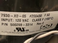
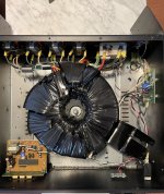
Plitron toroidal part number deciphering

Hi, I have a busted Plitron toroidal transformer in my Furman ri-1220 power conditioner (unit dropped in shipping, ceramic center ring broke). I’m trying to find a replacement, but with Plitron having been acquired by Noratel years ago, figuring out the specs is a real challenge. Can anyone help me decipher?

7930-X0-05 #200430 F:60
Input: 120 VAC CLASS F (155degC)
P/N 500259-3314 Rev.E

Or is there a cross reference Noratel part? (Already emailed Noratel US sales office to ask)

Thanks!
EB

Attachments

  • B451D9F3-1F03-4C36-92FD-D159051B2FB8.jpeg
    B451D9F3-1F03-4C36-92FD-D159051B2FB8.jpeg
    350.9 KB · Views: 87
  • 6507DBDC-2911-4532-A8FE-566CA8F33088.jpeg
    6507DBDC-2911-4532-A8FE-566CA8F33088.jpeg
    681 KB · Views: 90

In search of a Y throat adapter

Hi,

currently I'm converting a 770 transistor Leslie cabinet into a tube powered 160 W one. As I didn't find any mid-range compression driver that could cope with this power, I decided to install two Monacor KU-516's. These drivers feature a 1 3/8" thread. Are there any adapters that allow connecting a pair of them to the rotating Leslie horn? Four bolt flange mounting to the spindle plate would be preferred.

Best regards!

Ampeg 300W SVT. Can I run it on 2 6550 tubes (instead of 6)? With mods.

https://ampeg.com/support/files/Schematics/S Series/SVT (1972, 6550 tube)/SVT 1971 6550 Schematics.pdf

I see two problems...
1. The plates will be running even higher than the already high 695VDC due to less tubes pulling the voltage down. No idea how tubes would fair at say 750+ VDC but probably pushing it.
2. The OT's impedance will be mismatched.

The possible problem solutions I see here are:
1. Plate voltage
a. use a separate power transformer for the plate voltage on the power tubes. This will also mean the bias will need to be different. I have no idea what kind of current the grid bias draw is, but I'd think this could be dealt with by divider resistors being adjusted to alter that voltage.
b. maybe an easier or cheaper solution than a. could the original power transformer be used, but voltage dropped somehow? Maybe a solid state relay with PWM.
c. I have no idea here but one other thought... tube rectifier(s). I seriously doubt there's any tube rectifier that could deal with this kind of power... but maybe one other alternative?? EDIT: forgot about the rectifier heater supplies. Possible maybe, but not at all practical.
2. OT Impedance mismatch
a. change the wiring of the speaker cab to get the impedance up to 3x what it originally calls for since we'd have 1/3 of the tubes and roughly 3x impedance on the output transformer's primary side.

Probably a little crazy to consider this, but it'd have a few advantages:
1. Less cost (and abuse) on the power tubes over the life of the amp.
2. Crank an actual SVT without having to be at crazy power and volume levels.
3. Still owning an SVT that could be put back to stock power later if needed.

400V on triode wired EF86 during startup?

Hi,

I´m about to rebuild an old PC86/6AV5GA SE amp to use more commonly available tubes like EF86 and 6L6GB/C/whatever. The raw B+ is around 400V during startup and I want to replace the messy Mosfet capacitance multiplier in the PSU with a simple choke. Adding an IDH tube rectifier to get delayed B+ is unfortunately not an option.
I'm sure the output tubes can handle 400V without any stress but I'm a little nervous about EF86 in triode connection.
I'm planning to sell the amp so I want it to be quite reliable.

Best regards,
Daniel

Help putting an old tube tester back into service

Hello,

Found a tube tester hidden away and covered with dust, its probably not been touched in 15 years or so when it was moved there and put away. I was really happy to find it because i have a lot of unknown tubes that id like to know if they are good or not.

Is there anything i should be careful of when trying to put it into service again? It seems to be pretty much just a network of switches, with a few resistors and a coupple of caps. Should i do anything more than test the caps and give the switches some electronics cleaner? Can i use it to find "matched sets" somehow?

Here is the model of tester i found: https://www.vintageradio.nl/Diversen/tech_tc2_tube_tester_engels.htm
The schematic is on that website, i am unsure if i could repost it here so ill just link the page.

edit
And what about testing tubes that are not in the manual? Like the 6DJ8/ECC88?

Thanks for any help 😀

V = 2,9*At*R, R and V are unknown

Been sick with influenza, pretty much stuck in bed for eight days, so been researching and attempting to design a BLH subwoofer. Having done so much research, looking at and reading so many pages, I am forgetting where information has come from. Being I have a Macintosh without VMWare and don't want to take time and space for a one time need, doing the calculations by hand; I love mathematics so it is fun. At this point, I am trying to calculate the volume using:

V = 2,9*At*R, where R is the distance where throat area has doubled.

At=(2pi*Fs*Qts*Vas)/c
I found this paper: https://www.passdiy.com/pdf/KleinHorn.pdf. It gives the formula:

Area at x (which I will simplify to Ax)=At*e^(4π*x/λ).

I graduated High School almost 27 years ago, so took me too much time to find how to bring down the exponent, spent an hour solving for x, however, the value is clearly not right. Can someone please help?

My solution for x is as follows:
Ax=At*e^(4π*x/λ).
Divide by At, giving:
Ax/At=e^(4π*x/λ)
According to this: https://www.wtamu.edu/academic/anns/mps/math/mathlab/col_algebra/col_alg_tut45_expeq.htm, we are to take the natural log.
ln(Ax/At)=ln(e)*(4π*x/λ)
But this: https://mathinsight.org/logarithm_basics says to take the log.

Neither resolves the conflict.

Since ln(e) = 1, provides more beautiful and elegant formula, so use that until know which is correct, giving:
ln(Ax/At)=4π*x/λ
Times by λ gives:
x=(ln(Ax/At))λ
Divide by 4π:
x=((ln(Ax/At))*λ)/4π

Since R is the distance x where Ax = 2*At, therefore:
R=((ln(2))*λ)/4π

Therefore
V = 2,9*At((ln(2))*λ)/4π)

Let us use a Faital Pro 12FH500.
At=(2π*Fs*Qts*Vas)/c
=(2(3,14159265359)*45cm*0,0873)/343
=0,07196353784m^2
=719,635378cm^2

Then assume a tune of λ=40Hz, so the wavelength is 858,04cm.

Therefore

V = 2,9*719,635378((ln(2))*858,04)/4π)
V = 98771,9515445cm which is clearly incorrect.

So then where did I mess up, please?

Anyone happen to know the formula for calculating volume?

Thanks in advance! 🙂


PS This is an example of my obsessive personality, I should have been in bed over three and a half hours ago... 🙄

Power limitations for LLC-smps for amplifier

Hi.

I'm a newbie at SMPS and LLC in particular, but with the aid of the app-note An1160 I have managed to get a simple LLC prototype running. I don´t claim to understand every calculation in the PDF, but I put it all into a spreadsheet and it puts out values that are similar to the values calculated in the example.

https://www.infineon.com/dgdl/an-1160.pdf?fileId=5546d462533600a40153559a85df1115

The target is to power a bridged amp with +/-30V driving a single 8Ohm speaker to around 150W (100Vpp).
So peak-current is around 7A, and average is like 1A for music

I'm using a L6599 controller in a standard setup, IRFP450 (overkill, but I had them), and a ATX-transformer-core with a airgap in the center-leg.
Transformer x-section is around 1cm2 and prim-sec windings are side-by-side to integrate all magnetics into one. I have tried dual, triple and littze-wire for primary and although it changed the internal heating a little it does not affect the output power

The LLC works great up until approx 60V into a 22Ohm dummy-load (60^2/22 = 160W).

But when its loaded with 12Ohm (60V/12Ohm = 5A) for just 10mS the voltage drops to around 40-45V and it struggles to maintain soft switching.

Now the ATX-core and the windings will probably never supply 60V@7A for more than short pulses before the heat rises, but it needs to supply the peaks in the sine.

I have tried different resonant-caps and different airgaps. This result in different minimum switch-freq to maintain soft-switching, but it dos not affect maximum output current by much. Also tried to add more sc-windings with little luck.

Depending on the airgap the prim inductance is around 500uH (250uH with shorted sec). Prim-inductance can go from 1500uH to 250uH with airgaps from 0.1 to 1mm with around 50 prim turns.

So, any ideas?

Kind regards TroelsM

For Sale Lazarus Cascade Classic Tube Preamplifier - $629

This is a very cool valve-based preamplifier, with lots of inputs and outputs, all in a low-profile rack-mountable form factor. It uses 12AX7 tubes throughout.

As shown in the photo, it has dedicated Tape, Aux, Phono, CD, Video, Tuner and Phono inputs, with Main and Tape Outputs.

The only odd thing about it is that the standby feature is a bit counter-intuitive, but it all works. Sounds great too!

$629 + freight. Shipped in original carton. Check or money order preferred.

Attachments

  • Lazarus front.PNG
    Lazarus front.PNG
    476.2 KB · Views: 135
  • Lazarus top.PNG
    Lazarus top.PNG
    1,010.3 KB · Views: 141
  • Lazarus rearPNG.PNG
    Lazarus rearPNG.PNG
    622.6 KB · Views: 136

SEAS A26 in oversize cabinet

I ordered the SEAS A26 kit (mid woofer and tweeter) and am about to build the cabinet (aperiodic) which is specified at 28 l. volume.
I'm mostly after the above 80Hz spectrum as the bottom two octaves are taken care of by my distributed bass system.
I've been thinking of increasing the cabinet volume but mostly for the soundstage enlargement sake, not bass.
I will appreciate any thoughts, opinions, advice on this idea.
Real life experience cases also appreciated.

Pro-Ject Phonobox MkII - no sound

This is probably a shot in the dark and/or a vague and unhelpful question but -

I recently got a Pro-Ject phono box to hook up a turntable to my focusrite soundcard and monitors, to listen to and record vinyl.

Bought it second hand (perhaps my first mistake) and it didnt come with a power supply. I tried an adapter I had that said it did a range (15-22v or something IIRC) and the phono box wants 16V so i thought it might work but it didnt. Bought a power supply new that is sold as being correct spec specifically for the preamp, still no signal coming through.

My question is whether i fried it with the first PSU or whether there are any other simple things i might be missing or components to poke inside with a multimeter that might diagnose the issue, dont want to chuck it but not exactly where to start with fixing it, aside from taking it to a repair person.

NB - when its all hooked up, theres a slight pop through the monitors when i plug in or unplug the sound, so there is something getting through, just not my music! 🙁

Any leads most welcome 🙂

High Quality Passive PA Speakers?

My reference speakers used to be Gedlee Summas. I sold them a few years back, they were just too big. Great sound, huge speaker.

A few years later, I bought some Yamaha DXR12s. The DXR 12 is a prosound two-way with a 12" woofer and a very nice waveguide. The Yamaha uses the same compression driver as my Waslo Cosynes. So it's been nice to be able to do A/B comparisons of the two, and get some inkling of how a wooden unity horn compares to a plastic waveguide.

My wife has banished all of these speakers, because they really don't work with the decor in our living room. (The Cosynes are for sale in the swap meet here.)

I've been buried in work for two straight years now, and probably spend 5X less time on DIY than I used to.

So....

Are there any good prosound speakers that are passive?

I came THIS close to buying a set of DXR10s this morning. The cabinet is about half the size as the DXR 12. Compression driver is the same, I think the amp is the same too.

I don't have any real complaints about the SOUND of the Yamahas. But they don't fit in the decor.

If I could find something passive, there are two advantages:

1) I may be able to remove the guts of them and put them into a knock down plywood cabinet from Parts Express, a cabinet that I could veneer and make it look nice.

2) My DXR12s have a nasty hum that's really distracting. Not a huge deal for a nightmare or club, super annoying for a living room. I know that I could run balanced connections instead, but my living room already has a mess of distracting cables and I don't have the time or energy to route everything through the walls.

Teac V-5000 cassette deck's take up spindle (the fwd spindle) stops rotating randomly in the middle of play

Hi,
I purchased this casette deck used on ebay, but in excellent condition. It has this problem.
Cassettes play and record satisfactorily. However I have this annoying problem.
Usually in the middle of play, the take up spindle stops rotating in the middle of the play and then
deck stops playing. I turn off the deck, or even fast fwd or rewind the cassette. Then when pressing play, the playing starts, then shortly after that, the take up spindle stops rotating and the play stops. I don't have a service manual of it, but I have good understanding and technical skills. I am an engineer.
It appears it has 3 motors and 2 belts. I havent opened the case yet. Could this be a worn belt problem, which may be easy to replace,
or more of a logic control issue? Has anyone experienced such thing?
Thank you in advance for any help.
Dinu

Tapped Port Modelling in Hornresp

Hi Folks,

I am intrigued by a few cabinets available for the bass guitar player that are more or less conventional shelf ported designs that have the woofer mounted in the port firing from one side to the other.

One such example is the Bill Fitzmaurice Omni 15. I own one of these and the bottom end is quite spectacular. The port is flared, and the space behind the baffle is completely open (that is to say that its just a reflex box with a flared port and the woofer mounted in the port

1675127889533.png


There are other examples, such as the Boom Bass Cabinets that have a second woofer firing downwards into the slot port.

1675128565675.png


I believe that the two woofers in this box share the same airspace, But for the sake of this post, lets assume the front facing speaker is a sealed back midrange.

How would I model such a beast in Hornresp? I've tried modelling them as a tapped horn but can't seem to get anything approaching a normal looking output.

The BFM Omni 15 is a great box in the low end (it has a pretty undesirable midrange), so I would like to understand how to model these beasts to see if I can tailor them to drivers I own.


Can anybody help?

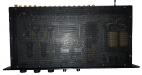
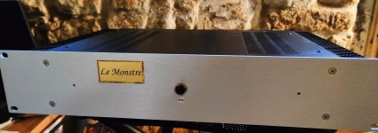
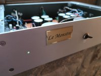
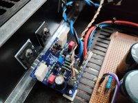
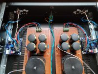
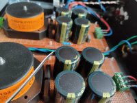
FS: Hiraga LeMonstre clone Class A

Selling in excellent conditions hiraga amp clone. See pictures . Ship to Europe only. 350eur or best offer. Smooth and warm sounding amp in classe A.

Attachments

  • IMG_20221226_113036.jpg
    IMG_20221226_113036.jpg
    203.5 KB · Views: 400
  • IMG20221222132341.jpg
    IMG20221222132341.jpg
    129.6 KB · Views: 422
  • IMG20221222132236.jpg
    IMG20221222132236.jpg
    253.8 KB · Views: 432
  • IMG20221222132308.jpg
    IMG20221222132308.jpg
    367.8 KB · Views: 435
  • IMG20221222132316.jpg
    IMG20221222132316.jpg
    220.7 KB · Views: 392
  • IMG20221222132610.jpg
    IMG20221222132610.jpg
    123.5 KB · Views: 404
  • IMG20221222132215.jpg
    IMG20221222132215.jpg
    234.6 KB · Views: 392
  • IMG20221222132231.jpg
    IMG20221222132231.jpg
    374 KB · Views: 410
  • Like
Reactions: Pano

KEF Reference Model Three Schematic

I am looking to do a complete crossover rebuild for my late 90s Model Three.
Was wondering if anyone has or knows where I can obtain schematics with component values. I want to build a fresh pair of x overs with poly caps, better overall parts quality using point to point ect, Then keep the originals untouched I can put back in if I ever decide to sell. The speakers are the original versions not the three two with boundary compensation.

Thanks in advance.

PCL82 Amp Build

I have been busy building a PCL82 based amp with EM84 dancing indicator valves.

Based on stephe's 6BM8 amp design.

Reusing parts so didn't have the option to ultralinear the output. Nevertheless the result is rather nice sounding, especially combined with a little subwoofer I have rebuilt using a cheap Chinese plate amplifier.

A little cheapie passive tone board provides volume, bass and treble control and seems to operate really well for very little effort 0 money.

Currently using shade feedback resistor of 220k not sure if I should up this given the lack of ultralinear.

Cheers

Attachments

  • IMG_20230120_055549.jpg
    IMG_20230120_055549.jpg
    235.1 KB · Views: 173
  • IMG_20230122_143150.jpg
    IMG_20230122_143150.jpg
    290.2 KB · Views: 168
  • Like
Reactions: Fuling and decramer

For Sale Some nice stuff. HP audio equipment, Semisouth, vFETs

Hi guys. I have reached to end of my diy audio path and I sell some nice things. So, I have one HP3580 in good state, working; one HP 8903B working too. And I offer two nice sets of transistors... four vfet sony 2sk82 tested and one 2sj28 (tested but I have not data when I did it). And I add to batch two 2sk183V. On the other hand, I offer four SJEP120R063 (fantastic for clonning of J2 or F2J).

vfets set ...... 250 eur + shipping + fees
SJEP120R063 ..... 240 eur + shipping + fees
HP3580 ..... 300 eur + shipping + fees
HP8903B ...... 300 eur + shipping + fees

hp1.jpg
hp3.jpg


hp4.jpg


vfet1.jpg


vgs.jpg


SJEP120R063.png

Grounding vintage amplifier to mains

Old vintage 1976(?) Harman Kardon 900+.

Just got done doing a very comprehensive restoration - all the caps, nearly every transistor, etc. Plays wonderfully, but still has a bit of annoying mains hum that comes through the speakers. Not very loud - don't even notice it when music is playing - but it is considerably louder than just about any other vintage gear I have owned.

I can power this thing using my bench supply and it is dead-quiet. I been looking around and it seems these old HK receivers were prone to humming noise.

One guy - who seemed to be a former HK repair tech in the 70's and 80's had mentioned some of this was eliminated by re-routing a ground wire that runs by the tone board - but he has seemingly been offline since before the pandemic (gulp).

Another person (maybe it was here) somewhere had mentioned also having a 900+ that always had a bit of hum when the bottom cover is installed. I do notice the hum slightly more when the cover is on mine, too.

But the real reason for this discussion is: I notice that there is a 2.2M ohm resistor that connects one side of the AC power cord directly to the chassis ground.

For those who do not know... on this particular model, ground is ground is ground. Signal ground, power ground, chassis ground... is all one ground. Also seem to be a couple potential areas for ground loops from what I see and understand of the schematics.

Since the ac plug on this stereo is non-polarized... it seems to reason that the "ground" on this unit could be connected to either side of the AC line (nuetral or hot).

Would there be any harm in removing this 2.2M resistor bridge? If not, you think it is likely to help any of the hum feedback I am getting?

If I unplug this unit while powered on, the humming stops instantly. Keep in mind: it will continue to play music for 3-4 seconds after unplugged due to the large PSU caps. So the hum is certainly coming from the AC line.

Another thought: would it be of any advantage to install a grounded plug on thus unit? Or is connecting chassis ground to earth ground not a good idea?

-Dean

Deoxit???

I'm building a pair of loudspeakers that are intended as heritage cabinets which I hope will outlive me (at least as furniture). I'm paying great attention to crossover assembly, internal wiring, etc., but at some point I'll be sealing up the boxes (although access will still be available by pulling the drivers). I've heard that Deoxit can be helpful in deterring corrosion. I'm not familiar with Deoxit other than as a spray-on contact cleaner...does anyone have any experience with it as a corrosion preventative, and are we talking about Deoxit Gold or something else?
Thanks!
Projects by fanatics, for fanatics
Get answers and advice for everyone wanting to learn the art of audio.
Join the Community
507,608
Members
7,879,379
Messages

Filter

Forum Statistics

Threads
405,834
Messages
7,879,379
Members
507,608
Latest member
HazBuildz4ya