Phono stage ground hum, PSU dependent.

Been experimenting with one of these - https://www.ebay.co.uk/itm/265099568381 - it actually sounds pretty reasonable.

A big part of the appeal was it should work with a wide range of PSUs and doesn't need a dual rail supply, I was hoping to power this and a cheap class D amp off the same PSU - I was thinking a generic 18v laptop supply to keep costs down.

I've found that it's hum free with my bench PSU but that it has a slight hum with the laptop supply. Initially I thought this was power supply noise, but using the laptop supply I tried running a wire from ground on the phono board to the (mains earthed) case of the bench supply - the hum went away.

The turntable I'm using is not earthed to the mains either, so with the laptop supply earth is floating.

Any ideas on how to get this working quietly without a mains earth? I wonder if a similar switch mode power supply with a 3 pin (earthed) mains would behave differently?

Krell KSA 300-S suicide watch

I'm hoping this gets someones attention. I still an unable to get right channel to come on. If anyone been following this fiasco then they don't need a recap, but for thoses who just checked in I will try to bring you up to date. A couple of weeks ago I decided to take my Krell KSA300-s out of a 3 year storage. This has been stored in a climate controlled building. I'm not the original owner, but I had used it for 5-6 years with no problem.
Anyway I got it set up and no right channel. No lights (led's for that side were on). Left side fine. So, I took it apart and found several issues with a previous repair. I fixed those and turned it on again, nothing. I decided to go in deep and found a couple of other problems so I fixed those.
To try and keep down the total times I took this apart I check every active component on that side. The only thing I haven't check were some timer ic's that appear to be used in the auto-bias circuit. Unfortunately the auto-bias circuit is the only thing I don't have a schematic for (and it appears no one else does outside of Krell who appears to be out of business).
I'm in the dark now and asking anyone that might have some insight to this problem to please come forward. I'm very close to putting it to the side and moving on. So, there you go.
I have attached some schematics that would be helpful.
Thanks,
John

Attachments

Order of Operations: Increasing Bass Response in Sealed 2-way Speakers

I have built a pair of towers using vintage drivers I salvaged from beat EPI-400 speakers. They turned out really nice and sound pretty good overall, but bass is a little weak/undefined at lower frequencies. I suspect they could benefit from a little effort at fine tuning them, but I would like to take semi-educated guesses at what might be best to try. Hoping to pick the low hanging fruit first.

Relevant clues that some modifications are necessary:
  • Woofers bounce a at high volume.
  • There is fairly significant cabinet vibration while they're playing.
Some relevant information:
  • These are 6" woofers and they unfortunately do not have any thiele/small information published about them.
  • EPI didn't build any double 6" woofer speakers so I went through some extremely exact math (wink wink) to determine internal volume. I determined the percentage change in volume between a single 8" woofer EPI two-way to a double 8" woofer EPI two-way, and applied the same percentage change to single 6" woofer model from their line-up. End result was a 3600 cu. in. enclosure before bracing, I think ~3400 after. For reference the quadruple 6" woofer EPI-400 these came out of was ~5000 cu. in.
  • The speakers are built out of 3/4" MDF, have internal bracing front-to-back and side-to-side, and are stuffed with fiberglass.
  • The surrounds are original butyl surrounds. They are not that particularly stiff or cracked.
  • Polarity has been double and triple checked
  • I have messed around with placement some as well. They do better against the wall than they did away from the wall (like in the below picture), I've also found they're fairly directional speakers. Bass is definitely improved when you're dead center and near the back wall.
Things I've thought to try, but am not sure which might be most impactful
  • Decrease internal volume
  • Increase quantity of bracing, though would have to get creative with this since their are fully veneered now
  • increase/decrease quantity of stuffing. Amount/compactness of fiberglass is in line with other sealed enclosures I've seen
  • New surrounds
Does anybody have thoughts as to what would be best to try? Thanks!

IMG_3136.jpeg


IMG_3135.jpeg


IMG_3137.jpeg

Re-wiring arm

I believe someone here has rewired his Graham 1.5 arm. I want to do this with my Graham 1.5T. I understand that to gain access to the wiring, heat from a heat gun must be applied to loosen the epoxy sealing the arm. My question is, what areas of the arm are epoxied? I do see epoxy in the area where the leads exit the arm near the cartridge. Is the arm epoxied near the end where the arm attaches to the mounting? Thanks.

Totem Hawk - Need Help Determining the Inductor Value

Hello. Hoping you more-educated &/or experienced folks can help me out with figuring out what inductor value are in these Totem Hawks. They're not marked, so I disconnected them & took a reading with an LCR tester (see pic), but the reading doesn't make sense. The woofer is supposed to be 6 ohms, the crossover frequency is supposed to be 2500Hz, but these numbers just aren't adding up. I'm sure I'm missing something & could use some guidance. Measurement shown. Please & thank you in advance.
pro-RYhLwHAw.jpeg

Strange (?) voltage spike during capacitance multiplier start up

Hi! I have built a MOSFet cap multiplier to filter valve amp B+. Here's the schematic:
Bildschirmfoto 2024-11-13 um 13.23.02.png
Real life DC behaviour on the bench matches the simulation closely.
I have a meter on the load resistor and a meter on the output of the PSU powering it. It is an old unit with an indirectly heated full wave rectifier, so comes up slowly.
The cap multiplier has the typical slow startup from the time it takes for C1 to charge. At the point where that is nearly finished and Vin starts to drop, there is a click sound to be heard from the cap multiplier and Vin jumps up to 1kV for a moment. Unloaded Vout of the psu is 510V, under load 484.
Do any of you have an idea where that spike is coming from and how to suppress it?

Thanks for any useful input.

Speakers for my project

Hi everyone I'm currently in the process of building myself a sound system for my home. I'm currently in the process of choosing what drivers I'm going to use for this build but I'm not entirely sure what drivers to choose.

I plan on having 2 bookshelf speakers for left and right, 2 surround and a subwoofer. For the bookshelf I wasnt sure whether to make a 2 or 3 way speaker. I have already purchased the epique e180he-44 speakers I saw great reviews for this speaker but I'm not to sure what speakers I should pair with this speaker, I've been told the e180he-44 is best in a 2 way but I think a 3 way must be better to achieve better quality of sound and a wider frequency range.

Please could you give me some advice as im pretty new to this I just want some decent drivers to pair with what I have. For the crossover I'm getting one custom made for when bookshelf speakers once they're made.

Thanks

46 driving a 300B

I am in the final stages of building a pair of Monoblock ( LL7903/1:8 to a 46 to a LL1671/30mA to a 300B to LL1664/80mA)
I've got all the PSU dialed in and was reading some of the articles from Ale Moglia of how he switched to the 47 for a bit more gain given his 2v input so wanted to check my gain by the stages.

I have a 4V input from the DAC (SMSL su-10) so the 46 would see ~30V on the grid. I almost went to turn the amp on and realized that the Rk on the 46 is at 17.7V. Should this be 32V ish? should I just do a B- supply to this or do a Rk with a higher value to give me the 32 ish V on the cathode?

Obviously the B+ would have to change to around 240@30mA if using the -30 curve.

With the 4V into the LL7903 in 1:8 it yields the 30V and the mu of the 46 is 5.6 which should translate to 168V swing. The max per the LL1671 on the secondary is 130V rms. Will this configuration drive the 300B too hard and the 1671 too hard as well? I have highly efficient speakers at 96db/w/m so I probably wont be cranking it all the way up anyway but wanted to check everyone's thoughts here.

Attachments

  • SUT_46_IT_300B_OPT.png
    SUT_46_IT_300B_OPT.png
    77.6 KB · Views: 267

2 x Hypex SMPS1200 dead following power cut

We had a power cut last night, once it came back, everything turned on as normal... except my two DIY Hypex monoblocks.

Specifically, both SMPS1200A700 modules have stopped providing any DC power. There is no relay "click", nothing.

- The fuses are fine
- The current inflow thermistors are fine (I had to replace one of these before)
- The main capacitors are charging
- I've tried letting the main capacitors discharge fully before powering on again - no change
- I have checked on other power outlets - no change
- I have tested with and without NCORE modules hooked up

According to the HYPEX data sheet, the SMPS can be latched off if the NCORE module sees a fault, but this should be unlatched after capacitor discharge.

There is also the following in the datasheet, but no more details of how it works:
"The supply is triggered for normal operation or latched off in case of critical fault via in built-in actuators."

Does anyone have any ideas for common faults/diagnosis? The fact they both failed in the same way seems suspicious, and I really don't want to drop >400Eur on two new SMPS if it's just a fault-protection, then wait for the next power cut...

Making a diy USB pre-amp (need help desperately!)

Hello!
I'm still new to audio electronics and learning a lot as I go.

For context, I’m working on building my own USB microphone from scratch as a starting point for more complex personal projects. My current design is inspired by DIY Perks, but I’m designing my own preamp and power supply circuit. I’m working with a tight budget and limited access to specialized or hard-to-find components, so please keep that in mind.

Right now, I'm running into an issue with my power supply section of the circuit.
1731737446148.png


When the power supply is not connected to the rest of the circuit, it provides a stable +15V and -15V output. However, when I connect the preamp to the power supply, the voltage drops drastically to around 1.2-1.8V.

After testing, I discovered that when I directly supply the preamp with ±15V, it works perfectly. This suggests the issue might be related to the Darlington pair circuit.

Blue is micInput, Green is output (Power input connected to pre-amp) Red is output, Green is micInput (Direct ±15V connection)
1731738037185.png
1731738136656.png


Could you help me identify and resolve this problem? If there is anything else, don't be afrain to rag on me for that as well.

Thank you all in advance!

For Sale Tamura A-875 line output transformers

Selling 1x pair of A-875 line output transformers, excellent condition

17K:600 (150 split), 7ma

Originally designed for the 6SN7, but of course can be implemented for any tube that fits the specs, like a 76 for example

Asking 600€, will ship worldwide

Attachments

  • tempImageVZ5S0T.gif
    tempImageVZ5S0T.gif
    1.8 MB · Views: 138
  • tempImagecwIQkd.gif
    tempImagecwIQkd.gif
    1.8 MB · Views: 688

3-way corner speaker?

hey all, in the never ending adventure to both have nice sound and WAF, i'd like to try to build a speaker for corner placement, which will mostly be behind a chair in the corner. This is for mono playback, so there's no second speaker, just one speaker in one corner. I'm currently listening to a linkwitz pluto, but although i like the sound the omni pattern and it works well with mono-playback, it really wants a closer listening position and i don't want to keep dragging the speaker out from the wall every time i want to listen.

The whole thing will use minidsp for crossovers/eq. Primary seating position is about 16 feet away from the corner (see attached poorly drawn room layout). Right now unless the Pluto is close (<9ft away or so), there's too many reflections going on in a bad way (expected but worse than i had envisioned).

so here's what i'm thinking to try to play well with the corner:
highs (>1250hz): B&C DE250-8 compression driver paired with either a HM17-25 or H6512 horn (horn and xover point to be decided upon testing/listening)
mids(300-1250hz): Dynavox LY302F 3.5" tucked right into the corner as close as i can get it
Lows (40-300hz): Dayton RSS210HO 8" woofer

see attached bad sketch of how i would arrange the drivers. view is at a 45deg section of the corner. I neither enjoy nor excel at woodworking, so i was hoping to just use the denovo knockdown cabinet for the 8" woofer. so all i'd have to build is a simple box to house the midrange. Unclear right now if i'd just mount the midrange box onto the wall, or have legs that go down to the woofer box.

I've seen Wayne's PI corner speakers and if i had the space i might just buy that. but they too big to pass the WAF test.

all thoughts, comments, criticisms, better ideas welcome! Thanks!!!!

Attachments

  • CrossSection.JPG
    CrossSection.JPG
    240.8 KB · Views: 139
  • Room.JPG
    Room.JPG
    258.4 KB · Views: 139

Theta DS Pro Basic 3 DAC blows a fuse

Hi,
Don't think I am a DIY person because I am a member here 🙂 I can do "some" stuff but not too much 🙂

So, I bought this DAC from someone knowing it was not powering up. The seller said he had no time to check and I took my chances thinking it could be an easy fix such as a bad fuse. I was like you know what I had a unit with an issue before and a fuse replacement solved the problem. Maybe this will be the same.

I put the appropriate fuse I hope because that's what it had in it, slow blow 3/8A (375mA).

WELL, THE UNIT POWERED UP, I pushed the buttons, they were all working, etc. two minutes later, I saw the fuse burned like red and then puff! The unit back to dead again 🙂

What could be the reason for working few minutes and then burn a fuse?

I have a friend who has all the tools to fix it (if fixable) but I thought let me ask here maybe it would help him pinpoint the problem.

Sales on Klein tools

For those of you in the US needing to add hand tools to your kit, I've been seeing a bunch of sales on Klein tools. Diagonals/linemans/wire stripper combo for $50 is a relative steal. There are other deals worth exploring as well. The big Milwaukee push to ride the Red Fan-boy wave, offering an ever increasing product line, plus the fact that quite a few tradesmen have been gravitating toward Knipex/Wiha/Wera tools, has apparently had a significant impact on the old guard.
That said, after decades of using Klein HT almost exclusively, I'm trying some Knipex pliers/Wiha screwdrivers and I'm impressed.
In any case, its a good time to snag a deal if you're in need. HTH somebody.
Cheers

Looking for additional counterweight for Akai AP001c tonearm

I have mounted the tonearm of an Akai AP-001 on my turntable. I placed a cartridge and headshell on the tonearm which are so heavy that the tonearm weight is almost at the end of the tonearm for the correct tracking weight. I read on a Lenco forum that Akai sold a separate additional weight for this (and similar) tonearms, encircled on this image. Does anybody happen to have this additional weight?

Help - Practical Speaker Building Tips / Advice required

Hi,

I plan on building Troels Gravesen “The Loudspeaker 3” to replace my Audio Technology 3WC sometime in the new year. Its an itch I need to scratch.

I have limited woodworking / soldering skills (practical skills in general!) and would really appreciate if any of you could share any useful tips with me.

My intention is to use either 21mm or 24mm birch ply and get the panel sizes cut to size with the driver holes CNC routered out by others and assemble the cabinets myself. I plan on staining the finish side of the panels before assembling (as Troels practices) and use a peg board to cable tie the crossover components to.

I’ve seen these square clamps to achieve the right angles are they suitable, or are there better versions to use?
https://www.ebay.co.uk/itm/39526735...=2047675&ssuid=&widget_ver=artemis&media=COPY

My existing speakers I have lined the inside with 5mm (10kg) barrier shield product and plan on doing the same again as I immediately noticed that the speaker / cabinet sounded quieter. Website with date sheet is: https://www.cmsdanskin.co.uk/indust...c-material-for-industrial-use-type-wb-epdmbs/

I was then going to use 25mm self-adhesive foam sound insulation to create a poor mans version of “No Rez”……do you think that would be beneficial?
https://www.ebay.co.uk/itm/14129530...ar=440412235067&widget_ver=artemis&media=COPY

I also found it hugely beneficial to stuff the cabinets with rockwool, so I plan to compare this to the wool roll included in the kit..

For the horn itself, I have read about people dampening the insider face of this, I was thinking of using a 2 / 3mm bitumen sheet and then using the 25mm foam insulation on top…..Is this a good idea?

I would appreciate any soldering tips….what is your opinion on using spade connectors for the drive unit connection? I remember trying to solder the speaker cable to the drive unit connectors and the pull from the magnets was insane, it did pull the iron towards the magnet a few times tbh and I struggled holding the wire still while the solder set….

Under my existing speakers, I am using industrial springs to isolate the speaker from the stand and was planning on doing the same again by using two steel flat plates, front and back that span across the speaker and go out the sides…
https://www.christiegrey.com/industrial/enclosed-spring-mountings/

I would really appreciate your thought and advice so this build can hopefully be a bit better than the last. Thank you

LinearX LMS 4.X - Complete Software Setup

Hello everybody.
I am looking for the complete software for LinearX Lms, version 4.6, alternatively also 4.1 or 4.0 or even all versions.
The update setup on the physical Lab site does not work for my version.
I currently have the Dos, Linearx Lms 3.5 version only.
Please, I ask you for support.

My email is:

martincastrovincisystems@gmail.com

Thanks for helping me.

KRELL KAV280cd - with issues need help

Hello,

My KRELL KAV280cd is faulty !
The problem :
- digital outputs, coax & optics are OK,
- analog outputs, coax & XLR, left & right are wholly
dead.

Power supply is OK : +/-18v +/-5v ...
Then, I suspect one issue on :
- digital filter board,
- or on DAC board

My problem, for understanding and repair :
- I have no schematics, no sm
Truly, I would appreciate if you could help me

Raymond
( pardon my English ! )

KRELL KAV280cd - face capot démonté (R).jpg

KRELL KAV280cd - bloc décodeur - audio outputs (R).jpg

Sansui BA-2000. Where is the air?

I have a Sanusi BA-2000 that I like a lot that I have recapped and refurbished a bit but to me there is a perceivable lack high frequency content compared to other amps. It seems like this is a consensus among other owners. The stated specs say otherwise and that it's response is pretty much flat in the audio band. I was hoping to dive into the circuit a bit to try and find what part of the design could be affecting this. My initial thought is that there are some frequency / phase compensation circuits affecting this and perhaps they could be modified.

On the driver board, I'm looking at (guessing!) C03 is (33pf) is part of a low pass filter (maybe this value could be lowered to 22pf). C29 and 31 as miller compensation and C33 and C19 as low pass filter and compensation. Can adjusting the miller compensation caps have an effect in the audible spectrum? Also, could I lower the value of c33 and bleed off less high end? There also is a capacitor C55 that appears to be hanging off the feedback path as well.

I'm just taking wild guesses here so if there's any way to get to the bottom of why this amp seems to sound a bit dull and ways to change that, I'm all ears.

Tannoy LSU Gold 15/8

Hi,
I lately got a pair of 15" gold but without the original crossover. The autoformers which were used in the crossovers are not easy to reach. I think the autoformers can be substituted with a fixed coil inductor. I therefore would like to ask if any member has done one before with this same situation. Or any recommendations/ comments are welcome.
Regards
Albert

Musical Fidelity X DAC - very low output

Hello!

I have just got my hands on one of the old school cylindrical MF X DACs. It seems to lock on to any signal I plug into it from either a CD/Sonos/TV but the output is extremely low and a little distorted. I've tried coax, optical on all the above sources and on 2 different systems and the issue is the same every time. Any ideas what ,might be causing this or how I could resolve?

Thank you.

Looking for datasheet Sony CXD1125Q/1130Q/1135Q

Good morning folks,

I am resuming my cd player retromod project after some time away from it. Being snowed in doesn't leave you with much to do. I have hit kind of a dead end though. I need a datasheet for the Sony CXD1135Q. It would be bundled with the 1125Q and 1130Q. The datasheet I have been able to find online is only 6 pages, and I am needing the section that talks about how it operates (commands, timing), not just pinouts. My search keeps leading back to some posts on the diyAudio forum that mention a more complete version available, around 37 pages or more for these DSPs. The last page of the 6 page version indicates at least 260 pages. Really, I am just looking for the detailed info on the 1135Q, its commands and timing stuff. The links posted on this forum that lead to vasiltek.nm.ru aren't working for me.

I would greatly appreciate some help tracking this down. Stay warm folks!

Kenwood KAC-PS401m stuck in protection

Hi I have a KAC PS401m on the bench stuck in protection mode flashing also low battery led on.

The crossover board had the usual corrosion from sticky fibre tape, I've removed the tape, cleaned up the corroded traces and pads, re run the solder and tested the traces for continuity also replaced the capacitors on the board and its made no difference, the relays don't click on and the aforementioned remained flashing/on.

Any ideas on what to check next would be appreciated.

Attachments

  • IMG_20241114_174323.jpg
    IMG_20241114_174323.jpg
    375.1 KB · Views: 94
  • IMG_20241114_174329.jpg
    IMG_20241114_174329.jpg
    225.2 KB · Views: 54
  • IMG_20241114_174330.jpg
    IMG_20241114_174330.jpg
    193 KB · Views: 54
  • IMG_20241114_174332.jpg
    IMG_20241114_174332.jpg
    183.2 KB · Views: 50
  • IMG_20241114_174334.jpg
    IMG_20241114_174334.jpg
    243.8 KB · Views: 71
  • IMG_20241114_174336.jpg
    IMG_20241114_174336.jpg
    262.4 KB · Views: 59
  • IMG_20241114_174338.jpg
    IMG_20241114_174338.jpg
    336.5 KB · Views: 60

Alpine MRD-M605 class D switching issues

Hi

Long story short, amp turns on but produces gibberish at it's output. No shorted, burnt, damaged stuff.

Quick check did not find any missing or out of tolerance auxiliary or main supply voltages. All seems fine. No heating.

I've checked the class D switching frequency , one of the drivers (IR2010) is switching at 120khz but the other one at 330khz. Shouldn't they produce the same ? Shape is also a bit odd for the 120khz.
The inputs to the drivers (HIN and LIN) are inline with the output(LO and HO), so 120khz comes in 120khz comes out, so I suppose it's not the ICs...it is doing what it's being told to do so.

I do have a service manual but it's for the bigger brother from the same series Alpine MRD-M1005, so i've used that as a reference. I'm trying to understand what is setting the switching frequency input to the driver and why it is so much different.

Attachments

  • 1.jpg
    1.jpg
    886.3 KB · Views: 60
  • 2.jpg
    2.jpg
    526.5 KB · Views: 78
  • 1731685624960.png
    1731685624960.png
    330.7 KB · Views: 50

Equalizer vs. Electronic Crossover

It’s common to find any installations placed the electronic (or active) crossover after preamplifier (and before power amplifier), in both home and car audio. While the equalizer is usually found to be placed in “tape monitor” loop or before the preamplifier.

What’s the reason for those installations? What will happen if the EQ is placed after preamplifier and the crossover is placed before the preamplifier?

GDT Proportional winding?

Hi, i am building a 350w +/-60v isolated SMPS. I recently finished a succesfull DC-DC converter, so this is my first time using a gate drive transformer to isolate the switching circuitry from the half bridge.
My first prototype (input rectifier and output caps + inductor on seperate board, no heatsinks yet):
IMG_1176.jpeg


The unregulated smps i have built is working pretty nice so far however i would love any improvements and suggestions with the circuit, but also i am a little stuck on what to do with the "proportional drive winding", that i will explain.

Capture.PNG

Highlighted in red from pins 5-2 of the GDT, is what i will call the "proportional winding" though this is probably the wrong terminology. Follow it along and you see that this winding going through the gdt actually links the main transformer(U1) to the half bridge! The reason for this winding through the GDT is to help the SMPS startup, by providing a little bump on one of the GDT gate drive secondaries, which is enough to start up the auxilary winding on U1 for the tl494, which quickly takes control over GDT.
I belive the "proportional winding" is also to help supply a bit of extra current to the GDT's secondaries to provide a little extra gate drive current.
The problem is, im not sure how many windings i should do for the proportional winding. Unfortuanately, this GDT transformer i bought has no data sheet, so i am unaware of how many windings there are for its gate drive secondaries. I had to hand wind the proportional winding onto the GDT, and at the moment i am using 3 turns. I could vary the number of proportional winding turns and take osc measurements, but i dont know what GDT output i should be aiming for.

GDT secondary drive winding oscilloscope measuement without any current flowing through the proportional winding (TL494 externally suplied):
IMG_1168 Copy.jpeg

GDT secondary drive winding osc measurement with the SMPS fully on, current flowing through U1 and proportional winding:
IMG_1167 Copy.jpeg

Drive circuitry on primary side of GDT, if of any help:
1730999608929.png

Focal Aria cross over upgrade and listening experience

Was it worth it? Oh yeah! Loved the 906‘s 99% of the time. Female vocals like out Adele could be too sharp.

Is there anyone else who has tackled an Aria crossover upgrade?

My impression listening side by side with one speaker upgraded is that vocals are presented differently;
- There is additional texture, layering and separation
- Rather than voices sounding 6 inches in front of the speaker, there is now depth around the speaker
- Adele‘s loud passages are still powerful but not quite as sharp or shouty
- increase in dynamic range and extended high frequency. Initially noticed with background vocals on Louis Armstrong Saints, which was my first test track

If you have taken a similar journey, please share your experience. Here are before and after photos …

Attachments

  • 705A01CA-F778-40FA-A53B-7668FC05C610.jpeg
    705A01CA-F778-40FA-A53B-7668FC05C610.jpeg
    494.7 KB · Views: 582
  • 1CECD558-6422-4874-80A2-A546B52B5BDA.jpeg
    1CECD558-6422-4874-80A2-A546B52B5BDA.jpeg
    374.5 KB · Views: 530

For Sale SA2015 (stereo kit)

SA2015 V-MOSFET (100W@8R, 200W@4R)
2x SA2015 PCB
2pair IXYS IXTH80N20L + IXTH48P20P
2pair 2SC4793 + 2SA1837
4pcs KSC3503
2pcs KSA1381
small bc550, bc560 matched (Vbe + Hfe)

I require 30€ + shipping, preferably in the EU

Payment: PayPal

Attachments

  • sa2015_v_mosfet_ixys_single_schematic.png
    sa2015_v_mosfet_ixys_single_schematic.png
    149.9 KB · Views: 343
  • sa2015_ccc.jpg
    sa2015_ccc.jpg
    701.4 KB · Views: 83

They don't make them like this anymore...

This +40 years old Merc W123 did survive 4 days in a flooded garage in the big floodings in Valencia, Spain.

The newsrports says that it started at first try. I don't know if that is true, but it did start and drive itself out of the garage, covered in mud.

Login to view embedded media
I see no modern car do that. And even most oldeer cars won't do it neighter. Even Mercedes doesn't do this anymore. Those old ones were complete overbuild and as reliable as can be. But sadly that is not the case anymore...
  • Like
Reactions: stv

Biasing a creek 6060, bias is very low at factory settings of pots?

Hi gang,

I am working on an old Creek 6060 integrated that I got that was not in great condition. Dirty etc.. just from age mostly. It was in working condition when I got it.

I did a full recap and it needed protection relays along with a bunch of bad solder joints. The amp seems to work fine and I've put a bunch of hours on it with no issues. I am revisiting the biasing of this amp because it's the only thing I didn't really dig into, assuming it was most likely fine. What I am finding is that the bias is very low, I can adjust it up but I am a bit concerned I may need to look elsewhere in the amp before I just go cranking up the bias values.

The inside of the amp says bias to 20ma, I have .22 ohm emitters so the math says I should have about .044 across those resistors. I had more like .004 which seemed a bit strange given I hadn't touched the pots. It also runs pretty much ice cold no matter how long its been on.

Should I be looking elsewhere before turning up the juice on this thing? I guess that's the real question I have.

Thank you!

How to diagnose scratchy noise at tweeter in an inverted LM3886?

Hi,
In 2022, I've built an inverted LM3886 kit from aliexpress. It had stability issues and fried resistors in Zobel network before but I've resolved it (it was the missing feedback loop capacitor C3,C4). I noticed that absolute value of the gain/ feedback capacitor is a little high (220k/ 7.5k) but I left them as is.

I haven't use it much until recently I've moved to my new place and got a new pair of speaker (Wharfedale Diamond 12.1) and use the set as desktop setup. The amp is quiet and perform well, but occasionally, it distorts at tweeter of the speakers, it sounds like "scratchy" on some notes. It is louder on right channel than left channel. The problems goes away when I turn it off and turn it on again. This problem is so random, but if it exhibits the distortion on some part of the song, I can consistently try to play that part of the song to repeat the problem (I have a list of problematic songs).

Please suggest what procedure should I taken to diagnose this. I don't have oscilloscope but plan to get a handheld one soon. Here's the schematic of the amp.

Thank you,
AP


1725248199115.png


1725248772609.png

Faulty but self-healing class-D?

I've got a crown XLS 1002 class-D amplifier, the little brother of the 1502 reviewed and pictured by ASR here
index.php

It was a second-hand bargain for which I don't know the history other than it has been stored in my living room for the last couple of months (i.e. it is not cold or damp). When I tested it, it initially seemed fine but after a while noise started appearing on one chanel only - not a hum or hiss, instead it sounded very like a microphone being gently buffetted by an intermittent blustery breeze. Choice of input or no input or (IIRC) gain knob position made no difference at all.

I know very little about class-D circuits, and these days I have almost no electronic testing facilities either. So had more or less decided to take out the electronics and just use the rack case for an end-point/renderer; it wasn't a very expensive amp, so is probably only worth so much tinkering. But... I left it powered up for several hours and the issue seems to have gradually cured itself! I don't have much chance of tracing it whilst it isn't there, which leaves me in limbo as to deciding what to do with the thing. I'm aware of electrolytic capacitors having some ability to self heal (though none look outwardly dodgy) but I have no idea if there might be other possibilities.

The best idea I currently have is to point a fan-heater at it, and 'if' that causes the issue to re-emerge then try a freeze-spray on selected components. If not then I'll probably just abandon it and get a replacement; this was to be used (for the 300hz-to-1000hz drivers) in a pair of multiple entry horns, which are going to be costly and complicated enough that I could do without possible artefacts or unreliability (or potentially even damage) from one of the amps.

But before I decide, I just wondered if anyone has any more sensible or informed thoughts on the possible cause or resolution?
Thanks,
Kev

Measurements on output transformers for the Williamson amp

I recently did some measurements on three contemporary output transformers aimed for use in the Williamson amp.

The measurements provide a look at the primary winding inductance, as well as impedance and output frequency response over a 2Hz to 95kHz range (the limit of my USB soundcard) using REW software.

The output transformers were the venerable Partridge WWFB, plus two Australian made OPTs that came out in early 1948 to meet the Williamson diy demand (Ferguson OP25 and Red Line AF8).
https://www.dalmura.com.au/static/Partridge%20datasheets.pdf
https://www.dalmura.com.au/static/FergusonFeb1948.pdf
https://www.dalmura.com.au/static/Pages%20from%20Australasian-Radio-World-1948-06.pdf

The measurements are not for the OPT in a Williamson amp, but just of the OPT itself, but do provide an insight in to how a particular OPT could be compared to other OPT's, and to support how such an OPT could be integrated in to a Williamson amp and the required low and high frequency response tailoring that may be needed for unconditional stability.

Aspects that I thought were quite interesting were the noticeable response differences when choosing a speaker impedance setting, and the variation of measured inductance due to a variety of influences.

The write-up is linked below, and may change over time if I come across other contemporary OPT's or add to the measurements made or correct mistakes/misunderstandings. I must admit that the 'modern' soundcard/REW combination is a joy to use on a diy bench, and can but wait and hope for a new generation of soundcards that bring sub-1Hz to circa 190kHz bandwidth capability, as that would provide a nice addition to an OPT's performance assessment.
https://www.dalmura.com.au/static/Williamson%20output%20transformer%20measurements.pdf

For Sale Jeff Young HPA1 (board + original parts)

1x HPA board
2x 10uF Mcap Mundorf
2x 1uF Mcap Mundorf
1x 2SB1257 - the part is unavailable in official stores
1x 2SD2014 - the part is unavailable in official stores
2x FQP3P20 - the part is unavailable in official stores
2x FQP3N30 - the part is unavailable in official stores
2SK170/2SJ74 - matched quad (8 - 11 mA)

I sell only together! All parts are of guaranteed origin.

Price is 150€ + shipping. Please PM.

Attachments

  • IMG_20240930_074927.jpg
    IMG_20240930_074927.jpg
    399.9 KB · Views: 136
  • IMG_20240930_074954.jpg
    IMG_20240930_074954.jpg
    355.4 KB · Views: 167
  • IMG_20240930_075014.jpg
    IMG_20240930_075014.jpg
    424.5 KB · Views: 174
  • IMG_20240930_081642.jpg
    IMG_20240930_081642.jpg
    340.4 KB · Views: 167
  • IMG_20240930_081652.jpg
    IMG_20240930_081652.jpg
    430.8 KB · Views: 138
  • IMG_20240930_082114.jpg
    IMG_20240930_082114.jpg
    460.4 KB · Views: 131
  • IMG_20240930_082212.jpg
    IMG_20240930_082212.jpg
    343.1 KB · Views: 127

Light bulb current limiter or another alternative

I am in the process of of repairing my Parasound JC1 amplifier. I have built a light bulb current limiter cable and tried it on my good amp (at least it is used to be). When I turn on the amp the inrush current is making the bulb light up but the protection board relay is triggering off/on cycle that repeats over and over. The caps do not get a chance to charge up. I am using 100W incandecent bulb (highest wattage I have available). I suspected it would not work for this amp but I haven't powered on the good amp in a while (not sure if it is still functional).
What would be my other alternative? I do not have variac. I believe we have Chroma in the office that can generate various AC mains voltages and shapes. Should I try using it and set the voltage lower than 120V? Any suggestions?

Hello, and thank you for accepting me!

My name is Dan and I’ve always been interested in audio equipment. Mainly car audio. Electronics has always been an interest of mine and I’ve had a lot of luck mostly just throwing a bunch of parts at amplifiers to get them functioning. I would love to gain the knowledge to be able to pinpoint faulty components, to find the smoking I guess you could say. I am physically disabled after a car crash and have some spare time on my hands. I’d love to learn more about components, scopes and testing procedures. Just reading through some of your posts has given me new insights. Anyway I really appreciate you guys letting me be a fly on the wall. Thanks!
  • Like
Reactions: birdbox

Tubelab SSE sudden excessive B+ voltage

Hi everyone,
I built a Tubelab SSE about a month ago (first amp built ever) and have been really enjoying it.
I've been experimenting with different tubes, trying KT88s and EL34s (I prefer the sound of KT88s so far), and I've also tried different input tubes.
The amp has been running for 4 hours a day during the week and much more during the weekends.

Then one day, I turned on the amp and noticed that the tubes were glowing brighter than usual
I checked the B+ voltage at the end of R4, which normally reads around 440V. However, this time, the multimeter kept climbing way above 500V, and eventually maxed out 😱
I turned off the amp, and after a few seconds, the voltage started dropping from 500V to nearly 0.

Suspecting a faulty JJ rectifier tube (they have a reputation for reliability issues), I replaced it with a new Sovtek tube, but the problem persists.
I've also carefully checked for bad solder joints and loose connections, but everything seems to be fine.

The amp is currently configured in triode mode without CFB or ultra-linear feedback.
Here are the specifications:
Output Transformers: Hashimoto HC-507U (using the 4-ohm output)
Power Transformer: Hashimoto PT-165R
Choke: Hashimoto CC-10-200W
Tube rectification only (no D1 & D2)
Coupling capacitors: 0.22uF
Supplemental capacitor: 47uF + 47uF

Does anyone have any idea why I'm suddenly getting such high voltage readings?
Are there any specific components I should check?
Thanks for your help

Attachments

  • PXL_20241110_144906912.jpg
    PXL_20241110_144906912.jpg
    659.4 KB · Views: 111

Help with coaxial speaker choice for iBigBoy (yup)

Hello all.

I have a thumping great Fidek/Azatom iBigboy 2AD BTX ICD that I use outside. It's heavy, loud and has phenominal bass. I love it but I've blown one of the speakers and need to replace it. Information about the device is sparse and tech help non-existent, so I've come here in the hope that someone can help me match the speaker to the device.

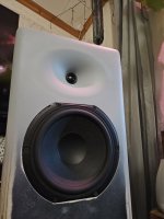
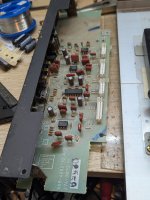
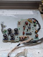
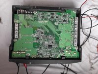
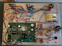
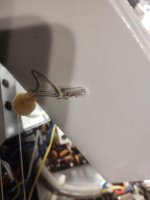
The audio section includes a Class D Yamaha amp with a 10" woofer and two 5" coaxial speakers. I have blown the tweeter in one of the coaxials so am trying to replace both of them with 5" or 6" coaxials of a similar power rating and quality (or better). But I have no idea what spec they are and no way of finding out.

These are all the specs given for the iBigBoy in the manual:
OUTPUT POWER :
UR CH (Nominal): 30W+30W THD = 1% 8 ohm
SW CH (Nominal): 64W THD = 1% 4 ohm
RMS: 240W. PEAK: 500W
FREQUENCY RESPONSE:
UR CH (200Hz-20KHz at +1 I -2dB)
SW (40Hz-200Hz at +4/-13dB)
SENSITIVITY:
UR:550mV SW:200mV
OVERLOAD SOURCE e.m.f.: >2V
SEPARATION: >55dB
S/N: >70dB

Less authoritative info I've found (so not too sure whether to believe it or not) includes:
Impedence: L/R: 4 ohm, Sub: 4 ohm
Sensitivity: 90dB +/- 3 dB
Frequency Response: L/R: 200 - 20Hz, Subwooder: 20 - 200Hz

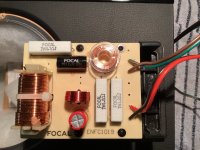
The existing speakers do not include a crossover and have four wires (two for main speaker, two for integrated tweeter). I assume the speakers are 'full range' with the 200hz and below filtered off to the 10" bass speaker via another crossover.

So my question is: what power rating and impedence should the replacement coaxial speakers be to get the best and loudest sound out of this beast? (I can adjust the holes in the cabinet as required.)

So far, all I've found are these but have no real idea if they'll do the job (I'm guessing not):
nominal impedance of 4 ohms, a frequency response of 36-20,000 Hz, a sensitivity of 90 dB, and a rated power handling of 40 watts.
https://www.soundimports.eu/en/sb-acoustics-sb16pfcr25-4-coax.html

Thanks for any help with this.

iBigBoy - 250px.jpg

Kenwood Receiver KR4140 Bulbs

Hi
Im looking for a UK supplier who can provide me with replacement facia bulbs (8v 03a) I need three which are the clear fuse looking type (28mm x 6mm).
I also need a small bulb I think they are called wheatear in the US? no idea of spec but its the light which illuminates the STEREO text for FM signal, See Pic.
Hope someone knows of a supplier.
Ta

Attachments

  • IMG_20241114_171313957.jpg
    IMG_20241114_171313957.jpg
    150.9 KB · Views: 53

SS15 or a different home for my 3015LF?

Retired wedding DJ here. I sold my main system, EV Tour X 12" tops and 18" subs but kept my powered EV Live X ELX112P speakers for small events here and there. I don't use them frequently, but when I do I would like to fill in the low end with a sub(s). Along came the Parts Express catalog a few months ago, the DIY speaker builder edition, and I got the itch to build a sub. I've never built a speaker before and it sounds like fun.

I got all excited reading through the very lengthy Single sheet TH challenge thread and placed an order for an Eminence 3015LF witht the intent to build the JBell SS15. I got in on the 10% off sale at Loudspeakers Plus, although I would have rather paid 2010-2011 prices that were listed early in the thread! I have the plywood and am ready to start sawing, but I recently found this thread talking about a T-TQWP design:

I like the form factor of the T-TQWP. I think my EV's would sit on the top nicely like Dons Peaveys in his post #36. I also like that the box looks easier to build. I am not an expert wood worker by any means, but I do have the appropriate tools and I don't think I would have any trouble with the SS15, but the easier the better for my first build.

I see that the T-TQWP will play lower at the expense of losing 3dB. Don mentions in post #36 that it was a high price to pay for the lower frequency response. Maximum output isnt my main goal, but of course I do want all I can get out of it just in case I end up in a place where I need it. My questions is, will I feel cheated on output by going with the T-TQWP design? I would be mostly playing country, rock and pop music for small wedding receptions and other random, small, indoor events. Mostly at moderate levels, but would like the ability to get loud if the gig calls for it.

Which one would you choose?

Creating own headphones

Hello,

So I am here for simple reason I wanna make own brand. Recently I figured that my country only runs on idea "buy cheap, sell high" business model, and eventually I figured why not try making something own, I wanted to do that anyway, and later I figured earphones or headphones seems doable.

And I am here, I made own first very early prototype to get an idea what's up.
Ran into interesting problem, that there is not really PCB's in the marked that offer reasonable quality, most PCB are general purpose. Or I am wrong here? And I am currently trying to learning/making own PCB on KiCad.

So that my little introduction, so again hi.

Maybe someone feels like giving me insight or own idea or experience?

HiFiCompass PuriBliss-4P25B kit

Dear forum members,

@HiFiCompass and I are delighted to present this remarkable speaker kit for your consideration: PuriBliss-4p25b. State-of-the-art drivers, comprehensive measurements, meticulous design, and numerous hours of listening have culminated in these compact yet incredibly impressive sounding speakers. We welcome you to follow the link and explore the description and find additional details on how to place an order: https://hificompass.com/en/content/puribliss-4p25bii-diy-kit
Projects by fanatics, for fanatics
Get answers and advice for everyone wanting to learn the art of audio.
Join the Community
507,774
Members
7,888,134
Messages

Filter

Forum Statistics

Threads
406,221
Messages
7,888,134
Members
507,774
Latest member
pete2000