Does anyone recognize this tube amplfier?

I have been trying to determine what brand this amplifier is. My parents bought it for me (used) in the middle early 70's. It was my first guitar amp. I have it on my bench now for some repairs, as it has been relegated to a closet at my parents house since before time began. It had quit at one point, and it was replaced with a Peavey.

My dad is quite elderly now, and I was going thru one of the closets preparing for the inevitable and ran across my old amp and one of my grandfathers (an old Silvertone 1472).

I have looked all over this amp, no markings, no label no clues. It appears Japanese made as all the tubes but one are "Ten" tubes, which I believe is Japanese. It appeared to have a logo on it at one point, as there is a screw thru the grill cloth in the upper right corner. I never recall a name being there.

I have the amp playing now after replacing a couple of blown capacitors. I still have some fine tuning and cleaning to do, but it does have a nice sound, the tremelo effect is interesting, but the volume has to be completely parked at what should be low/no volume and then it seems to set the amp at a certain volume and the tremelo effects/controls function. I will explore that later today when I fully inspect the volume pot to see how it is designed. The speaker is a 10 in. 10 watt.

I have attached some pics, the one of the back is with the cover board off (would cover about 1/3 down from top. One is of the top control panel both installed and another pic out of the cabinet.

Thoughts anyone?

Attachments

  • 20241108_105848.jpg
    20241108_105848.jpg
    1.1 MB · Views: 158
  • 20241027_181146.jpg
    20241027_181146.jpg
    736.6 KB · Views: 155
  • 20241107_175859.jpg
    20241107_175859.jpg
    741.5 KB · Views: 164
  • 20241107_181454.jpg
    20241107_181454.jpg
    773.1 KB · Views: 151

Philips CD-960 tray won’t eject help!

Hi all I recently got a Philips cd 960 in lovely condition unfortunately it’s not working

The tray will not eject when pressing the button however it closes when you manually open it and press the close button

It doesn’t play CDs however when the cd is seated it spins for a few short seconds and then stops

I have replaced the 4 belts with the nanocamp kit carefully and lubricated the shafts and motors when I press the open button I don’t even feel the two spindles with the wire try to move to support it opening

I used the drive wheel space to minimise movement when replacing the belts

Any ideas where I can look next to get this cd play up and running?

Attachments

  • IMG_3026.jpeg
    IMG_3026.jpeg
    368.1 KB · Views: 154
  • IMG_3024.jpeg
    IMG_3024.jpeg
    314 KB · Views: 143
  • IMG_3021.jpeg
    IMG_3021.jpeg
    395.7 KB · Views: 137
  • IMG_3022.jpeg
    IMG_3022.jpeg
    431.5 KB · Views: 146

For Sale Allo Kali I2S reclocker

Allo Kali I2S reclocker for use on a Raspberry Pi or Sparky. New nowadays €99, bought from Audiophonics on February 9, 2021. Asking price €69 60 excluding shipping from The Netherlands.

This is the 22/24 MHz version up to 192 kHz, which offers lower phase noise than the 44/48 MHz version which goes to 384 kHz. Oscillators are of NDK make.

As good as new, where I've soldered power wires directly to the board. I used it isolated from the RPi beneath it for as little noise as possible. It's also possible to feed it 5V from the RPi itself. To do so, just close the SBC jumper (which is now open).

Manuals: https://www.allo.com/sparky-eu/kali-reclocker.html#downloads

tempImagepjNr9f.gif


tempImage4erdtP.gif


I used this HAT as extra reclocker before my Soekris dam1121-01 (see my other listing). Even though though the Soekris does reclocking itself, placing this femto reclocker before the DAC made for a significant improvement in sound quality. I was sceptical before, but the improvement was noticeable immediately.

Relay Attenuator for my XA252

I really don't like having to reach around the back of my amps to turn them on, this was a big incentive to design this.
Teensy 4.1 Relay Attenuator.pngTeensy 4.1 Relay AttenuatorB.png
A 256 step relay attenuator with 0.5dB steps controlled by a touchscreen and IR remote. A Teensy 4.1 micro control unit is used to control everything, I have been playing about with this for a couple years trying to develop a really good intuitive user interface. The board was going to use a PGA2310 to do the attenuating but last week decided to use a stepped relay attenuator. The PCB ended up at 200mm x 130mm, I managed to fit 2 PSU's, 2 buffers, 2 Amyalice filters for the buffers, 230vac 15A relay for a power amp, and a relay for speaker grounding (anti-thump). It has 5 inputs, 2 outputs that will accept SE or DIFF in or out.
IMG_8021.jpgIMG_8022.jpgIMG_8023.jpgIMG_8035.jpgIMG_8027.jpg
The ILI9342 is a 2.8" touchscreen display and it is really hard to take photos of it. You can change the colour of all the different elements on the screen and uses BrunoSans font. For the large gain numbers I had to edit it the font to make it work, the numbers were different widths which look good if they are static but when changing looked weird. You can also rotate the screen, adjust the brightness, adjust the backlight and calibrate the touchscreen.
IMG_8026.jpg
The input names can be changed, I have a list of over 20 to choose from. An inputs gain can be fixed so it will work well with an input with its own volume control like a TV or computer. Another thing I added is a gain offset for low power inputs, this allows you to set the apparent gain so it matches your other inputs.

IMG_8028.jpg
The gain can be displayed in dB or as an ascending number. The gain speed can be changed and will do 3 slow 0.5dB steps when the button is pressed before faster 1dB steps.
Screenshot 2024-08-17 at 21.10.59.pngScreenshot 2024-08-17 at 21.03.10.png
My schematic is a mess, I haven't had time to sort it out and I have not finished the layout. I tried to keep parts count low and used SMDs to keep the PCB as small as possible. The buffers are OPA1632 opamps with the input buffer having 3dB of gain, I will add some pads so they can be bypassed. The 8 relay attenuator has 256 0.5dB steps, I chose 5k but you could do what you want. There is a mute relay that grounds the inputs. I added 2 Amyalice filters for the analogue power, not sure if I should add one for the +5v. The analogue power is from a +-12v DC-DC converter that gets its input from the +5v psu. The +5v is from a small AC-DC converter which is mounted on the board. The Teensy 4.1 is a really powerful MCU, I thought I needed the power to update the screen at up 50fps but after optimising my code I did not need it but I am leaving it in. I have 14 UN2-5NJ non-latching relays so I decided to use them.

The IR remote works really well, they are not very responsive but with a few little tricks it is good enough. Im using the Apple Remote, it is one button short so I have programmed for the menu button when held for a second to change outputs. Left and right change inputs, play/pause does the mute, up/down does gain, menu does menu and select button does standby.

The touchscreen is supposed to be intuative and clutter free. Touching above or below the gain changes it up or down. Touching left or right of the input text changes the input. Touching a symbol or MENU will mute, change output, enter the menu or standby.

When standby is selected, mute is activated, speaker ground (NC) relay is de-energised, then all other relays are de-energised. When turning on mute is activated, the power amp relay is energised, then 2 seconds later speaker ground is energised and mute is switched off. When turned on at the mains it will enter standby. Hopefully this will be quiet and safe. In standby the standby LED is on, the display part of the touchscreen is off but the touch is active and used turn it back on.
IMG_8032.jpgIMG_8033.jpg
When muted the gain numbers on the display are dimmed and the speaker symbol loses its sound waves

My breadboard is simulating the relays as you can't connect the relays easily. I have used optocouplers and LEDs to check the MCU is controlling the relays correctly (they use more power than the relays would). Apart from the relays the breadboard has the touchscreen, a standby LED, IR receiver and the Backlight control for the touchscreen. The backlight control is done with a PWM signal from the MCU and a simple analogue filter. The other components I have not tested are the 3 ULN2003LVDR, these are low voltage relay drivers that contain flyback diodes and the transistors need to operate the relays. I am happy the MCU is working as it should, not sure about my buffers and need to quadruple check my schematic and layout.

Not sure if I will use this in a preamp or as part of an integrated amp. Sorry about the dodgy schematic and bad photos.

Attachments

  • IMG_8024.jpg
    IMG_8024.jpg
    457 KB · Views: 89
  • IMG_8029-1.jpg
    IMG_8029-1.jpg
    337.2 KB · Views: 106
  • IMG_8029.jpg
    IMG_8029.jpg
    337.2 KB · Views: 89
  • IMG_8032-1.jpg
    IMG_8032-1.jpg
    477.9 KB · Views: 94

Compression drivers: why do some sound very harsh and some soft while the specs and frequency response are similar

I did dap into compression drivers more the last years, and noticed a big difference in sound. The high rated 18Sound compression drivers sound very harsh to me while the Faital compression drivers sound soft and smooth. I can't pinpoint why that is. Mostly it's visible in specs and measurements why a driver sounds like this and that, but with compression drivers i seems to miss that factor.

I did build some systems with compression drivers the last years, not for me but for others. I did one with the NSD1095N in a XT1086 horn, and altough the client liked it, it sounded very harsh to me. I did mount a Faital HF 108R to the same horn and it sounded a lot better after i eq'd it (like i did with the ND1095ND). Both have little resonances in the top, both are fit for the cutoff frequency in that horn (crossover with minidsp 48dB/oct at 1800Hz) but still such a big difference. Amps are Ncore amps.

At the same time i did also build a higher power garden system (see pricture) with the Big Faital HF201 in a P-sound clone of the JBL 2380A horn and a Beyma 12BR70, and it got the same soft easy going sound as the HF108R. This one is crossed at 900Hz 48dB/Oct with a DBX PA2 (is for small gigs) dsp and crown amps. I did try a Beyma CP750Ti on it that i lended from a friend, but again it sounded relative harsh (not like the ND1095N altough).


20240921-IMG_2575.jpg


Can someone explain me how this happens, what factors make a compression driver sound harsh or smooth. I know Faital makes compression drivers that I like a lot, but i would like to find more, without having to buy them first to test. My next project needs one from 1kHz to 20kHz (or at least high enough to cover all), and i could use the 108R in that XT1086 horn (works for hifi, i did test), crossing to a 10 woofer (for home hifi, not pa) but having other options (and know how to recognise them) would be nice...
  • Like
Reactions: perrymarshall

For Sale Spirit Winds (Jeff Bagby Design)

Unfortunately I have too many things and because I'm crazy, I get more and more, that's the why I have to sell a lot of my stuff as you can see from my threads.
Now it's time for my beloved Spirit Winds by Jeff Bagby.
The cabinets are in good shape but there are some minor damages that you will see in the pictures. To be conservative I would say 8/10. It was painted in 3 layer car paint with glossy white pearl and it was built as specs with slanted baffle and facets.
Revelator Tweeter may have 300 to 500 hours because it was used in some previous projects, but it is in perfect working condition an a very good cosmetic condition 9/10
Audiotechnology midwoofer it is in perfect 10/10 condition. 100 hours of use.
Crosover has MOX and ceramic 10W resistors, intertechnik air core coils 1,4mm (yes, for tweeter and for midwoofer), Jantzen Z-Standard caps at tweeter section and Audyn Cap MKT at woofer.


I'm asking a BARGAIN: 1000€ + Shipping + PP fees if apply
It's impossible to build them for this money because it doesn't cover not the drivers itself ($1900 bare bones kit at meniscus) and maybe neither the cabinet itself.


For Sale Phono MM preamplifier with PCF802 tubes

One phono MM preamplifier with PCF802 tubes.

The package includes:

  • 2 pair NOS PCF802 tubes military grade;
  • phono with very good quality components (Miflex MKP, Nichicon, Silver Mica in RIAA, quality RCAs)
  • PSU with soft start.

The price for this unit is 330 Euro + shipping to EU. I am sending to EU only.

For more details, please send me PM.

Attachments

  • WhatsApp Image 2025-01-04 at 13.42.32_5ad636d4.jpg
    WhatsApp Image 2025-01-04 at 13.42.32_5ad636d4.jpg
    213.1 KB · Views: 60

AA50W - A conceptual idea

Whether current dumping or another well-known method, these concepts have one thing in common: they all claim to have found the Holy Grail.
This Holy Grail includes a current supplier, an output stage with more or less transfer distortion and a control amplifier, also known as a voltage amplifier, which trumpets the A mode into the ether.

Through tricky, almost magical bridge wiring, the class A market crier also lifts the transfer/crossover-distorting power amplifier to Olympus. So they say, or would like to.

Both concepts do indeed work, often extremely well. But what is the advantage of such an undertaking? Actually none, because why should one design an amplifier that has faults - in order to correct them later, i.e. to work very hard internally. Yes, there was something, namely Douglas Self with his blameless approach. This approach says: just do everything right from the start!

What a nasty thing to do, because with Douglas Blameless-Amps, the field of amplification tools has been grazed.


Long story short, let's play.

Here is a quick idea. It contains two operational amplifiers and two fully-fledged audio power amplifiers each, of which the right-hand part operates in true class B with very low quiescent current and the left-hand part would only be suitable for headphones - because this stage is the important class A output for high-impedance load conditions.

The result is now a 100W_peak class A amplifier, which, however, only has 10 watt losses in idle mode.

The trick here is the coupling bridge network; among other things, the left amplifier no longer sees an 8 Ohm load, but a much larger load (to put it very, very simply and casually). In reality, the whole process is not that easy to explain and it is certainly not trivial.

Here is the working approach. Have fun with it.


greetings,
HBt.

Attachments

  • AA50W-Verstärker.PNG
    AA50W-Verstärker.PNG
    37.5 KB · Views: 471

3 way upgrading Jamo D590 replacements and filter question

Hi hifi people

Have a question/problem with filterdesign in XSim, and my replacement drivers in my "upgraded" Jamo D590 project.

Are going to replace the orginal tweeter/midrange/woofer from my Jamo D590, and insteed use:

Sb Acoustics SB26ADC-C000-4 for tweeter
SB Acoustics SB26ADC-C000-4 Aluminum Dome Tweeter

2 x Faithal pro 5fe-120 8 Ohm for highbass/midrange
FaitalPRO 5FE120 - 5"

Peerlees SLS 830667 (8Ohm) for woofer
Peerless by Tymphany SLS-P830667 - 8" Subwoofer

Have spend many many hours simulating in XSim, and begain to get a nice curve, but the value´s on some of the component´s is abnormus.

This is only my secund xover i have build, and i know sometimes especially the capacitor value can by high but mine are ridiculous!.

Notice one of the pic´s has 1dB scale and the other ordinary 5dB, but look at the values like 1000uF in the bass-section and for example the 300 Ohm resistor in the midrange-sektion!

Could really need some help here.

Best regards John/Sweden

Attachments

  • 3 Way replacement.png
    3 Way replacement.png
    398.1 KB · Views: 1,048
  • 3 Way replacement 5 dB curve.png
    3 Way replacement 5 dB curve.png
    248.8 KB · Views: 800
  • Like
Reactions: adi19876

A2CMx-V : AmyAlice DC filter and cap multiplier for SMPS this time including a low current negative rail generator

I was playing with my Mofo with mosfets initially and all went fine with A2CMx. About A2CMx you can find out more here

Things changed when I wanted to add SITs to the Mofo. I needed to add an extra resistor in series with the inductor to create the needed negative voltage to bias the SIT, then depending on SIT vgs the value of this resistor could be different for each channel if the vgs is not tightly matched so very difficult adjustability of bias current.
To mention that this resistor degrades the performance of the amp specially at 4r. There is a good thing about the resistor solution... it is cheap and with a bit of patience it gets you to Rome the cheapest way.
Hmm but this was not what I wanted.. I was looking for the best performance I could get and also bias adjustability.
So I added to the A2CMx a dcdc converter that gets the positive voltage from the input of A2CMx and makes it negative. The dcdc has dual stage rlc filtering. This way you get a clean output voltage of close to -30V from an input voltage of positive 12V(some dcdc models start higher or lower) to 36V.
Depending on the dcdc converter that you will fit on the pcb(1-3w) you can get up to 100ma. To drive the SIT gate in a Mofo a 1W dcdc is enough.
You will need to add a 100K trimmer across the negative output and tap the relatively small(-2v -3v) negative gate voltage for the sit. You will measure this voltage with the + probe of the dmm on the gnd of A2CMx-V and the - probe on the cursor of the trimmer. From this same trimmer you will adjust the bias from now on when you use SITS with you Mofo.

Then another use for it can be to power an OS like Mofo with SIT and also a front end that requires bipolar voltage to work. I am using it like this in my Gaincore project where I get very good performance and sound with this I mean that the design has some time since is being tested and it works as expected.

Now to make this stuff even more interesting I can tell you that you can use also a lithium battery for this stuff which in this case without the negative rail generator would have required another battery. ONE IMPORTANT THING: WHEN USING LIYHIUM BATTERIES ADD A BMS!!!

The maximum voltage that A2CMx-V accepts at it`s input is limited to 32V because of the dcdc converter which has a maximum input voltage of 36V.
On the positive high current output you can get up to 3A with the listed components but even higher currents are possible if the inductors are replaced. Tried bigger inductors(because the listed ones were out of stock) but went up to only 3.5A and it worked fine until here.

At this time this is what comes through my mind to write. If there will be else I will be back.

Until then I am sharing the schematic, bom and gerbers so everybody with a SIT Mofo(and not only..) can build this module and explore it`s amp at greater performance and sound!

1735981985193.png


Later edit:
If you find there are bom components out of stock you can ask here and I will try to help in finding replacements.

Attachments

  • a2cmx-v sch.jpg
    a2cmx-v sch.jpg
    144.6 KB · Views: 89
  • A²CMx-V.pdf
    A²CMx-V.pdf
    21.8 KB · Views: 50
  • a2cmx-v 3d.jpg
    a2cmx-v 3d.jpg
    78.3 KB · Views: 80
  • a2cmx-v module.jpg
    a2cmx-v module.jpg
    108.7 KB · Views: 88
  • A2CMx-V.rar
    A2CMx-V.rar
    127.9 KB · Views: 34
  • Like
Reactions: ggetzoff

Best low noise regulator?

Spent the last week trying to find something which will power an opamp phono (627->637) and sound better than an ALW-Jung regulator.

In short: nothing came close.

What i tried:

1. 317/337 followed by a cap multiplier. Claim to fame: JC uses the topology in the Vendetta and BT. I was a bit worried about starving the four opamps for current and instead of parallel fets used a bipolar multiplier as Teddy Pardo.
Pleasant, "natural" sound but not much detail or particularly wide soundstage. Diffuse sounding pianos. Still, an obvious improvement upon a 317.

2. Simple 3 transistor regulator using a board from the UGS group buy. A differential amplifier and a pass mosfet (IRF9610). Obviously not so low noise. Similar sound to above.

3. Used a fast opamp (AD811 - 45mA max current) with a low noise voltage reference. Opamp output feeds the phono pre directly. 317/337 used to power opamp.
Interesting sound. Larger than life dynamics, extreme detail in high frequencies. Very impressive on some records but something is obviously not well. Slightly peaky midbass and generally nervous sound. Oscillations that i cannot see on a 60MHz scope? Tried the same using more ordinary opamps. Less nervousness but still not great.


These are not the first regulator experiments i've made. Looks like open loop designs don't attract me too much, at least when powering opamps. This is so uncool 🙁

Any ideas i've missed? Is the ALW really the best regulator to power an opamp circuit?

Previously i didn't like the sound of simple shunts (CCS feeding a TL431 with a bipolar shunt). Should i re-examine them? Any particular recommendations?

Not surprisingly the ALW is very sensitive to the opamp used. Its sound flavour is very similar to that of the opamp used as an amplifier. I have had best results with AD797 and OPA627 and less pleasant with the AD825.

EBS Taurus repair / restauration

I came across a defective EBS Taurus combo for bass. The first EBS combo released to the public, so I had to get it and try to repair it. I was hoping for a 'fresh' repair, but a lot of work has been done by previous 'technicians' and components like resistor are missing entirely. The PSU measures fine, LED's on the front panel light up and the chorus timing LED blinks as well, so there is still some life in it. I emailed EBS in the hopes to get more info or even the schematics, but haven't heard back (and doubt they will provide these).

Long story short, does anyone have any schematics for the Taurus? Or perhaps some closeup photos from the PCB so I can at least get the correct component values?

GK amp blows fuses on startup

Hi all, I have this GK 800RB on the bench today that blows fuses on startup. This unit was worked on by a previous tech and had some transistors replaced but thats all I know. I tried powering it up with the power disconnected from the preamp board but the power amp board is soldered so I haven't tried disconnecting that yet.

How should I go about diagnosing the issue? I am running out of fuses lol.
gk3.jpg

Attachments

Clarion MCD360 powersupply mod?

Hey guys, is there any direct replacement TO220 replacement transistor pair that can substitute the parallel arrangement of TO92 that was manufactured with this prone to failure powersupply? The originals are C9013 but I’m tired of the reworking of these supplies when they fail, I used a 12v positive regulator I series with the B+ in to prevent alternator swinging, those hold out but is there just a drop in robust component that doesn’t need 4pcs to power it and can be durable without the inline regulator?
IMG_3907.jpeg
IMG_3908.jpeg
IMG_3909.jpeg

Need advice/information on boxes and response for two subs

Hi,

New here on DIYaudio but not new to DIY nor to DIY speakers.

In my car camper van I integrated a dual 6.5" woofer system to support two satellite speakers. The technical advise was given to me by Reckhorn. So all I had to do was make sure the physical speicifations were the same as I was told. With some EQ-ing this sounds good, not sure if it is objectively good but with the engine noise that is not really something I care about.
Recently I bought some pairs of full range speakers for my living room. I will be able to switch between different speaker setups but want the bass to come from two subs.

I have been reading quite a bit and I feel like the more I read the more confused I get. So here is where I'm at:

Things to know/what I want
  1. Two subs, that I will use solely for music, maybe three in the future.
  2. Preferably flat from 30-80hz.
  3. No need for loud listening/high SPL (prefer smaller/more flat over high SPL)
  4. Sealed.
  5. Not too large.
  6. Preferably passive subs with external amps.
  7. miniDSP is an option.
  8. Living roomd is 25m² with semi-open kitchen of 13m².
So the goal is to have two subs to support my full range speakers (HPF at 80hz) for listening to music.

I played around with an online calculator for some drivers that I found interesting.
Focal SUB12
Vas = 90 lts
fs = 24 Hz
Qts = 0.484
Qtc = 0.707

This tells me to build a 80 liter box for f3 of 35hz, I read that by EQing them you can get to 30hz at the cost of some SPL. The reason for this focal driver is that I have giftcards left at some webshop so it would be nice to spend some of that.

GRS 12SW-4HE
Vas = 2.84 ft3
fs = 22 Hz
Qts = 0.43
Qtc = 0.707

This would allow for f3 of 36hz with a 47L box.

Also, I found the GRS 12SW-4 to offer a flatter frequency response from 30hz onward and higher output at 30hz, however the Xmax of the HE is 12.5mm while the non HE version has Xmax 8.5mm, higher Xmax is supposed to be better for a closed sub. Yet another thing that I need to understand better.

So this is where Im at and I have a lot of questions. I read that a lower Qts is better. I dont understand why and I dont really understand why the Focal needs such a bigger box than the GRS?
It however seems that if I am willing to spent 600-€700 I can easily get two subs that are better when doing DIY than getting something pre built. I have the tools and skills to build something, so that is not a problem. I like to build and learn but the alternative would be 2 x SVS SB 1000 for €900, which includes 5 years of warranty. So I guess what I really want to know. What are my options to achieve my goals? Two subs with the GRS driver seem like good value for money but I guess there is more to it than this?

Hope you guys can help me out!
Feel free to share good articles/book chapters on the basics of what I need to know (technically)

My DIY dilemma

Hello all!

If this isnt in the right place please direct me there.

A decade ago, I went on a DIY adventure. I used WinISD for modeling, and based on the advice of someone that had a few builds, and AFAIK, might have a professional background, I chose the Stereo Integrity HT 15 d4, for my project.

I went with a vented design, because with my lack of knowledge, I wanted to tune it as low as possible. Of course I would have no reference of anything other than two large subs in my front room. I think I tuned it to around 17Hz, in approximately 7 cuft. (this may be my dilemma)

I wired the drivers in series and paralleled the two boxes. Thanks to Amazon, I know what my first amp was. Until I had a dog use it as a fire hydrant. . Behringer EP4000.

I was really hoping to be thoroughly impressed with these, that has not been the case. They have made the house shake, but that is about all I notice. These things things have an XMAX around 22-25mm. I should see them moving a whole. At least I think, I should. And volume wise they suck. The current amp si Behringer inuke NU6000.

However I don"t think it working now. Ive been trying to TS it. I just noticed today, either my receiver is not sending the signal or the amp has died.

I did use one of the subwoofer test off of YT, and something was going to the subs, just no indication on the amp.

If anyone has any advice, I am all ears.

Mike

Closed loop control of class A idle current

I've been playing around with some variations on the old JLH auto bias scheme. The latest version is shown below, with a plot of the idle current vs. time. The nice part about this scheme is that it permits fairly precise control over the idle current:

1735934772666.png

Looking at the positive side of the amplifier, the relevant portions are Q1, Q2, Q7 and Q9. Q5 is your usual driver transistor. Q1 is the primary power-output device and Q2 serves a dual role of setting the idle current "gain factor" and idle current sensing. R1 and R23 establish the ratio of sense current vs. primary idle current (allthough it contributes a fraction of the idle current as well). R22 and Q9 sense the idle current through Q2, so R22 sets the actual idle current.

My first iterations on this autiobias variant placed a 100uf capacitor between Vcc and the base of Q9), but the idle current took a VERY long time to settle, exhibiting a huge overshoot in the idle current. It took me awhile to figure out that it and C1 were acting in the idle-current feedback loop so it had really terrible gain margin. I was concerned that omitting the capacitor would have an adverse effect on the amplifier's frequency response or distortion because it might permit a large modulation of the idle current due to the signal, but simulations didn't support that theory. The idle current control loop is stable and has no overshoot w/o that capacitor.

Here's a screenshot showing an FFT of a 1KHz 10Vpp signal:

1735935222049.png


I don't believe a physical realization of this circuit would come close to THIS performance but it is an encouraging result.

For "'the real deal" I would add bootstraps to the sense transistors so the amp's output could swing closer to the rails w/o disturbing the idle current. The main output transistors would need to be beefier than the ones in my simulation, too.

On the principle of "there's nothing new under the sun", I'd be interested to learn if I'm following a path that's already been taken.

On a different note, I can't get LTspice to perform an AC sweep on this circuit. Possibly because it takes ~80ms for it to settle??? I tried using savebias/loadbias but that doesn't work, contrary to one article I found online. It would be really nice to know what its gain/phase margin is.....

Attachments

  • 1735933968440.png
    1735933968440.png
    140.1 KB · Views: 86

Promee here from Head-Fi, etc. - Ready to pick some brains for my projects!

Hi everyone!

I have been looking into making more and more aggressive modifications to some of my gear, and as I try to learn about it, Google keeps bringing me back to this forum. Just browsing around, it looks like I’m going to be an absolute n00b here initially, but it feels like I’m in the right place to ask questions, learn, and take my tinkering to the next level!

I have a couple of specific spots where I am stuck at the moment, but I know more will arise as I continue to mess around with my system. I plan to make threads about these, but I will go ahead and put them here if anyone has quick ideas or would like to direct me where to bring them up:

1) The question that finally got me to make an account here is about making a change to the register of a DAC I own. It’s a Geshelli Dayzee, and I asked Geno from Geshelli if there was a way to change the PCM filter being used by the AK4499EX’s that are in there. He said no, because it would involve accessing the I2C bus and could create a warranty issue. My enthusiasm often outpaces my caution, so this of course started me down the path of Googling how this can be done. I consider myself relatively tech savvy, but it was pretty immediately clear that I am out of my depth, and before I go too far down this rabbit hole, I first need to figure out if it is even feasible to do something like that as an end user of a commercial device. The closest I’ve gotten to understanding it is reading some threads here about DAC evaluation boards, but this seems to be a slightly different animal. It definitely seems like the people here are the ones to ask about this, so here I am, and I’m looking forward to collaborating with everyone!

2) The other project I have in mind at the moment is working on a headless OTG dongle-like box, probably with RPi4, that I can plug into my phone between it and a portable DAC/amp like a Mojo 2 to run HQPlayer based on settings that I have pre-loaded so that I won’t have to do anything with it on the go except turn it on and listen. It seems to me that this should be very possible, like all of the pieces exist, but they haven’t been put together exactly like this as far as I can tell. I have started a similar conversation on Head-Fi and Audiophilestyle, but I’m just getting started. I am also trying to learn some basics of Linux to help with figuring out how to configure it, but I could really use some help there. I have big dreams for what could be achieved with something like this as the SBC tech progresses, but for the moment I just want to get the ball rolling.

I’m happy to help in any way I can, though I’m not sure how much that will be, at least initially. I know a tiny bit about headphones, tube amps, turntables, and a moderate amount about PCs, as I’ve been building, overclocking, tweaking, etc. since about 2001 for gaming, but also just for fun.

Cheers!

Problem with Accuphase E-305

I have in my own an Accuphase E-305 amplifier. A few months ago, my technician renewed the capacitors. A few months ago, a problem has occurred, which my technician has not been able to solve. Specifically, when the amplifier is playing or is waiting without playing, some relays are heard opening and closing, without interrupting the music. Sometimes, once and sometimes, 4-5 in a row. My technician claims that it might be due to the Rec option, which I don't use anyway and the relays that open and close are from these inputs. I tried the option in different positions, after it cleared it, but in all positions it causes the same problem.

Could you please direct us to the solution to the problem?

Output Waveform

Hi

This is the first time I am using a scope. Attached is an image I am getting on my scope attached to the output of an amp. The waveform in yellow is the input and the one in blue is the output. I notice a shift in the two waveforms and a dent at the centre of the output waveform. What does the deformation in the waveform means, and what likely can cause it.

Thanks

Attachments

  • IMG_1993.jpg
    IMG_1993.jpg
    503.7 KB · Views: 92

Greetings from Greece!

Καλησπέρα στην ομάδα και ευχαριστώ για την αποδοχή! Είμαι λάτρης του Hi-Fi από τα 14 μου και οι τεχνικές μου γνώσεις βασίζονται στην κατασκευή διαφόρων ηχείων DIY σε νεαρή ηλικία, κυρίως με μονάδες Kef. Τον τελευταίο καιρό ακούω με σύστημα με ενισχυτή Accuphase E-305, ηχεία Celestion Buckingham 12, pickup Micro Seiki BL-91 με βραχίονα SME 309 και κεφαλή Dynavector 10X mk5.2. Phono the Sonic Frontiers SFP-Signature. Το Accuphase T-108 παίζει ραδιόφωνο και έχω το Cocktail Audio X-45 ως ψηφιακή πηγή.

Attachments

  • IMG_1306_Original.jpeg
    IMG_1306_Original.jpeg
    683.2 KB · Views: 30

Coleman DHT design that allows multiple regulators off the same DC source

I am in the process of designing an amplifier with DHT tubes in push-pull configuration. The "cathode" (i.e., one side of the filament) will be connected directly to GND, without a cathode resistor. Bias will be applied as fixed bias to the grid. The filaments should be supplied with DC by a Coleman-like DHT filament regulator, and it would be nice if both regulators could run off the same raw DC supply. See attached layout.

There are a few schematics of the Colement DHT filament regulators floating around the net, and they all show a CCS on one side the filament and a gyrator on the other side. So, with one end of the filament of each tube connected to GND, the corresponding regulator output will also be connected to GND. In other words, the regulator outputs are directly connected to each other. If both regulators would run off the same raw DC supply, the regulator parts between GND and the common DC input would be connected in parallel, which is a bad idea.

I discussed with @Rod Coleman about this, and he hinted that in his latest version of the regulator (V9), he changed the sequence of the gyrator-filament-CCS series connection to gyrator-CCS-filament (at least that's how I understood things). With the new arrangement, the filament is not sandwiched between the gyrator and CCS anymore. For both tubes, one end of each filament is connected to a CCS, while the other ends connected to GND. This means the raw DC can also be referenced to GND without causing the issue I described above.

Rod also indicated that he added a temperature compensation to the CCS to avoid drift of the filament current. The tube always sees the correct current (and hence the correct voltage).

Rod prefers to not share his V9 schematics, which I perfectly understand. I could simply use his boards/kits and get everything up and running. However, I'd prefer to implement a self-contained PCB for the entire amp, with the filament supplies included on the board. I therefore made an attempt at designing an incarnation of a DHT filament regulator that would suit my requirements:
  • One end of each filament can connect to GND, and so can the raw DC supply.
  • I used a temperature-compensated voltage reference in the CCS.
    (The LM4041 is said to be rather noisy; so I went for the TL431, as used in the Sony VFET 2017 amp by Nelson Pass, so it can't be too bad.)
Please take a look at the attached drawings and let me know what you think.

Attachments

  • amp.png
    amp.png
    55.1 KB · Views: 442
  • flmt_supply.png
    flmt_supply.png
    35.7 KB · Views: 498

Merged thread of demo songs, tracks and CDs

Now a Sticky || A place to post your favorite demo songs and tracks.|| :cop:
See Also:
http://www.diyaudio.com/forums/music/41799-best-recorded-cds-best-sounding.html
http://www.diyaudio.com/forums/music/35700-music-w-some-bass.html
http://www.diyaudio.com/forums/music/33633-great-audiophile-recordings-albums.html
http://www.diyaudio.com/forums/music/5335-good-vocal-recordings.html
==========================================================


Everyone has that one song, the one with the most dynamics, most airy highs, mood relaxing bass and inviting mids. Well, my song was Gerald Albright - Georgia on my Mind. An unfortunate thing happened and my cd carousel jammed cause my cousin decided she wanted to play with it. Anyway, the CD is pretty much destroyed (scratched into oblivion). I'm in the "market" for a new test song. What songs do you guys use? I've heard a lot of people mention Norah Jones...what does everyone like?

Tube guard shield mesh

Hi, I’m making tube guard like Allnic is using, I found the tubing, small standoff, etc, but I still need to source the shielding mesh as used in this picture.

FWI the preamp I’m making is using microphonic DHT tube, as Allnic does, so vibration isolation and shielding are a good thing to reduce the preamp noise.

I was considering rain gutter mesh protection as a possible solution. Also I’m wondering what is the best metal to use, aluminum for ease of working with is probably the best solution.

Can someone point me in the right direction to what is this mesh, and a source to get some for my tube guard? Any help appreciated.

Thanks
SB

Attachments

  • IMG_3352.jpeg
    IMG_3352.jpeg
    148 KB · Views: 93

Techics SL-PS900 CD Player having trouble reading disks well

Hi,

I recently bought a Technics SL-PS900 separate CD Player, and it seems overly fussy about reading some CDs, or reading others well. Which is a shame, as it seems a nice bit of kit.

I've tried using a cleaning disk, and also getting access to the laser itself (covers off etc) to give it a clean with some stylus cleaner I had. None of this seems to have improved it.

On some disks it won't pick up the tracks when you first put it in (usually it shows the number of tracks on the disk) , then if you press the button for a track further on it will start playing it. If you then press track 1 it will usually pick it up. I've put a disk in that looks fine, and on the first track it sounds (to my ear) like it's missing small parts, and then towards the end of the track it definitely looses bits of it. If I put this same disk in my cars CD player (2013 model) it plays fine, so although the disk may (or may not) be 100% it should be capable of being played okay. I don't think this is down to a difference in age between the two products.

I'd like to repair it, or get it fixed if possible, so any advice would be welcome. I'd rather not spend a lot of money on it though, as I just want a good player that will play my collection of CDs.

If a repair looks like a possible money pit, or more effort than it may be worth I will probably put it on Ebay for sale as "Spares, or Repair", so someone else may be able to get it happy once more. I'd obviously include all the above details in the listing.

If I did go the route of selling it and moving on, does anyone know a good CD separate (front loader, not top loader) that I could buy for under £500?

Thanks, Rob

Hifonics HFi1500D power supply and output driver boards issue!

Hi! So I'm having some issues with this amplifier, it has no blown output FETs or power supply FETs, but the output driver board keeps failing and it also takes out the power supply driver board as well, the last time I worked on it.

I've worked on the output driver board so often that a few of the Solder pads are destroyed, I've ordered some female pins so I can plug in and out the boards rather than soldering them in.

There were a couple of damaged TO 92 transistors that seem to communicate between the driver boards, I've replaced those. I also repaired a traces on the main board that were damaged from the glue they used to hold down the capacitors.

Attachments

  • IMG_20250103_153627.jpg
    IMG_20250103_153627.jpg
    334 KB · Views: 34
  • IMG_20250102_204927.jpg
    IMG_20250102_204927.jpg
    343.1 KB · Views: 35
  • IMG_20250102_204932.jpg
    IMG_20250102_204932.jpg
    272.4 KB · Views: 36
  • IMG_20241231_213440.jpg
    IMG_20241231_213440.jpg
    357.1 KB · Views: 34

DIY controller for Hypex DLCP

Waiting for DLCP.jpg


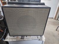
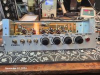
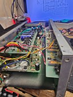
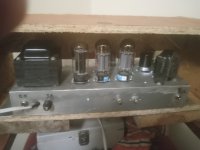
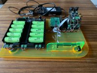
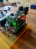
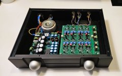
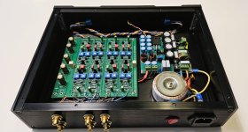
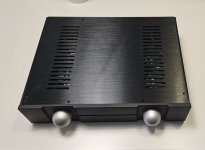
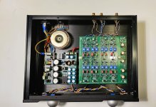
I love my Hypex DLCP-based integrated amplifier - 6 channels of UcD400 OEM with the original Hypex DLCP input board and controller. I built it almost 5 years ago, and it's been completely reliable and still sounds perfect.

One thing that I always felt, from day one, could have done with some additional features, however, was the controller.

1) Some way to control the amplifier over a wifi connection would be good when, for instance, I'm in the adjacent room and there's no line of sight for the infrared controller.

2) I would have appreciated a way to select a specific input channel directly, rather than having to scroll through the available inputs. This applies in particular to the infrared remote navigation - if I sit down in front of the TV I can barely see the characters on the DLCP display in the corner of the room, so navigating to the input selection menu then scrolling round to the 'Optical' input is a bit hit-and-miss. A dedicated key on the remote to select the optical input would be ideal.

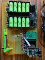
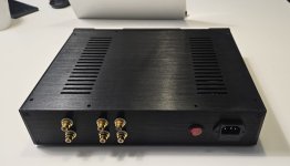
3) It would have been convenient to have a way to turn on the amplifier automatically in response to an external signal. For instance, I use a piCorePlayer as my main audio source, and this has a way to signal that Squeezelite is (soft-)powered on/off via a GPIO pin on the Raspberry Pi. It would be good to be able to use this signal to power the amplifier on/off.

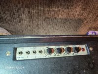
4) I find the physical button panel a little frustrating because the functions of the buttons vary depending on which part of the menu structure you're in - there are no dedicated volume buttons or channel selection buttons. To change the volume you have to use the left/right buttons to navigate to the volume setting, and then the up and down buttons will alter the volume. Similarly, to change input channel you have to use the left/right buttons to navigate to the input setting, and then the up and down buttons will change the input. Perfectly logical, but not great for everyday use. I think this was a consequence of the need to have setup options accessible via the same buttons, but for me the setup is something I did on day one and have never touched again, and I seem to recall that it can be done via a connected computer anyway.

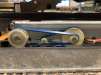
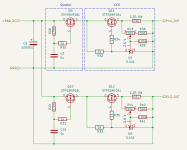
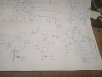
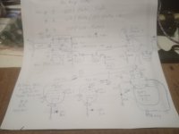
So I've had a go at building my own controller, to achieve all of these features. Hypex technical support have been enormously helpful, and furnished me with schematics for the original controller and the DLCP (for the RJ45 pinouts), as well as a description of the data protocol between the controller and the DLCP. I set about breadboarding a full controller replacement, with the following design goals:

1) All buttons to have a fixed function - e.g. up/down for volume, left/right for channel selection, centre for mute - and the display should always show both the selected input and the volume. This inevitably means that the 'setup' options in the original controller won't be implemented.
2) A wifi enabled processor, running a websocket application so that any connected clients will always see the up-to-date status of the amplifier.
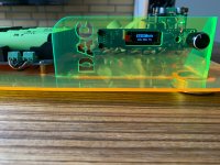
3) Form factor - since I never quite got around to having the front panel machined to accept the original controller, I could have changed the form factor completely (I'm still using a 'temporary' hardboard mock-up front panel). But I like the original form factor, so I wanted my controller to be a drop-in replacement for the original.
4) Specific inputs to be selectable via extra physical buttons, as well as being directly accessible via the infrared remote (the F1, F2, F3 and F4 buttons on the Hypex remote are perfect for this, and are otherwise unused on the DLCP). To ensure that my controller remains a drop-in replacement, the extra buttons would be added via an add-on PCB which can be mounted separately.
5) Logic pins to allow for external triggering.

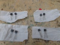
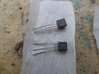
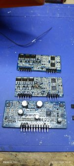
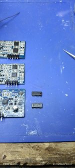
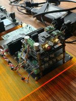
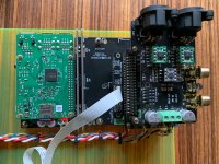
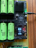
My proof-of-concept breadboard system uses an ESP32 development board, and an awful lot of jumper wires to implement all the necessary circuitry. I had a button board PCB that I'd developed previously (for a my piCorePlayer) to mirror the layout of the DLCP controller buttons, and I bought a 16x2 display to match the original. I also had a 3-button add-on board that I'd made for use with the piCorePlayer (for preset playlists etc). The controller uses MIDI to speak to the DLCP, so to get me started I bought a couple of MIDI CHIPs (from Roxxxtar Productions: https://www.roxxxtar.com/badassmidi-midi-chip), but once I was up and running I replaced the MIDI CHIP with discrete components. These parts together have allowed me to develop the ESP32 software to a point where I'm happy that all the design goals can be achieved.

Ratsnest.jpg


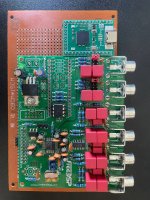
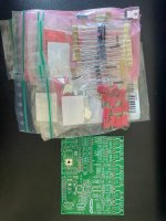
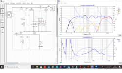
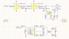
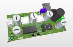
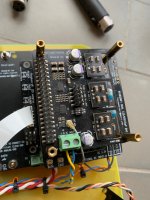
I've now designed a PCB to replace the rat's nest of jumper wires and integrate everything into something that will use the same mounting holes as the original controller. For my first version, a couple of issues prevented the PCB having exactly the same footprint as the original. Firstly, the ESP32 module is not quite as compact as the processor that Hypex used, so the PCB had to grow in height by approx 8mm, and the ESP32 antenna sits a further 8mm above that. In my amplifier's encolsure, there is room to accommodate the necessary extra 16mm of height. Secondly, the ESP32 draws a bit more current than Hypex's original processor - more than the 100mA available on the RJ45 connection from the DLCP - so this has required me to provide an additional power connection. I've used a microUSB connection for ease of use, and I plan to feed that from the 5V supply I included in my amplifier build to power my Raspberry pi 4B - it's rated at 2.3A, so there should be enough spare capacity. Other than that it should match the original: mounting holes, LCD display location, buttons and IR receiver. The first version of the PCB has been ordered from JLCPCB - It should be here in a week or so, and will require very little assembly when it arrives. I've requested them to do all the SMD soldering, so I'll only have the push buttons and IR receiver to solder in, plus the 16x2 display. Unfortunately I made a bit of a blunder with the display, and didn't make sure to keep all other components out of the way of the display PCB, so for this first version the display will be mounted in front of the PCB, rather than behind, so will protrude a little further forward than the original. Not a show-stopper for this prototype though.

V1 bottom.jpg


When version 1 arrives I'll figure out what else I did wrong and incorporate any necessary changes into version 2. I already have a work-in-progress V2.0 design under way. I've changed the through-hole push buttons to SMD, which has given me a lot more flexibility over component placement on the reverse. This has allowed me to reduce the PCB size to exactly match Hypex's original, and I've moved the ESP32 antenna within the overall footprint by clearing out a section of the PCB around the antenna. I've also added a couple of miniature push buttons to help with programming the ESP32 - not strictly necessary with a fully wired serial adapter, but there was room. I have no idea how well the ESP32 antenna will work inside the metal case of my amplifier. As noted, mine currently has a wooden front, so reception should be ok, but ultimately this will be replaced by a machined metal front. I do have the option to specify an ESP32 module that uses an external antenna, and I've even read of a hack that's possible to fit an external antenna to a module that includes a built-in antenna.

V2 Top.jpg


V2 Bottom.jpg


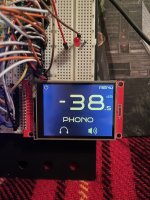
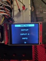
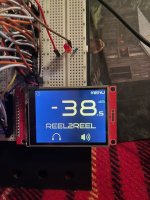
The software is 90% complete, and fully functional. The following screenshots show the software capabilities. The beauty of having my own software is that I can add extra features that weren't part of the original design goals - I've included a configuration page to rename the input channels for instance (so that the USB input becomes 'Squeezebox', and the optical input becomes 'TV'), and to configure the additional 'preset' buttons to select any of the given inputs. My PCB also includes circuitry to adjust the display brightness and contrast via PWM GPIOs, so this is configurable in the software. And I implemented an alternative volume display (a 'loudness' percentage scale, rather than dB), because the dB display is a little unintuitive for casual users. Finally there is a page to specify wifi credentials - if the ESP32 doesn't find a configured access point within 10 seconds of boot, it launches its own access point so that you can connect to it and tell it your wifi details.

Prototype.jpg


My experience of writing ESP32 software is quite limited, and I have zero experience of building an ESP32 module onto a PCB, so this will probably signal the end of the complete reliability of my amplifier! But it's been a fun and challenging project so far.

Software 1.jpg


Software 2.jpg


Software 3.jpg
  • Like
Reactions: Vavilen

Walt Jung shunt Design

Hi everyone, I intend to design some pcb for Mr. Walt Jung's shunt, I took the original schematic and added the reference GLED431. My idea is to design a pcb schematic and then make it public for those who want to print it themselves or modify it since there are none. I share the schematic I created, I would like to know if there are improvements to be made and if you need to have specific precautions in the design phase of the pcb. The PCBs that will then be created will have the rectifier part on board, and perhaps even a transformer for each branch. But let's go in order before we establish the goodness of the scheme ...

For reference : https://refsnregs.waltjung.org/.

Attachments

  • Jung schematic.png
    Jung schematic.png
    75.7 KB · Views: 2,027
  • Thank You
Reactions: YashN

High power MTM

Circling back to builds from the past....comparing how they sound today (vs what I remember Lol),
and comparing how they sound to my current DIYs in use (syn10s).

This is my first muti-way DIY project, 2015. The one that started all this !!!
PM60, designed by accomplished Australian soundman and nice guy, Peter Morris. (Thread for it on soundforums.net)

60x40 XT1464 with bms 4594HE CD; two horn loaded RCF 12"s
(pict on left, the one on right is 90 degree version with RCF 950 horn. Interchangeable horns)
Designed for use 100Hz up; mandatory sub.

1735925105820.jpeg


Here's a tuning just made in the bedroom. Too cold/windy to go outdoors, and all old tunings are hard to find/resurrect/put into newer processing platform.
So I just cranked out a new tuning without much optimization work.

Also trying to learn about VituixCAD and CEA 2034 nomenclature....so imported polar measurements for presentation.

100Hz 60 dB/oct LR high pass. Xovers at 650 and 6300Hz, also LR 60 dB/oct ...lin phase.

1735925787755.png


The box sounds great...as remembered !! Yay!! Hi-Fi PA for sure.
The power of the horn-loaded low/mids matches very well to the power of the CD. Balanced POWERUL sound.

Also pleased to say syn10 does sound better to me....a bit greater clarity throughout the spectrum .....would hate to think all the syn versions have been in vain !!!!.....hahaha

Excellent Ten Dollar Loudspeaker Tweak

Work was slow due to the holidays, and I discovered a really excellent 'tweak' for the stereo in my office.

It's called a tape measure.

I know this sounds a bit silly, but hear me out...

I got my start in audio via car audio. In the car audio world, it is virtually impossible to equalize the pathlengths of the left and right speaker. (Due to sitting off-axis.) Many people use DSP to correct the arrival times.

Everyone should try this if they have a DSP. The effect is startling; you can easily perceive the center of the soundstage moving to the left or to the right.

Nearly every stereo that I've had in my house, I have 'eyeballed' the pathlengths. Basically, I put the speakers down, and sometimes I'll do some rough measurements of where they should be located, but I rarely use a tape measure. The speakers in my house are about 10' (4.7M) away, and I'd long assumed that a pathlength difference of 3-6" wouldn't be the end of the world, because that's a difference of just 3.75%.

In my office, the speakers sit half as far away; a 4.5" pathlength difference would be a difference of 7.5%.

With some time on my hands, I got out the tape measure and measured it EXACTLY, down to the fraction of an inch.

YOWZA!!

Night and day difference. I bought me a semi decent DAC for $150 a couple of years back, and the improvement found by getting the pathlengths EXACTLY right yielded a much greater improvement than what I heard from that DAC.

Here's what I noticed:

1) Every speaker system in my house, up until now, seemed to have highs that were rolled off.

2) None of my stereo setups at the house were able to image beyond the boundaries of where the speakers are located.

3) The center image in all my systems were diffuse. There IS a center image, but it's nebulous.

Getting the pathlengths equalized solved all this.

The importance of this in a car has always been known by me, it's basically "standard operating procedure" with a car stereo, and there aren't many people who are serious about high fidelity car audio who do NOT use DSP delay. But I guess I discounted the importance of it at home, as it's more difficult to get pathlengths EXACTLY perfect in a car. In a car, I rarely move my seat and the speakers are in fixed locations, so DSP delay is a no-brainer.

I have attached two simulations to illustrate what happens when the pathlengths don't match. The sim uses a Dayton RS28A tweeter. In the first sim, there are two RS28As, three meters from the listener. Each side of the triangle is 3.46M long.

The sims illustrate that the stereo response is flat at the listeners seat but only when they're 100% equidistant. When a single speaker is moved just 4.5" (114.3mm) on the Z axis (distance), comb filtering rears it's ugly head.

And I think that is why the treble sounds so much cleaner and clearer when the spacing is exactly right; even a difference of a fraction of an inch makes a difference.

Even more exciting, is that the sound staging and envelopment is just night and day too. For instance, I was listening to something tonight, using this setup, and noticed that the center of the stage had drifted to the left by about 15-30cm. At first I thought that maybe something had gone wrong with my equipment, but then the soundstage 'snapped' back into the center, and I realized that the issue was the recording itself.

IE - the pathlengths were so tightly aligned, I was able to perceive something that I hadn't noticed before in the recording.

Attachments

  • Screenshot 2025-01-03 005322.png
    Screenshot 2025-01-03 005322.png
    167.1 KB · Views: 86
  • Screenshot 2025-01-03 005303.png
    Screenshot 2025-01-03 005303.png
    127.2 KB · Views: 94
  • Screenshot 2025-01-03 005254.png
    Screenshot 2025-01-03 005254.png
    30.8 KB · Views: 93

sealed equation

hi ages ago someone gave me an equation for working out the 3db point of a woofer in a sealed enclosure . it was something like 0.707 ÷ qtc x fs
and then there was another one for working out the ideal size of the enclosure I can't remember either of them .
does anyone know these equations and could share them with me . I havnt used them for a while and I cant quite remember them now .
thanks in advance

Finding genuine UPC1237?

I have some builds in progress that require UPC1237 speaker protection ICs, but how do I find genuine ones (ideally in EU)?

I have a couple of older amplifier boards that don't work and I am pretty sure the ICs I put in (from ebay/aliexpress) are the culprit. Since they are also a PITA to remove once soldered in place I would like to ensure I get genuine ICs, but I am not sure where to go as the "usual suspects" don't seem to carry these?

VSP Labs Trans Mos 150 - Bias?

I bought this amp used about 1984 and it's served me well all these years. Still works perfect but I thought I'd treat it to some bench TLC.
After blowing out the dust it went to the test bench where i warmed it up for 20 minutes boosting a 1kHz input to 50watts output.
I tweaked the offset to under 1mV.
Then I checked the bias of each channel by removing the B+ fuse and contacting a digital ammeter in its place. They were in the 300-350mA range at idle (zero signal), into 8ohm loads.

I don't know what the bias should be, and this amp has the reputation of running pretty warm--possibly due to a rather highish bias setting.

Anyone KNOW? SWAG not needed--I can guess without any help. 😉

17358642665396529113232554890579.jpg

Fixing High-Frequency Ringing on the Marantz 2225: A Simple Yet Incredible Discovery

Hi everyone,

I recently made an interesting discovery while working on a Marantz 2225 amplifier. While the amp is generally great and has a tone I really enjoy, I always felt something was a bit off in the mid-high and high-frequency range. The upper frequencies seemed to lack coherence, almost as if they were blending together in a way that didn’t sound quite right.

Curious if this was unique to my unit, I reached out to two other people who own the same amplifier to compare notes. It turns out their amps exhibited the same issue. So, I decided to investigate further.

While troubleshooting, I noticed something on the oscilloscope that I had previously overlooked—a high-frequency ringing in the signal. At first, I didn’t think much of it, but it kept nagging at me, so I decided to address it.

The solution, as it turns out, was incredibly simple, but the impact on the sound was nothing short of amazing!

The Fix
The fix involves adding a pair of 152J (1.5nF) capacitors across the feedback resistors (see the attached picture for the exact placement). This small tweak completely eliminated the high-frequency ringing and brought a new level of clarity and coherence to the mid-high and high-frequency range.

After applying the fix to my own unit and experiencing the improvement, I reached out to the two other owners of the Marantz 2225 and offered to perform the same modification on their amps. They both called me after trying it out and said they’d never heard their amplifiers sound this good before!

The transformation is absolutely incredible—it’s as if the amp has been unlocked to its full potential. The highs are now crisp, the mid-highs are beautifully clear, and the overall sound has a newfound precision and warmth.

If you’ve been noticing similar issues with your Marantz 2225, I highly recommend trying this simple mod. The improvement is well worth it, and it’s a straightforward fix for anyone comfortable with a soldering iron.

Feel free to share your thoughts or ask any questions! I’m curious to hear if anyone else has experienced similar issues or tried other modifications to enhance the sound of this classic amplifier.

Attachments

  • modific 1.JPG
    modific 1.JPG
    280.5 KB · Views: 111
  • sqare 1.JPG
    sqare 1.JPG
    84.2 KB · Views: 92
  • sqare 2.JPG
    sqare 2.JPG
    86.5 KB · Views: 72
  • cap.jpg
    cap.jpg
    159 KB · Views: 87
  • schem 1.JPG
    schem 1.JPG
    184.6 KB · Views: 93
  • Like
Reactions: indianajo

Sony CDX-R88 DC/DC converter

Dear all, I'm tryng to repair my Vintage Sony CDX-R88. I found the DC DC converter fault due to electrolitic lake.
I ask to everithing of someone can help me to find and old stock DC DC converter or the Electric diagram of It (It Is a nichicon).
In the picture below, you Ca ready the party Number

Sony 1-464-953-11
Nichicon ZSSR654D
I'm also looking for a cdx-r88 fault to buy for spare parts
I'm locate in Italy
1000031229.jpg

6AS7G SE output stage operating point?

So I have been looking at a bunch of different 6AS7G output stages (single ended NOT OTL). I have come across some different operating points. One I found at 280v, 90v cathode bias 90mA per section... which is a little over max plate wattage. Another is 245v, 77v cathode and 77mA per section.

I am looking to do 1 6AS7 per channel, so paralleled sections. 8-10W output.

Any guidance as far as a good operating point for them? Of course I will get matched 6AS7... in fact I have a box of 6080's that I was going to use for another project but never did.

Input stage... no idea. NFB... no idea.

Richard

DAC R2R Construction

Good evening, I am trying to build an R2R DAC I purchased from AudioPhonics, and this is the one. My problem is that in the single-ended configuration, I have a positive output from the channels, but following the schematic, I need to connect it to the negative input of the operational amplifier, which results in a negative voltage on the RCA outputs. Can someone help me understand where I might be going wrong? Thank you very much!

https://www.audiophonics.fr/en/dac-...2023-r2r-dac-module-24bit-384khz-p-17986.html

Hello there!

Hello!

I've just joined this forum, mostly to learn and get support for my project. I'd like to build a 2.2 (or possible 3.2) with a PC source. While I have knowledge on the software side, for DSP and electronic aspects, I will have to learn a lot! I'm planning to start with Linux/CamillaDSP and "DIY" (mostly integrating modules, possibly small adaptations, but just starting!) multi channels DAC. For amplifier and speakers I will rely on the market for now!

Troubles with an EIZZ double gang 24 step volume pot

Guys, I need your kind help: I'm trying to assemble my first ampli using the 3e AUDIO 260-2-29A modified to accept SE input signal. I'm an absolute beginner in this matter and I tried to get as much infos as I could out of other knowledge. I tested the board with a cheap LDAC using my phone as a source and it sounded great. Then, since I took the chance to grab a 100k logarithmic pot by EIZZ at a very good price, I connected it between the LDAC and the ampli input. Well with great surprise and disappointment was terribly bad with the sound level constantly low all along the swipe and getting to max at the last two steps of the pot! The pot pins are marked as "IN-OUT-GND". I connected the LDAC output to "IN" and the ampli input to "OUT".
I replaced the EIZZ with a cheap linear pot getting a decently gradual regulation of the volume.
See in attachments a chart comparing the EIZZ and the linear pot resistance curve: they appeared quite nice, don't they?
Can't believe I'll have to get rid of the EIZZ for a cheap linear pot!
I have no clue on how to work this around!
What am I doing wrong?

Attachments

  • Capture.JPG
    Capture.JPG
    72.2 KB · Views: 89
  • Untitled.png
    Untitled.png
    7.1 KB · Views: 93

Weather station battery blues

I have a couple of Ambient Weather local stations, they measure weather at my house and display it as well as uploading it to the Interwebs.
One has been in service for a couple of years, the other was given to me by a friend who was having trouble with it. Mine is the WS-2000, the one from my friend is the WS-2902. They use the same outside array, but the inside panels are different. The senor array looks like this:
WH-65B weather station.JPG


The one that came from my friend I hope to put at the local library so that we have a weather station right in the middle of our little village.

The problem is that they both go thru batteries a lot faster than they should. They claim to be solar powered, using 2xAA batteries as backup. The batteries are supposed to last a long time, but they don't. Mine eats a set of AA every 3.5 months, the other one a set every month. 😡 It's no fun getting to these sensors way up a pole to change batteries. No way can I have the unit at the library needing new batteries every month, it simply would not get done.
As you can see, there is a small solar cell at the top and it is supposed to power the unit in the daytime, and inside there is a 2F super cap that should power it at night. That is sort of working, at least with mine. With the station that could go to the library, either the super cap or the solar cell - or both - seem to be bad.

How much current does this draw? I just measured the "bad" sensor seen here. After start-up it draws 2.0-2.3 mA (it fluctuates a bit.) Every few seconds it draws a very brief burst of 3.5mA when it transmits. So I'm going to call it 2.5 mA average draw. Not too bad for a battery powered device. But here is my thought: What if I went to 2xD cells instead of AA? I would wire into the senor battery compartment and run a wire down the mast to a weather proof box that holds the D cells. That would certainly make the batteries easier to change out. D cells have a much higher mAH rating than AA cells so maybe that makes sense.

But how long would the sensor run on two alkaline D cells? Count that mine runs about 3.5 months on 2xAA while the bad one runs about 1 month on a set. What do you think?

Crossover

Hello all.

I was hoping to get your professional help in understanding the impedence and phase readings of my
very first crossover made in Xsim.

Any significant faults in the crossover design?
How does impedence and phase look?

Thank you very kindly in advance

Attachments

  • CROSSOVER.jpg
    CROSSOVER.jpg
    31.3 KB · Views: 64
  • FREQUENCY RESPONSE.jpg
    FREQUENCY RESPONSE.jpg
    102.9 KB · Views: 69
  • IMPEDANCE.jpg
    IMPEDANCE.jpg
    96.2 KB · Views: 69

Built A 6L6 GC Tube Guitar Amplifier

Check it out ! , 6L6 GC , 12AT7 PI and 12AX7 pre amp. 5U4 GB Rectifier. 484/483 on the plates, 416 screens and 44.5 negative bias, fixed bias. 150/147 on The 12AT7 plates and around 215/210 on The 12AX7 plates. I'm only using 3 half stages right now for the pre Amp. And I just have Volume Treble and Bass so far. But with the 1 Meg pots I get a lot of Adjustment. You can dial it in pretty good to the sound you want. I wanted to have A Rectifier tube and Vintage Iron's in it and They are 1960 Iron's from A Whirlitzer Organ. I built my own chassis and case for it. Cost me 60 bucks for a tig welder and I had to do some work cutting up work with the aluminum for the chassis but it is My own design and spec's. I laid everything out the way I wanted it to be. I will put a drawing with the pictures of it. I'm not completely done with it yet but I will finish it. Right now I am just playing it some and getting used to it. I have to be sure it is going to be dependable. It wasn't that cheap to build , but they are very expensive to buy new if they are hardwired with A tube rectifier. I grew up with hardwired tube amps in The 1960's. There's just something special about them. This is the third one I built with Old Iron's and I'm hoping it lasts longer than the other two did, they both Lost Their output transformers and I couldn't get the right one's Used for either one of them. One was a EL 34 Ultra Linear and I really liked that one. You can't find those kind of output transformers anymore. I think I kept it for almost 20 years looking for that transformer before I finally gave up on it. To me the amplifier is just as important as the guitar to playing , it's got to feel and sound right to me through the strings. Anyway check it out and let me know what you think. I just changed the negative bias E Caps tonight because I didn't have the right ones when I first built it. They were working okay but 65 years is a long time for E Caps. My conscience was telling me to change Them before I lost the negative bias and smoked the tubes. This is the first Guitar Amp I've had that actually sounds good with JJ output tubes. They sounded terrible in my Fender 60 Watt DeVille. I think that they couldn't handle The higher screen voltage Very well on The Fender , that's about the only real difference between the output of two amplifiers. I put a few drawings in for those interested. Have a great day !

Attachments

  • IMG_20250103_035547.jpg
    IMG_20250103_035547.jpg
    224.2 KB · Views: 55
  • IMG_20250103_035628.jpg
    IMG_20250103_035628.jpg
    243.3 KB · Views: 53
  • IMG_20250103_035520.jpg
    IMG_20250103_035520.jpg
    157.1 KB · Views: 50
  • IMG_20250103_035515.jpg
    IMG_20250103_035515.jpg
    224.8 KB · Views: 52
  • IMG_20250103_035506.jpg
    IMG_20250103_035506.jpg
    203.2 KB · Views: 56
  • IMG_20250103_035444.jpg
    IMG_20250103_035444.jpg
    191.2 KB · Views: 52
  • IMG_20250103_035439.jpg
    IMG_20250103_035439.jpg
    156.4 KB · Views: 48

New member

444 / 5,000

Translation results​

Translation result​

I was looking for information about audio and its design and I found this page.I studied mechanics and electronics, and I made my first amplifier when I was 15 years old. 1985-1987I have been working for 25 years in hardware design, and I have gathered a lot of experience, but after all that, I know that I have learned very little in the vast field of knowledge. I think it is an ideal place to be in contact with people with similar interests and share experiences.
Thank You!

EMI / EMC / RFI issue: Class D amp causing hum in subwoofer amplifier

Since upgrade of my Class D power amp with NewClassD Singularity 3 modules (formerly Singularity2, wiring and case exactly like before), I have significant 50Hz-ish hum in my subwoofer. It only kicks in when the power amp is on and speakers engaged, turning down the volume on the sub does not stop it. I had NO problems using the exact same setup prior to the upgrade nor with several other Class D amplifiers.
The hum is arising in the subwoofer only, and goes away if subwoofer is turned off (obviously) or power amp is turned off. Other electronics nearby (including player/DAC, class A/B amplifier, miniDSP, phono amp, headphone amp) do not seem disturbed. There is absolutely no hum coming from the class D amp, so I figure the sub is picking up RFI which is overwhelming it's noise filter and letting in hum from mains or elsewhere (the high switching speed of Singularity3 may be why it doesn't happen with the other amps).

I have tried a number of things including adding clip-on ferrites to cables and so on. Initially I found that proximity of the subwoofer power cable to the speaker cables (unavoidable in my setup) was causing hum, so I installed a shielded and grounded power cable on the sub, and with addition of a ferrite internally and further two just outside the plate amp, the power cable no longer seems at issue. BUT I still get hum if I connect a signal cable. It doesn't make a difference if it's straight from the DAC/Player LFE output, or from the miniDSP. I have a voltmeter that can measure frequency (no oscilloscope unfortunately), however I can't seem to measure any electrical signal causing the hum (e.g. not between signal cables and disconnected sub). I don't hear hum when connecting the headphone amp directly to the sub end of the cables. A different an much cheaper subwoofer is also unaffected.

The Class D build is pretty much by the book in a grounded aluminum cabinet, dual mono wired up exactly as described in the v.300 instructions https://lctechs.dk/newclassd/index.php?page=15&hv=1 on page 28, but with the addition of an extra wire connecting input ground to one end of the ground cable at the power supply end of the modules - this connection was present in the Singularity2 build and wasn't causing problems so I decided to keep it.
I did install ferrites on the power supply cables to the modules, but due to cable length and thickness I couldn't run them through twice as shown on page 19 of the instructions, also I have ferrites on the speaker cables as shown on page 25, although I don't have the RFI caps installed (but neither did the Singularity2 build, or for that matter an older build which is not causing hum).

Sorry for the long writeup, but I am at a loss on what to try next? RFI caps? Ground loop breaker? further changes to subwoofer amp power supply?
Ideally I guess would be to stop the RFI at the source - but it'd also be great if I could stop it from entering the subwoofer amplifier...

Any experiences and ideas much appreciated!!!!

Seeking Kenwood AT-52B Audio Timer Owner and Service Manual

Hello everyone,

I hope this message finds you well. I'm currently in the process of refurbishing a Kenwood AT-52B Audio Timer and am in need of the owner and service manuals to ensure I do everything correctly. If anyone has a copy of these manuals or knows where I can find them, I would greatly appreciate your assistance.

Thank you in advance for your help!

Best regards,
MA

  • Locked
For Sale Ian Canada DAC/Streamer for sale

Hi All

I am selling my fully built DAC using IanCanada parts. It plays amazing.
Assuming that anyone here already have some knowledge of the different boards by Ian Canada, here is the list of the included boards:
  • LifeO4 mkII battery PSU, incl. 10 x A123 batteries + holders (LifePO4)
  • StationPi PCB
  • FiFoPi reclocker ultimate + upgraded NDZ clocks (45.1584 + 49.1520 MHz)
  • ReclockPi - additional reclocker for even lower Jitter
  • ES9038q2m dual mono DAC
  • I/V STD - analog stage with upgraded Opamps: 1x Opa 1622 - 2x Opa 1612a.
  • ESS controller - small burn-in at screen but new one is supplied (must be soldered on)
  • Extension kit for ESS controller
  • Laptop PSU
  • Raspberry Pi 2 with Volumio OS preinstalled
Everthing is mounted on a self designed laser cut DIY acrylic test plate. This can of course be removed if you don't like it.
The DAC and LifeO4 have previously been used in a 3 power rail configuration but have been reverted back to single rail (see last photo). Fully tested and still plays amazing in the given configuration with the I/V STD.

Selling price is 485€.

All boards that are included into this DAC are listed above. Please contact me if you have any questions or something is not making any sense.
I am not selling individual parts.
I will happily ship within the EU and Please contact me for shipping quotes.

It will probably be too expensive to ship the parts abroad, but don’t hesitate to contact me… Expect at least +50€ or more.

I will accept PayPal. Please add 5% to the entire order including shipping if a regular PayPal transaction is preferred. “Friend to friend” transfer (no fees) is also acceptable but entirely up to you.

Regards Mikkel

Attachments

  • IMG_4545.JPG
    IMG_4545.JPG
    913.8 KB · Views: 160
  • IMG_4547.jpg
    IMG_4547.jpg
    1,006.5 KB · Views: 157
  • IMG_4548.JPG
    IMG_4548.JPG
    1 MB · Views: 145
  • IMG_4551.JPG
    IMG_4551.JPG
    837.8 KB · Views: 134
  • IMG_4553.JPG
    IMG_4553.JPG
    706.7 KB · Views: 135
  • IMG_4554.JPG
    IMG_4554.JPG
    849.1 KB · Views: 136
  • IMG_4555.JPG
    IMG_4555.JPG
    753.9 KB · Views: 135
  • IMG_4556.JPG
    IMG_4556.JPG
    895.4 KB · Views: 134
  • IMG_4544.JPG
    IMG_4544.JPG
    739.4 KB · Views: 141
  • Like
Reactions: Pepousek

Ian Canada DAC/Streamer + LL1544a for sale - Fully built

Attachments

  • IMG_4545.JPG
    IMG_4545.JPG
    913.8 KB · Views: 208
  • IMG_4544.JPG
    IMG_4544.JPG
    739.4 KB · Views: 195
  • IMG_4547.jpg
    IMG_4547.jpg
    1,006.5 KB · Views: 189
  • IMG_4548.JPG
    IMG_4548.JPG
    1 MB · Views: 181
  • IMG_4551.JPG
    IMG_4551.JPG
    837.8 KB · Views: 177
  • IMG_4553.JPG
    IMG_4553.JPG
    706.7 KB · Views: 169
  • IMG_4554.JPG
    IMG_4554.JPG
    849.1 KB · Views: 170
  • IMG_4555.JPG
    IMG_4555.JPG
    753.9 KB · Views: 171
  • IMG_4556.JPG
    IMG_4556.JPG
    895.4 KB · Views: 189

Biamp 6-24 Crossover

Pass Labs biamp 6-24 Crossover assembled as per discussion thread and related BOM (230Vac) fully functional, for sale at 350€.
From Italy to EU per €350 + shipping.

I assumed people here already know this product, clearly discussed and explained in the discussion thread in the Pass Labs section:


Frequency and slopes are adjustable,
  • slope (from 6dB up to 24 dB) by dip switches,
  • frequency by capacitors inserted into their pin header female.
There are also four rotary potentiometers each way, to change frequency by a factor about 10.
Thank you,
Max

Attachments

  • Biamp 6-24 Crossover 1.jpg
    Biamp 6-24 Crossover 1.jpg
    236.8 KB · Views: 127
  • Biamp 6-24 Crossover 2.jpg
    Biamp 6-24 Crossover 2.jpg
    295.8 KB · Views: 114
  • Biamp 6-24 Crossover 3.jpg
    Biamp 6-24 Crossover 3.jpg
    163.9 KB · Views: 107
  • Biamp 6-24 Crossover 4.jpg
    Biamp 6-24 Crossover 4.jpg
    154.8 KB · Views: 107
  • Biamp 6-24 Crossover 5.jpg
    Biamp 6-24 Crossover 5.jpg
    258.3 KB · Views: 108
  • Biamp 6-24 Crossover 6.jpg
    Biamp 6-24 Crossover 6.jpg
    182.8 KB · Views: 108
  • Like
Reactions: mordikai and JRKO
Projects by fanatics, for fanatics
Get answers and advice for everyone wanting to learn the art of audio.
Join the Community
507,765
Members
7,887,461
Messages

Filter

Forum Statistics

Threads
406,177
Messages
7,887,461
Members
507,765
Latest member
aleminx