HP339a Modification Summary
Introduction
The HP339a was a state of the art distortion analyzer in the 1980s.
It was and is a full featured all-in-one product including a volt meter,
low distortion oscillator, analyzer, AM detector, and VU meter.
There was an in-depth analysis of low distortion oscillators
on DIYAudio on the following link:
<Low-disortion Audio-range Oscillator>
This was followed by a specific HP339a thread, linked here:
<HP339a>
This is a summary of those threads along with the links, conversations, and
posts, about the research and development that went into the suggested modifications to the venerable HP 339A.
Outline
Why HP 339A?
Cheapest quality instrument for DIY mods
From Post #1146:
The 339A is about the cheapest instrument that DIY'ers will ever be able to do simple mods to (parts, value changes and IC replacements) and get excellent results. However, next up the ladder of affordability might be the popular HP 8903_ or others? If the full potential can be realized in that one or other readily available used gear, what rewards will they bring? This little 339A exercise shows us there is a lot that can be had in refurbishing them for improved performance and that the fundamental design is sound.
-- just change the IC's and a few caps and trimmers and you are done with the mods. Then just use its' own analyzer to tune the thd with the trimmers for a null. That's about it. The nice thing about the 339A is that it has a wide range of frequencies and it can be used as an rms voltmeter with db scales. The analyzer will accept a wide range of voltages on its input. It will give you a fast indication of the thd+n with a minimum of fuss and cost less than any other options.
We here got carried away with the oscillator and have been curious as to how low can we make it can go... far lower than the THD meter/analyzer part... but an indication well under .001 (-100dB) should show that you have a pretty good amp/preamp circuit.
The 339A is about the cheapest instrument that DIY'ers will ever be able to do simple mods to (parts, value changes and IC replacements) and get excellent results. However, next up the ladder of affordability might be the popular HP 8903_ or others? If the full potential can be realized in that one or other readily available used gear, what rewards will they bring? This little 339A exercise shows us there is a lot that can be had in refurbishing them for improved performance and that the fundamental design is sound.
Wide range of frequencies and input voltages
From Post #1577:-- just change the IC's and a few caps and trimmers and you are done with the mods. Then just use its' own analyzer to tune the thd with the trimmers for a null. That's about it. The nice thing about the 339A is that it has a wide range of frequencies and it can be used as an rms voltmeter with db scales. The analyzer will accept a wide range of voltages on its input. It will give you a fast indication of the thd+n with a minimum of fuss and cost less than any other options.
We here got carried away with the oscillator and have been curious as to how low can we make it can go... far lower than the THD meter/analyzer part... but an indication well under .001 (-100dB) should show that you have a pretty good amp/preamp circuit.
Accepts up to 300 Vrms on attenuated input
Similar to Dick Moore's project
From Post #1554:
For all those thinking of using an HP339A and want to improve it:
I just looked at a similar project by Dick Moore. He copied the 339A oscillator circuit and put it into another existing chassis. Didn't use the 339A analyzer section. If you go to his site, you will get a well written, detailed summary of what to do on the oscillator. -- RNMarsh
Link to Dick Moore's Lab Pages
Our colleague, Dick Moore (aka RichEEM), and his mod pages w/FFT plots:
http://www.moorepage.net/IG-18-3.html
http://www.moorepage.net/IG-18-3.html
Base line performance.
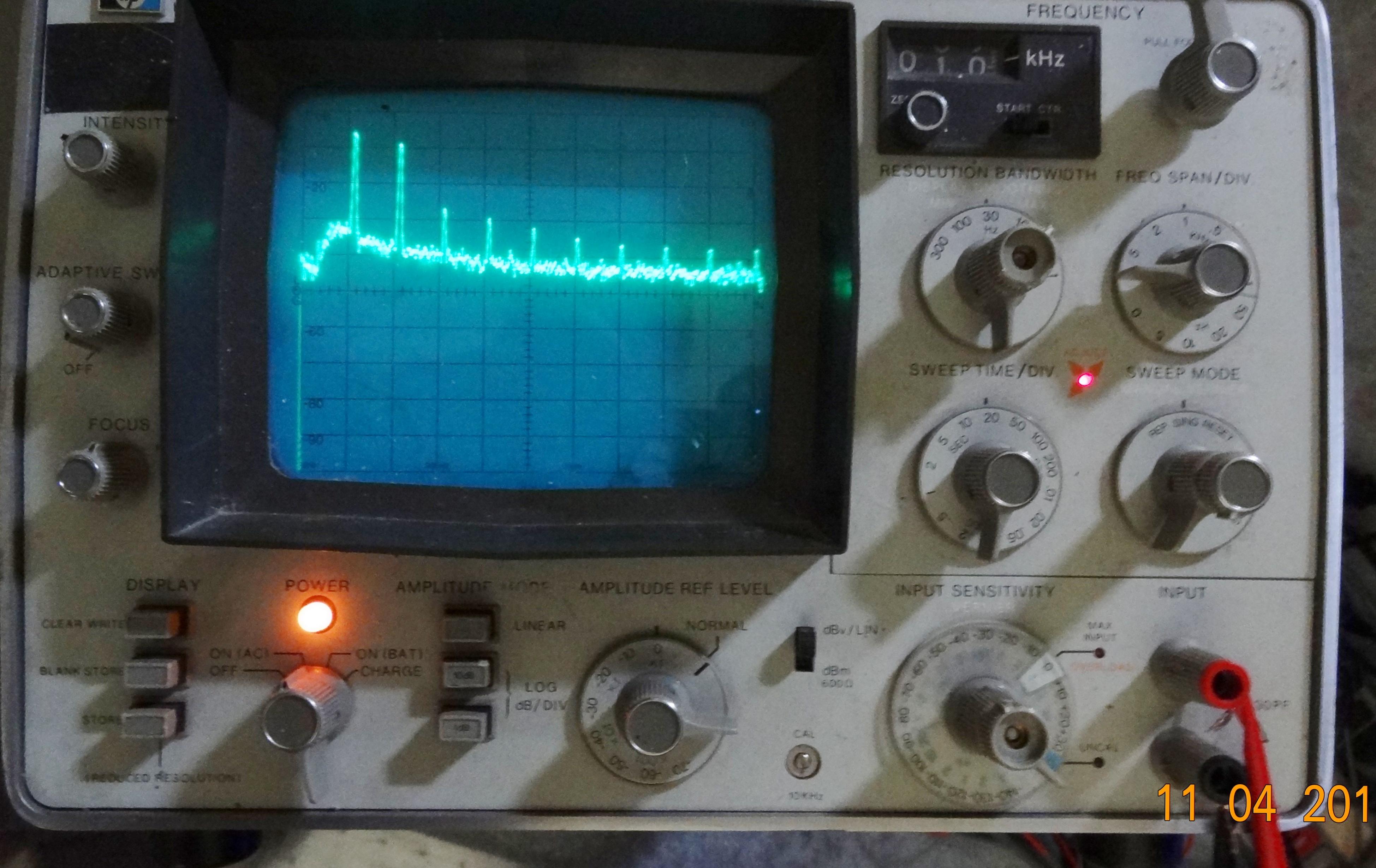
From Post #980: Low Distortion Analyzer
Being able to have a wide range of test freq is a nice convenience.
So far the complete HP339A system -- reading its own oscillator at almost stock (oscillator + analyzer distortion) - with just a tune up and changing the two null trimmers (using a 3580A spectrum analyzer on the output monitor port of the 339A) -- gives a noise floor of -145. Harmonics, H2 is -105 and H3 -130. Its a good beginning and its getting better! :-) Thx-RNMarsh
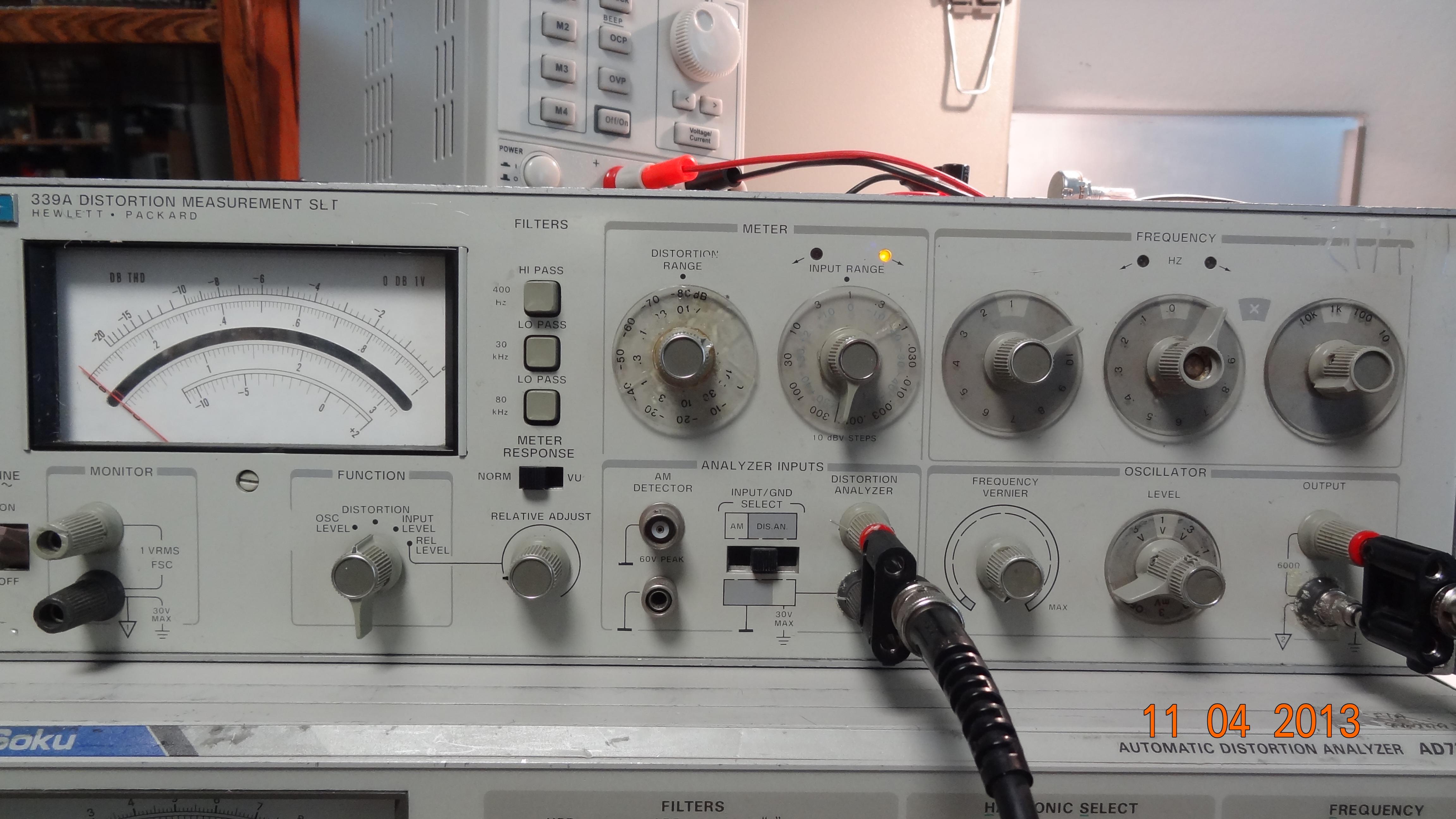
Intro to the 339A boards. Unmodded
1. Pic
2. Pic
3. Pic
4. Pic
5. Pic
Stock 339A Performance Numbers -
Being able to have a wide range of test freq is a nice convenience.
So far the complete HP339A system -- reading its own oscillator at almost stock (oscillator + analyzer distortion) - with just a tune up and changing the two null trimmers (using a 3580A spectrum analyzer on the output monitor port of the 339A) -- gives a noise floor of -145. Harmonics, H2 is -105 and H3 -130. Its a good beginning and its getting better! :-) Thx-RNMarsh
Intro to the 339A boards. Unmodded
1. Pic
2. Pic
3. Pic
4. Pic
5. Pic
Modified HP339A Performance Numbers
FFT Plots w/Test Equip
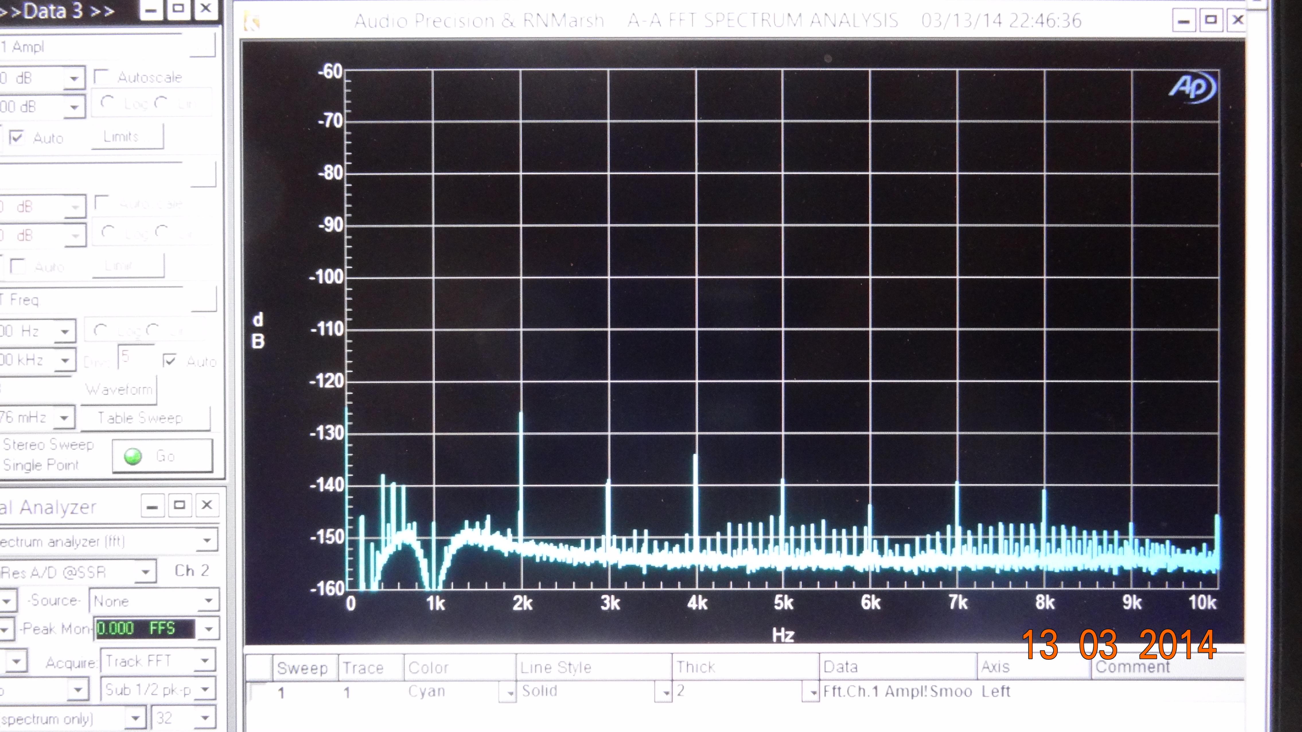
From Post #2156:
The 339A is a thd+N meter. The osc and analyzer spec is .0018% or better. That is a tick below the 0.2 mark on the 0-1 scale (-80dB =1).
After opamp and parts changes and upgrades, the thd+n is near the 0 mark -- well below -100dB. This is THD+N.
Using the 339A monitor output shows the two dominant harmonics, 2H at -106 dB and 3H at -110 dB. The top is -100 dB and 10 dB/div. and measured with shibasoku 725D analyzer ported to an HP 3580A Spectrum Analyzer to measure individual harmonic and noise levels. This is a compromise tuning for a wide range of freqs; For minimum thd+n at only one freq, it can be much lower:
Things to be careful about
Careful when making adjustments that you don't short the case of the Jfet.
It's very close to one of the trim pots and if it shorts it's toast.
Stability Build Before Modding:
1. Testing and Replacing power supply electrolytic capacitors.
2. Other Platform stability building.
It's very close to one of the trim pots and if it shorts it's toast.
Stability Build Before Modding:
1. Testing and Replacing power supply electrolytic capacitors.
2. Other Platform stability building.
Modifications
Most bang for the buck.
Davada - Explains the HP339a configuration
and the limitations of the mods:
Davada - Explains the HP339a configuration
and the limitations of the mods:
Output Level Pot
Davada - Post #48:
Davada found the output level pot to be a source of distortion. You can
find the voltage level output pot for under $10 at Mouser or other suppliers.
The pot is a Bourns cermet type, p/n 51SADU25A15L.
The output level pot is easy to change. Loosen the screws on the shaft extender and spin the nuts off. 20 min tops. The pot shaft is longer than needed so you
have to cut it to proper length about 8 to10 mm.
Oscillator and Pot change
From Post #45, #47 (HP339a):
If you wanted to do the minimum, just changing the oscillator opamp
(AD797 etc) and replace its control pot with a new multi-turn and add
another trim for the fixed resistor that is feedback on the control jFET (d-g)
with a multi-turn (for 2H only).
But, a must do is replace the output level pot. That pot introduces a lot of harmonic distortion. -- 31697B (RNMarsh)
Most used oscillator change
From Post #75 HP339a:
The bottom of the board is completely exposed once the analyzer is opened up.
It's a bit tight from the top of the board but all your doing is inserting
components. Just remember to remove all the compensation and clamping
components around the op amp for the oscillator.
If you use an LT1468 the compensation is wrong and not needed.
There's is not much to go wrong. Just be careful when making adjustments
that you don't short the case of the Jfet. It's very close to one of the pots and if it shorts it's toast. --Davada
FFT with These Mods
A1 Board Oscillator Schematic
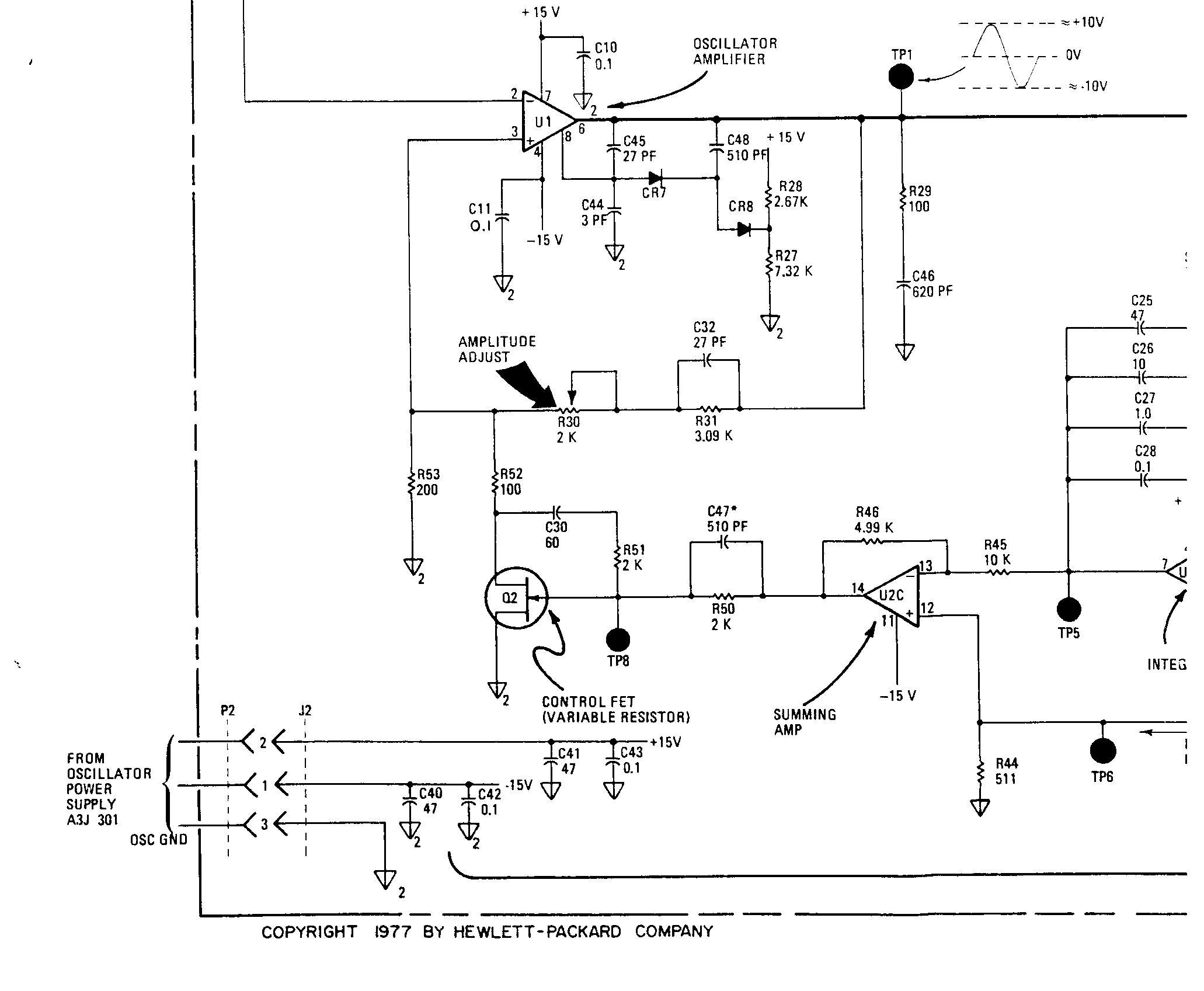
A1 Board Specific Mods
From Post #86:
The jFET feedback R51/2K.
Replace with 28 turn pot/trimmer. It is in series with a 60mfd cap (C30)..... together they go from jFET gate to its' drain. Replace C30 with 100mfd 105c bipolar.
The Oscillator Amplitude Adjust pot (R30/2K)
Replace, as it's
old, has contact issues, and makes the adjustment difficult and 'touchy'.
old, has contact issues, and makes the adjustment difficult and 'touchy'.
The output pot is R3 (10K). Replace.
Replace:
Bourns cermet, p/n 51SADU25A15L
Bourns cermet, p/n 51SADU25A15L
HP ID: A1U1
Replace Oscillator with Linear Technology OpAmp LT1468. These simple mods are all you need to do to have the level of THD shown.
Notes and errata
Service/Test Notes
PhotoCell LED Measurement
Dick Moore wrote this up to help us
test the Photocells and see if they are
still good or not. Thank you Dick, R.I.P.
It's located in this thread by stevecooke (Look he even got his own flag too.)
 HP339A distortion analyser linked here: LINK
There is good stuff here and specifically about the
LED Test that dick moore suggests at post #39: LINK
No link, I'll just post it here:
@tschrama -- lack of auto tuning in the notch filter, most likely caused by a bad amp or other component. This circuit looks complicated just due to the large number of components, but it is fairly simple. Two opto-resistors (LED and photocell in a sealed package) do the actual tuning adjustments -- they are known to be problematic. Just use a diode tester to check the LED section.
If that's good, then try measuring the resistance of the photocell -- it should be very high if the LED is off. If it's low that's a problem. Conversely, if the LED is OK, then put 1kohm in series with it and run it slowly up on a variable DC supply (make sure polarity is correct) and measure the photocell R -- it should go down as the LED intensity increases. But note other comments above, about the need to check the input circuits to be sure signal is actually getting to the notch filter and the tuning circuitry.
Good luck.
__________________
...................
Dick Moore
Link to Post#39
Basic Mumbo Jumbo
Hocus Pokus Dominatrix
Read up to about post #2300 in the low distortion analyzer thread.
Start: Photos before mods example
End: Photo after mods exemplary example
How to, that is what to do.
test the Photocells and see if they are
still good or not. Thank you Dick, R.I.P.
It's located in this thread by stevecooke
(Look he even got his own flag too.)There is good stuff here and specifically about the
LED Test that dick moore suggests at post #39: LINK
No link, I'll just post it here:
@tschrama -- lack of auto tuning in the notch filter, most likely caused by a bad amp or other component. This circuit looks complicated just due to the large number of components, but it is fairly simple. Two opto-resistors (LED and photocell in a sealed package) do the actual tuning adjustments -- they are known to be problematic. Just use a diode tester to check the LED section.
If that's good, then try measuring the resistance of the photocell -- it should be very high if the LED is off. If it's low that's a problem. Conversely, if the LED is OK, then put 1kohm in series with it and run it slowly up on a variable DC supply (make sure polarity is correct) and measure the photocell R -- it should go down as the LED intensity increases. But note other comments above, about the need to check the input circuits to be sure signal is actually getting to the notch filter and the tuning circuitry.
Good luck.
__________________
...................
Dick Moore
Link to Post#39
Basic Mumbo Jumbo
Hocus Pokus Dominatrix
Read up to about post #2300 in the low distortion analyzer thread.
Start: Photos before mods example
End: Photo after mods exemplary example
How to, that is what to do.
Parts
from post #1102:
For the two null adjust trimmers, the center wiper goes directly to 15vdc; I used Spectrol cermet multi-turn trimmers (500 Ohm); 3/8th inch square. Now sold thru NTE Electronics Inc. Avail at Mouser. USD 1.50. They have multi-finger precious metal wiper for long term set point reliability and excellent wiper contact. - 31697B
from post #1104:
$27.25 will get you a Vishay Accutrim 1K bulk foil trimmer at Digikey.
Resources
Work arounds
To do
To not do
Don't Sweat it
Post #7:
When I turn it on, no matter what the input scale is, the meter swing to the very far end, then I turn it off immediately because I don't want to damage it. I wonder I should let its power on and let it have a chance to settle down.
Does your HP339A behave like this on powering up?
Post #8:
HP pulled a boner on the meter drive circuit.
Post #12:
Mine did that too. It sat on the shelf for over a year after i first got it as i thought it was broken!
Finally Post #14:
Explained by Davada,RIP as the following:
This is normal for 339A.
Looking at the meter amp I see why.
Until the Q1 Jfet is biased off the meter is at full deflection.
David.
https://www.diyaudio.com/forums/atta...-meter-amp-png
or
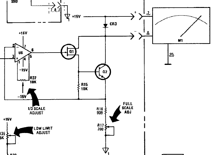
Post #15: Why no meter damage?
That tracks.... Making Diode CR3 an anti-smoke clamp limiting voltage to one junction drop max across the movement. But being old Hp, these are jeweled Darsonval meter movements, not taught band types, so they'll take pegging more gracefully.
And finally Dick Moore RIP, Post #16:
The mechanical design of the 339 and similar era gear was not HP's finest moment. The knobs are terrible -- weak, prone to break or crack, the dial skirts pop off the knob, and the printing is hopelessly fragile. I've used a very fine-point Sharpie to ink in the markings but it's a lousy fix.
On the good side, the 339 is a pretty good analyzer if you can live with about 0.001% as best resolution. The null floor is decent at about -110 to -115dB, so higher resolution is possible. The quad op-amp in the filter circuits needs to be replaced with a quieter unit, especially if you use the analyzer output to drive a wave or spectrum analyzer.
The oscillator is quite good -- better than the analyzer, which it should be for trustworthy use. The 239 oscillator is almost identical but is better in terms of noise, especially since you can isolate chassis ground (or not) with a front-panel switch. Nulling of the oscillator's 2nd H can be improved by padding one or the other of the 2k input/feedback gate resistors for the AGC JFET -- improvement can range up to 10dB. Doesn't affect 3rd H or higher.
My two cents...
Does your HP339A behave like this on powering up?
Post #8:
HP pulled a boner on the meter drive circuit.
Post #12:
Mine did that too. It sat on the shelf for over a year after i first got it as i thought it was broken!
Finally Post #14:
Explained by Davada,RIP as the following:
This is normal for 339A.
Looking at the meter amp I see why.
Until the Q1 Jfet is biased off the meter is at full deflection.
David.
https://www.diyaudio.com/forums/atta...-meter-amp-png
or
Post #15: Why no meter damage?
That tracks.... Making Diode CR3 an anti-smoke clamp limiting voltage to one junction drop max across the movement. But being old Hp, these are jeweled Darsonval meter movements, not taught band types, so they'll take pegging more gracefully.
And finally Dick Moore RIP, Post #16:
The mechanical design of the 339 and similar era gear was not HP's finest moment. The knobs are terrible -- weak, prone to break or crack, the dial skirts pop off the knob, and the printing is hopelessly fragile. I've used a very fine-point Sharpie to ink in the markings but it's a lousy fix.
On the good side, the 339 is a pretty good analyzer if you can live with about 0.001% as best resolution. The null floor is decent at about -110 to -115dB, so higher resolution is possible. The quad op-amp in the filter circuits needs to be replaced with a quieter unit, especially if you use the analyzer output to drive a wave or spectrum analyzer.
The oscillator is quite good -- better than the analyzer, which it should be for trustworthy use. The 239 oscillator is almost identical but is better in terms of noise, especially since you can isolate chassis ground (or not) with a front-panel switch. Nulling of the oscillator's 2nd H can be improved by padding one or the other of the 2k input/feedback gate resistors for the AGC JFET -- improvement can range up to 10dB. Doesn't affect 3rd H or higher.
My two cents...
Brought to you by these fine folks at DIY Audio:
Davada, R.I.P.
Richiem, R.I.P.
RNMarsh (31697B), left the building.
1Audio, still hanging out 
et al
and a cast of 10s
on thousands of written pages
Boiled down for the average Joe by SyncTronX.
NOTE: There used to be links on these pages but they all broke
when ever everything moved or when things were "frozen in time."
\