 diyAudio diyAudio |
|
|||||||||||||||


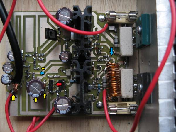
 Photo Details
|
|
|
5th element diyAudio Member Registered: October 2002 Location: England Posts: 5,267  |
Picture of the PBC. Blue arrows show feedback take off point and where the feedback joins the input stage. Yellow arrows show the signal ground points these are 1) bottom of the input filters resistor. 2) Cap from the feedback network. 3) Diode from the feedback network. 4) Ground connection from the constant current source. The red arrow shows the ground of the first transistor in the emitter follower VAS.
|
| Date: Wed January 27, 2010 |
|
| Additional Info | |
| Direct link: | |