The APx525 does support multi-tone testing and I'll be happy to take the measurements.
Hey Tom, you said this in an old thread. Can you run some multitone tests? I'd like to see also a 1khz square wave.
Might want to consider looking into different test load conditions like thiscut)
This is also a valid approach.
Hey Tom, you said this in an old thread. Can you run some multitone tests?
Already did. I provided the result in Post #252.
I also put links to the measurements in Post #1, so you can always get to them there. I'll get them up on my website when I have a bit more time. I really need to make progress on a paper I'm supposed to write for a class.
I'd like to see also a 1khz square wave.
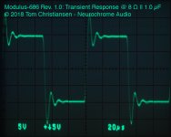
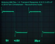
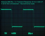
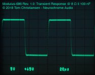
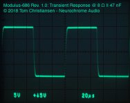
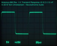
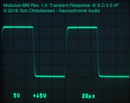
I have those. I need to annotate the pictures and get them posted. Basically, up to 8Ω||100-200nF, the amp produces a clean square wave. Past 200 nF (in parallel with 8 Ω), you'll see some ringing. That's the output inductors resonating with the load capacitance. The amp is stable but shows considerable ringing (that output LC again) at 8Ω||1uF.
I'll get the transient measurements up as soon as I can. Right now I need to focus on my education as I have been putting that off for way too long so that I could make progress on the Modulus-686. My last exam is on April 19th, so expect my schedule to clear up considerably after that.
Tom
Hi Tom
Sorry I have another possibly dumb question.
Above you stated that, past 200nF capacity load some preringing (distortion) can be observed.
Yet the article, which soongc quoted a couple of posts back, suggests a 800uF capacitor almost parallel to the amp out as part of the simulated speaker load.
Wouldn’t you expect considerable ringing with the simulated speaker load with the 686 and if not why?
Thx
SH
Ps. Sorry to keep you from studying. Good luck with your exams.
Last edited:
I have those. I need to annotate the pictures and get them posted. Basically, up to 8Ω||100-200nF, the amp produces a clean square wave. Past 200 nF (in parallel with 8 Ω), you'll see some ringing. That's the output inductors resonating with the load capacitance. The amp is stable but shows considerable ringing (that output LC again) at 8Ω||1uF.
I'll get the transient measurements up as soon as I can. Right now I need to focus on my education as I have been putting that off for way too long so that I could make progress on the Modulus-686. My last exam is on April 19th, so expect my schedule to clear up considerably after that.
Thanks. I'm absolutely not in a hurry. The modulus is 3rd on my list.
4 Ohm would be no different?
Above you stated that, past 200nF capacity load some preringing (distortion) can be observed.
Yet the article, which soongc quoted a couple of posts back, suggests a 800uF capacitor almost parallel to the amp out as part of the simulated speaker load.
800 uF would be pretty darn close to a short circuit. 10 mΩ at 20 kHz. 10 Ω at 20 Hz. I'm not aware of any speaker that looks even remotely like that. Even the electrostatic speakers aren't that capacitive.
Ps. Sorry to keep you from studying. Good luck with your exams.
Thank you. Pardon my brevity here. Now you know why.
Tom
Hi Tom
Sorry I have another possibly dumb question.
Above you stated that, past 200nF capacity load some preringing (distortion) can be observed.
Yet the article, which soongc quoted a couple of posts back, suggests a 800uF capacitor almost parallel to the amp out as part of the simulated speaker load.
Wouldn’t you expect considerable ringing with the simulated speaker load with the 686 and if not why?
Thx
SH
Ps. Sorry to keep you from studying. Good luck with your exams.
Actually there is a series resistor to the cap. Although I believe the resistor would be much less than what is in that book, which should be closer to Re of the T/S parameters.
Procrastination. It's a thing...
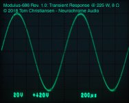
Transient plots attached. The ringing on the step response is the output inductors resonating with the load capacitance. The amplifier remains stable.
As mentioned previously, the 4 Ω transient plots are clean as well. If anything they're actually better than the 8 Ω plots as the 4 Ω load impedance dampens the LC out a bit better. I only saved the 8 Ω plots as they were the worst case.
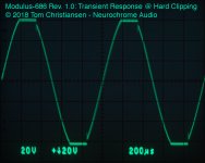
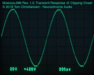
The MOD686 has the cleanest clipping response of any composite amplifier that I've seen. It does show a little bit of rail sticking as it recovers from the overload, but it is very well controlled and very short lived.
Tom
Transient plots attached. The ringing on the step response is the output inductors resonating with the load capacitance. The amplifier remains stable.
As mentioned previously, the 4 Ω transient plots are clean as well. If anything they're actually better than the 8 Ω plots as the 4 Ω load impedance dampens the LC out a bit better. I only saved the 8 Ω plots as they were the worst case.
The MOD686 has the cleanest clipping response of any composite amplifier that I've seen. It does show a little bit of rail sticking as it recovers from the overload, but it is very well controlled and very short lived.
Tom
Attachments
-
 MOD686_R1p0_HardClipping.jpg185.6 KB · Views: 200
 -
 MOD686_R1p0_ClippingOnset.jpg191.5 KB · Views: 182
 -
 MOD686_R1p0_225W8R.jpg175.7 KB · Views: 206
 -
 MOD686_R1p0_8R1u.jpg196.6 KB · Views: 213
 -
 MOD686_R1p0_8R470n.jpg193.1 KB · Views: 191
 -
 MOD686_R1p0_8R220n.jpg196.2 KB · Views: 446
 -
 MOD686_R1p0_8R100n.jpg193.2 KB · Views: 530
 -
 MOD686_R1p0_8R47n.jpg178.8 KB · Views: 527
 -
 MOD686_R1p0_8R10n.jpg186.5 KB · Views: 536
 -
 MOD686_R1p0_8R0n.jpg190.3 KB · Views: 555
Very cool. Thx.
So do I understand your two responses correctly. Because of the resistor of some 5ohms in series to the 800uF capacitor will the loudspeaker simulator circuit not cause any ring although the 800uF are much higher than the 200nF single capacitance load from your test seen above?
Thx.
Hopefully a short yes or no will suffice so you can quickly go back to your studies ;-).
Let's be clear: If the amplifier is stable with the capacitive load, the only ringing you'll see is the resonance between the output L||R network and the load capacitance. That's the case for the Modulus-686.
The case of a simulated speaker load (5 Ω + 800 uF + other components) is more complex. You're not comparing apples to apples here. 220 nF || 8 Ω is not the same load as 800 uF in series with 5 Ω. If you're truly interested, I suggest looking at how impedances work (i.e. magnitude and phase vs frequency). The point of the simulated speaker load is to get a more realistic picture of how the amp will behave with an actual speaker. Stereophile does this in their measurements and I intend to do so as well. I just need time.
In simulation, I have generally found the simulated speaker loads to be easier on the amp - at least in terms of stability. As AndrewT has pointed out more than once, the reactive loads tend to be harder on the thermal system. This is because the load line with a reactive load turns into an ellipse (for a simple reactance anyway). You can see Bob Cordell's power amp design book for more detail on that. The bottom line is: Don't skimp on the heat sink size.
So to summarize: It's complicated.
Tom
If math isn't your thing, you can easily set up a simulation to show you the impedance of 220 nF || 8 Ω vs 800 uF + 5 Ω. Just set up the two networks in a SPICE simulator (LTspice, TINA-TI, whatever), run a 1A AC current source into each of them, sweep the frequency from, say, 1 Hz to 100 kHz, and look at the voltage across the impedance. That voltage will be equal to the impedance. You'll notice that both its magnitude and phase change vs freq.
Tom
Tom
@HarmonicTHD,
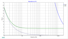
Come to think about in free XSim its very easy do the impedance simulation because its schematic window start automatic up with a power amp then dump a few components and wires and standard graph windows show component changes on the fly, in below graphs grey is that 800uF short, green is 800uF with 5 ohms in series, and blue is a 1uF short that happen up higher than X axis is able to view.
Link: XSim free crossover designer
Attachments
Modulus-686: 380W (4Ω); 220W (8Ω) Balanced Composite Power Amp with extremely low THD
Tom’s load of 8 Ohm // 1uF or less is what one would expect for speaker cable capacitance effects. It means the am will be stable under probably any long runs you may possibly use. The purpose of using a simulated speaker load is to investigate how real loading will effect amplifier distortion performance.
Tom’s load of 8 Ohm // 1uF or less is what one would expect for speaker cable capacitance effects. It means the am will be stable under probably any long runs you may possibly use. The purpose of using a simulated speaker load is to investigate how real loading will effect amplifier distortion performance.
So to summarize: It's complicated.
Tom
If it were easy, all amplifiers would sound the same
Tom’s load of 8 Ohm // 1uF or less is what one would expect for speaker cable capacitance effects. It means the am will be stable under probably any long runs you may possibly use. The purpose of using a simulated speaker load is to investigate how real loading will effect amplifier distortion performance.
Agreed. Another purpose of the simulated speaker load is to check for variation in the frequency response as function of the load.
Tom
blue is a 1uF short that happen up higher than X axis is able to view.
Which is different from the 8Ω||1uF I'm using. 8Ω||1uF should be 8Ω at DC and about 4 Ω at 20 kHz.
Tom
Thank you all for the extensive explanation and the patience explaining the difference. I got it - it would comparing apples with oranges. I even know how to use LT Spice.
Anyway, the deeper motivation of the question was (please don’t kill me over it) to find out if comparing the measure let’s say of the 286 and the 686 would show any differences in sound between two amps. They both measure very well (into pure resistive loads) yet Tom you said , the additional headroom of the 686 was somewhat audible. So I hypothesized that possibly taking measurements with a speaker simulator might reveal the differences more pronounced.
It basically comes down to the question, how come that different amps in general measure well but yet seem to sound differently? (I am not saying better, but differently). You could even compare your tube amp Tom. It measures well, doesn’t it , but sounds differently.
Again, please don’t kill me over this one, I know I am out of my area of expertise.
Thanks anyway.
SH
Last edited:
- Home
- Vendor's Bazaar
- Modulus-686: 380W (4Ω); 220W (8Ω) Balanced Composite Power Amp with extremely low THD