Thanks for the reply. I haven't opened it up yet...still. And actually after trying another amp in its place, I probably won't follow this up. Too little time, too many amps. ;-) It is a curious issue though - functioning clean sound but v little, if any, gain.
Last edited:
Cool - let us know if you find out.
I checked my psu today and it is fine - it is a 150VA toroid, 43-0-43, with a Sigma22 regulator set to +/-45V, fitted with 2x 10,000uF pre-regulator caps. I never ran the amp hard - the psu is designed for 1A continuous, with higher bursts easily managed - and the speakers are very efficient Klipsch. Perhaps +/-45V was a little too much, but the amp has not burned out - it works but little or no gain.
I checked the psu because I decided to harvest it and will use if for an LME49810 amp. I won't be trying to fix the L7.
Given the psu fully checks out, I have no idea what the problem might be.
Last edited:
Hello.
I have the Ver.1 boards (the same as in the picture of the first post).
The boards say +-50V, but in the first post ljm says 45-60V possible.
I never used them till now. But now I have built a PSU from a 2x38V transformer + 4x10.00uF.
The PSU gives 2x56-57V DC when running without load.
Connected the psu to the L15D boards. Added a Vellemann K4700 speaker protection. Put an old CD player to the inputs and 8.2Ohm 10W resistors as load on the speaker outputs.
My L15d boards show a blinking blue led (aprox 2Hz or something).
Nothing smelling, nothing smoking. Disconnected it.
Will the Ver. 1 boards not run on 57V without further modifications ?
I removed the speaker protection circuit to get rid of a possible problem from that device.
When I switch on the amp, the blue LED stays on.
I measure the DC voltage on the L15D terminals.
Between +57V and Ground the voltage rises, I shut down after 2 or 3 seconds each time. (it rises to 70-80V in this time).
Can this be caused when Rev1 boards are fed with 55-57V instead of suggested 50V ?
Hello!
I just finished build 2 x L15D and put it to case.
I connected speaker to left channel and turn on amp.
Green LEDs(from kit) start lighting and after 30 seconds I got BOOM and smoke.
Burned 10R(R21) 10K(R23) 20R(R24) names from Iraudamp7s schematic.
Also 4019 D669 IRS2092 damaged.
Then I disconnect left channel and turn on AMP and got same damages with right channel.
I checked all diodes orientation, resistors values and connections. Everything correct.
What could be wrong and Can i get it because install Green leds?
Hello LJM,
Where can I purchase this amplifier?
There should be some agency can buy.
The amplifier is not expensive.
Because of its width is a little big, is not convenient to install.
I put it a slightly adjusted,
Attachments
please, sir ljm - will this one be available some day?
and if, do you recommend combining it with your preamp nr. 9?
thank you very much...
L20.5 can match any preamp.
If L20.5 PREAMP9 collocation, can be GAIN magnification to reduce some.
Such as 330 r resistance changes for 470 r. So the volume won't appear too big.
But also can reduce some distortion. Basically can achieve 0.007% THD + N
, of course, also can use more simple and convenient P7MINI,, P8 OP PREAMP
Hello, LJM!
I've ordered one kit from ZOE_TSANG yesterday:
L20.5 200 Вт + 200 Вт HiEnd 0.0015% AP КЭК KTB817 KTD1047 усилитель комплект купить на AliExpress
How do you think, will they send me old design or the new one?
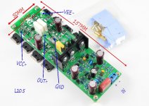
And what is it a big yellow parallelepiped means?
I've ordered one kit from ZOE_TSANG yesterday:
L20.5 200 Вт + 200 Вт HiEnd 0.0015% AP КЭК KTB817 KTD1047 усилитель комплект купить на AliExpress
How do you think, will they send me old design or the new one?
And what is it a big yellow parallelepiped means?
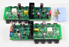
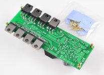
Hello, I don't about "big yellow parallelepiped", but parallel probably refers to the output section of this amp, which has 4 pairs of transistors in CFP parallel configuration. I have not seen that on any other design, usually CFP outputs has only one or two pairs. From the pictures, I can see that LJM has used emitter resistors for each device, for better load/current sharing, but they all go through the same two output resistors.
I expect the amplifer is similiar to Doug Self's "Load-Invariant" design, but with double the output transistors. Or perhaps more accurately, this looks quite similar to an MX50SE, but with x4 the output devices")
I expect the amplifer is similiar to Doug Self's "Load-Invariant" design, but with double the output transistors. Or perhaps more accurately, this looks quite similar to an MX50SE, but with x4 the output devices
Thank you for your reply, jvhb.
I think that big yellow cubic on a new design is a capasitor that substituted a pink one on old design (part of Zobel circuit).
Output stage should be like that of L12-2
http://www.diyaudio.com/forums/solid-state/196089-l12-2-cfp-output-amp-120w-2-8r-2.html#post3373053
but with 4 pairs of output transistors and emitter resistors = 0,05 Om.
Input and VAS stages a mysterious for me, because they have only 6 small transistors and 2 very small chips. Are they current sourses or current mirroros chips?
Thank you for your reply, jvhb.
I think that big yellow cubic on a new design is a capasitor that substituted a pink one on old design (part of Zobel circuit).
Output stage should be like that of L12-2
http://www.diyaudio.com/forums/solid-state/196089-l12-2-cfp-output-amp-120w-2-8r-2.html#post3373053
but with 4 pairs of output transistors and emitter resistors = 0,05 Om.
Input and VAS stages a mysterious for me, because they have only 6 small transistors and 2 very small chips. Are they current sourses or current mirroros chips?
I think the meaning of the amplifier is not directly comparable
Such as L12-2. We don't change the PCB. Only replace all of the components.
It will be a completely different effect.
So I pay more attention to the results of sound. Rather than its circuit structure. The same structure, performance indicators may be one hundred times the gap.
L20.5 better than L12-2 significantly out of a piece. Because they use similar circuit.
But it is not the voice of the same style. B: yes.
Not the same. Better results.
We don't need too much study the structure of the circuit.
May be just a resistance value is different. Ten times will bring the performance difference.
Hello, I don't about "big yellow parallelepiped", but parallel probably refers to the output section of this amp, which has 4 pairs of transistors in CFP parallel configuration. I have not seen that on any other design, usually CFP outputs has only one or two pairs. From the pictures, I can see that LJM has used emitter resistors for each device, for better load/current sharing, but they all go through the same two output resistors.
I expect the amplifer is similiar to Doug Self's "Load-Invariant" design, but with double the output transistors. Or perhaps more accurately, this looks quite similar to an MX50SE, but with x4 the output devices
I think it is not complicated. Actually I have been using this output structure more than ten years.
And I used almost known now, all structures.
And the actual measurement comparison.
I can think L20.5 transcend all DIY exist. Of course. This is just my fantasy.
In fact, there are many many DIYER. Have gone through a lot of machines. Manufacturer of machine contrast effect.
Attachments
Hello, I don't about "big yellow parallelepiped", but parallel probably refers to the output section of this amp, which has 4 pairs of transistors in CFP parallel configuration. I have not seen that on any other design, usually CFP outputs has only one or two pairs. From the pictures, I can see that LJM has used emitter resistors for each device, for better load/current sharing, but they all go through the same two output resistors.
I expect the amplifer is similiar to Doug Self's "Load-Invariant" design, but with double the output transistors. Or perhaps more accurately, this looks quite similar to an MX50SE, but with x4 the output devices
Attachments
-
 111039blnxzp7eavnh270l.jpg129.1 KB · Views: 407
 -
 111038r5sthttkt6sjaxfv.jpg142.7 KB · Views: 406
 -
 111036jpjyj6nfrzpvk9fc.jpg129.9 KB · Views: 326
 -
 111035rpaz20d2dzeeno8l.jpg143.1 KB · Views: 829
 -
 111034sb72e7dbj7a27elj.jpg123.1 KB · Views: 838
 -
 111034oxvyqan9yvy8vcax.jpg141.6 KB · Views: 858
 -
 111033awoiasss1lbowxv1.jpg146.3 KB · Views: 871
Hello, I don't about "big yellow parallelepiped", but parallel probably refers to the output section of this amp, which has 4 pairs of transistors in CFP parallel configuration. I have not seen that on any other design, usually CFP outputs has only one or two pairs. From the pictures, I can see that LJM has used emitter resistors for each device, for better load/current sharing, but they all go through the same two output resistors.
I expect the amplifer is similiar to Doug Self's "Load-Invariant" design, but with double the output transistors. Or perhaps more accurately, this looks quite similar to an MX50SE, but with x4 the output devices
MX50SE L12-2 L20.5 of CFP structure has been adopted.
But their performance. Voice. It is not the same.
As 90% of the world's power amplifier using E output stage, but they are not similar sounds or performance.
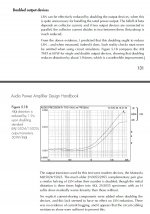
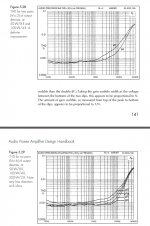
The parallel power tube, for the influence of the output stage can be reference: Audio Power Amplifier Design Handbook On page 131-141。
SELF in tests confirmed that 6 parallel pipe distortion is less than 2 parallel, 2 is less than the power tube in parallel.
And equally effective in CFP structure. Please find in the book. I remember the CFP there is 6 for tests and comparative data of the tube.
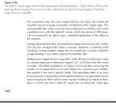
《On a practical note, the more output devices you have, the harder the
amplifier may be to purge of parasitic oscillations in the output stage. This
is presumably due to the extra raw transconductance available, and can be
a problem even with the triple-EF circuit, which has no local NFB loops.
I do not pretend to be able to give a detailed explanation of this effect at
the moment.》
So I do not recommend amateur use too much of transistors in parallel.
Because of this design is very unstable. Need professional measuring instrument. And need to the practical application of feedback for a long time. To correct all kinds of stability in the environment is used.
Attachments
Last edited:
@ljm_ljm
Two questions:
* SNR "A weighted" at 1 watt?
* harmonic profile at 1 watt and 10 watts? H2, H3, H4 dB
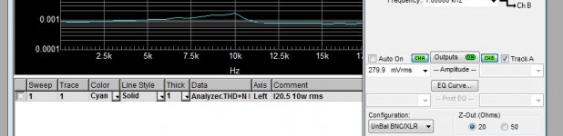
O. In fact, I don't remember the test already. But I want to open a computer store information.
I saw the test, the INPUT INPUT signal is 280 mv RMS, 396 m VP
GAIN = 31
The output voltage should be 0.28 * 31 = 8.68 V RMS
8.68 * 8.68/8 = 9.41 W
Precisely 9.41 W.
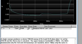
If you need accurate power - THD test pattern.
You can refer to the first page of the THD + N VS FREQUENCY
Attachments
- Home
- Vendor's Bazaar
- LJM Audio