Today I had fireworks and a bonfire from one of these, most of the pre-driver transistors exploded, the output fets are toast. This is running off +/- 35V unstabilised and a large heatsink. The heatsink didn't get hot either.
There are some kits available which appear to have several output fets in parallel, anyone tried one?
There are some kits available which appear to have several output fets in parallel, anyone tried one?
Some news with my L15D boars. I change IRS2092 and 4091 mosfet but the issue is not resolved.
I made some test with the boards. It seems that the working board PWM signal is 460kHz and the other one only 440kHz.
Something is wrong with this one but I can't find why.
Did you change both mosfets ?
Quite often a mosfet blowing will take out 2092 as well.
Did you change both mosfets ?
Quite often a mosfet blowing will take out 2092 as well.
There is only one mosfet 4019H on my board, it's the non pro version. I noticed also that the PWM resistor is 300ohm. I will try with 270ohm as LJM said.
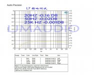
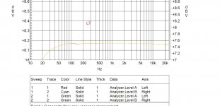
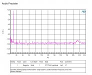
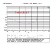
L7 Frequency response test
Hello LJM,
I am a happy purchaser of several pair of L7's and an L 20 pair too.
Tried them in various forms, integrated amp, mono and stereo power amps and even biamplification.
When given the right solutions, those little amps are able to outperform some of the most estimated giants of the audio market.
As David Church remarked as well, the only problem is that it is not possble to go beyond 29-0-29V trafo wanting to keep a safe operation.
Whenever I tried to use a 36-0-36 V trafo both the NCC 5551 and 5401 pairs close to the output devices burnt at once.
The output pairs instead kept in working order.
It sounds strange, especially seeing that the lytics near the outputs are rated at 80V, that should be a bit more than the voltage the designer expected the amp could bear.
Is there a solution to exploit all of the potential of these little beasts with an adequate power supply voltage?
Thank you.
Last edited:
Hello LJM,
I am a happy purchaser of several pair of L7's and an L 20 pair too.
Tried them in various forms, integrated amp, mono and stereo power amps and even biamplification.
When given the right solutions, those little amps are able to outperform some of the most estimated giants of the audio market.
As David Church remarked as well, the only problem is that it is not possble to go beyond 29-0-29V trafo wanting to keep a safe operation.
Whenever I tried to use a 36-0-36 V trafo both the NCC 5551 and 5401 pairs close to the output devices burnt at once.
The output pairs instead kept in working order.
It sounds strange, especially seeing that the lytics near the outputs are rated at 80V, that should be a bit more than the voltage the designer expected the amp could bear.
Is there a solution to exploit all of the potential of these little beasts with an adequate power supply voltage?
Is there an accurate schematic of these amps, to try an LTSpice simulation? Perhaps it's possible to see what's the problem there.
For instance, the one you assembled and had those transistors burn on you.
Is there an accurate schematic of these amps, to try an LTSpice simulation? Perhaps it's possible to see what's the problem there.
For instance, the one you assembled and had those transistors burn on you.
Hi Carlmart,
thank you for your help.
This is the L7 schematic I have.
Hope it can do.
An externally hosted image should be here but it was not working when we last tested it.
Last edited:
Hi,
After I asked for the schematic, I went have a look at the other pages.
That schematic has some errors on the gain values, which should be inverted: 10K/330.
What are the voltages you are using, and where did it get unstable for you?
Now I am using a 29-0-29V trafo and have safe operation.
When I tried a 36-0-36V, the 5551 and 5401 pairs closer to the output exploded at switch on.
I'll make yet another power supply!
Trying one of LJM's older amplifiers well outside the audio range, there were some large spikes appearing in the signal from time to time which would then take out the output transistors. I had modified the Zobel output network to suit the frequency so "Mea Culpa".
I changed the transistors to some 250V types and the problem has not recurred.
I didn't hook the scope up on this newer amp because it seemed very satisfactory to start with.
Hi Carlmart,
thank you for your help.
This is the L7 schematic I have.
Hope it can do.
An externally hosted image should be here but it was not working when we last tested it.
Do you know the output mosfets symbols are inverted, don't you?
Do you know the output mosfets symbols are inverted, don't you?
I just followed the printing on the board supplied with the kit, that is correct.
Anyway the NCC 5551 has a different contact scheme than the 2N 5551 available on western markets
I just followed the printing on the board supplied with the kit, that is correct.
Anyway the NCC 5551 has a different contact scheme than the 2N 5551 available on western markets
I don't know what's on the board. What I say is that the IRFP240 symbol is wrong, with the arrow going the wrong direction. Have a look at the pdf:
http://www.irf.com/product-info/datasheets/data/irfp240.pdf
I don't know what's on the board. What I say is that the IRFP240 symbol is wrong, with the arrow going the wrong direction. Have a look at the pdf:
http://www.irf.com/product-info/datasheets/data/irfp240.pdf
You have been so careful to discover another mistake on the L7 schematic diagram.
")
Maybe someone could redraw it to have finally a reliable one.
Dear LJM
I tried to contact you via PM. Anyway, is this board made by you ? IRS2092S 500W Mono Channel Digital Amplifier Class D HIFI Power Amp Board + FAN | eBay
All blame where I live is not cheap, convenient international logistics.
So I didn't open the EBAY. Usually there will be some agency business in my buy here.
Usually it's not a problem. Just the price may change. Specific I also don't know.
You can refer to my taobao is introduced. With detailed information.
404 Not Found
- Home
- Vendor's Bazaar
- LJM Audio