Alan, it's been a while, are you listening to the LDRs yet?
Hi Karl, i had a chance yesterday for a bit, i programmed my logitech harmony for a sony tv and it automatically did balance too, I guess the model I picked must work their VCRs aswell, result. I absolutely love it, having this level of performance and been able to control it from my seat just puts a big smile on my face.
 As far as Im concerned thats the winner for me, they can argue all day about how resistors are more accurate and everything else is coloration, well I dont care, I love the sound my system is making.
I stuck a movie on after playing some tunes and I got a bit of a shock, I had to turn down the plate amps because my radiator started to rattle big time!!, the bass was way too much so it looks like there is a lot more gain or bass from my home brew amp even though i think the specs are very similar on paper for the 3116 amp. I need to adjust the levels on my AV amp now so I can balance the bass back up, it took me ages to get to a happy level, too many adjustments on my setup.
I have a couple of requests if possible? When im watching Movies/TV the OLED display is distracting me a weeee bit, i could put a dark cloth over it but what would be really good is an AV bypass function on your new input switch, I dont need the LDR for Movies, I set the volume at 99 and use the front L/R pre outs on the AV amp, i am probably asking too much but an ideal situation would be an input on my amp that shuts off the display and bypasses any attenuation, is this possible? I think an AV bypass would actually be a good feature anyway, possibly even an added selling point?
Anyway ive got an hour now to set my system back up again, i still havnt tried my plate amps connected to the line level of the DCB1, they are on speaker inputs running direct off the back of the chip amps, ive been avoiding it but it seems i am going to have to do some setting up anyway. I will try and get some serious listening in but If I ever change anything else it wont be my volume control.
Hi Karl, i had a chance yesterday for a bit, i programmed my logitech harmony for a sony tv and it automatically did balance too, I guess the model I picked must work their VCRs aswell, result. I absolutely love it, having this level of performance and been able to control it from my seat just puts a big smile on my face.
I stuck a movie on after playing some tunes and I got a bit of a shock, I had to turn down the plate amps because my radiator started to rattle big time!!, the bass was way too much so it looks like there is a lot more gain or bass from my home brew amp even though i think the specs are very similar on paper for the 3116 amp. I need to adjust the levels on my AV amp now so I can balance the bass back up, it took me ages to get to a happy level, too many adjustments on my setup.
I have a couple of requests if possible? When im watching Movies/TV the OLED display is distracting me a weeee bit, i could put a dark cloth over it but what would be really good is an AV bypass function on your new input switch, I dont need the LDR for Movies, I set the volume at 99 and use the front L/R pre outs on the AV amp, i am probably asking too much but an ideal situation would be an input on my amp that shuts off the display and bypasses any attenuation, is this possible? I think an AV bypass would actually be a good feature anyway, possibly even an added selling point?
Anyway ive got an hour now to set my system back up again, i still havnt tried my plate amps connected to the line level of the DCB1, they are on speaker inputs running direct off the back of the chip amps, ive been avoiding it but it seems i am going to have to do some setting up anyway. I will try and get some serious listening in but If I ever change anything else it wont be my volume control.
Hey, that's great news! So glad it's finally come together. It sounds like your reaction to the quality of the sound is the same as mine was when I got my first prototype working and heard LDRs for the first time. It was like layers of veil were taken away and my emotional connection to the music was hugely enhanced.
Regarding your wishes for bypassing the LDR control so the display is turned off, it seems to me that if it is the brightness is what you're objecting to, we might add a menu item so that you could manually choose between causing the volume level to move around the display after a period of time, and turning it off entirely or create a user-selectable level of brightness. Understand, these are ideas that perhaps can be implemented and I'm not making any promises. I do think it would be easy to set it up to come back on automatically when any control input is sent via IR remote or front panel control knob.
Alternatively, if you want to entirely bypass the LDR control and send input signal direct to an outboard amplifier, I think you would want to install a high input impedance buffer so as to avoid loading the circuit and changing the LDR resistance curves, and thus take the signal from before the LDRs and output it through a separate set of RCA sockets. Actually, the direct out RCAs have been in the plan for a while and you could use my implementation to do what you are thinking of doing.
I think I'm just about ready to get back to working on the programming and the input selector board. Tell me if I've understood what you want or if I got it wrong.
Any progress on the input board (post#60)?
Really interested in this preamp but need 4 (single ended) analogue inputs.
Tim
Before we moved to a new house I had a prototype that I was working with. During the move I stopped active work but kept on thinking about how to implement an input selector system. I think I've got a much better handle on the requirements now than I did originally, so when I sit down to put the design into a CAD drawing it should go pretty fast. We shall see.
Hey, that's great news! So glad it's finally come together. It sounds like your reaction to the quality of the sound is the same as mine was when I got my first prototype working and heard LDRs for the first time. It was like layers of veil were taken away and my emotional connection to the music was hugely enhanced.
Regarding your wishes for bypassing the LDR control so the display is turned off, it seems to me that if it is the brightness is what you're objecting to, we might add a menu item so that you could manually choose between causing the volume level to move around the display after a period of time, and turning it off entirely or create a user-selectable level of brightness. Understand, these are ideas that perhaps can be implemented and I'm not making any promises. I do think it would be easy to set it up to come back on automatically when any control input is sent via IR remote or front panel control knob.
Alternatively, if you want to entirely bypass the LDR control and send input signal direct to an outboard amplifier, I think you would want to install a high input impedance buffer so as to avoid loading the circuit and changing the LDR resistance curves, and thus take the signal from before the LDRs and output it through a separate set of RCA sockets. Actually, the direct out RCAs have been in the plan for a while and you could use my implementation to do what you are thinking of doing.
I think I'm just about ready to get back to working on the programming and the input selector board. Tell me if I've understood what you want or if I got it wrong.
If the input buffer is only on one input then that sounds like a good idea but if its an additional circuit that all the inputs go through which im guessing is the only way to do it, I would say just turn off the display. It would be amazing if it was an IR command to turn it off and switch to AV input, then I could program my Logitech to set it all up on an activity which is just one button push for my girlfriend.
I can add extra vol up commands to the activity so the amp is at 99 then send a command to switch the display off. Having the display shut off automatically also works for me. Season's Greetings!
It's been a long wait, but we're finally settled in our new digs and I've completed the hardware and software designs for an input selector board that complements the other boards in the system. Function is verified and a small run of boards are on order.
It's diminutive and will fit in very small enclosures -- see the drawing -- and signal traces are very direct from four inputs to a single output. Left ground and right ground are kept separate throughout, and all signal and signal ground tracess are isolated from power and control ground.
The relays are the telecom hermetically sealed "latching" type -- contacts will never be contaminated and they draw only 19ma for a mere 50 milliseconds when an input is switched, and otherwise draw no current at all which means no magnetic field during operation.
The selected Input will be displayed on the OLED -- a large digit momentarily when a new input is selected, and then smaller text to the side of the large volume display during operation. It is now possible to build a complete passive LDR preamp with BTFSystems components.
We are closed over the holidays, hope to offer the input selector board early in the new year.
Attachments
Hi is there a way to connect two LDR boards to one controller module for balanced input?
I have been asked that a number of times, I need to make that happen. Currently, there is not but it should be doable. Controlling the volume on two boards should be quite easy, but the display has other functions like displaying current levels in the LDRs and showing calibration percentage completed. These would be difficult to modify to show data from two boards.
I have just finished the hardware and software for a 4 way input selector board, so it's a good time to look at making the controller work with two LDR boards. I'll look into that early in the new year.
That would be a great news and looking forward to it! I like the simplicity of your design as calibration are done individually on each LDR boards.
Right now I think I would like to get 2 LDR boards and to control with pots for my balanced preamp, but I don't see price listed on your website.
Right now I think I would like to get 2 LDR boards and to control with pots for my balanced preamp, but I don't see price listed on your website.
That would be a great news and looking forward to it! I like the simplicity of your design as calibration are done individually on each LDR boards.
Right now I think I would like to get 2 LDR boards and to control with pots for my balanced preamp, but I don't see price listed on your website.
I've looked at my code and it appears that I can make changes that will allow the RE/IR board to control volume levels of two LDR boards and make the balance work between the boards instead of between the channels of one board.
Also looks like I can keep the LDR milliamp display intact and also track calibration percentage complete for two boards. The milliamp display would display the two highest milliamp readings instead of all four milliamp values, and the calibration percentage would display the percentage complete of the board that has the longest to go before completion. The "Calibration Complete" screen would appear when both boards were fully calibrated.
The reason you don't see any prices on my website is because I've been contemplating shifting from selling individual components to selling complete systems. Still, I'm getting a lot of requests for the LDR board only and for LDR boards for balanced systems as well as the occasional 5.1 system, so I'm now thinking instead of breaking the system into two parts -- LDR board being one, the other being the complete RE/IR board, display, and rotary encoder. By doing this, I could lower the combined price of the RE/IR & display components somewhat.
I need some information on what a balanced system volume control should look like -- I assume four audio-curve potentiometers, but what is the optimal value of each pot? Is there a "standard" value or a typical value? I can go from 5K to about 90K where control of the LDR becomes very challenging due to the extremely low current required to hold it at that value. 100K would be unreliable.
That would be a even greater news seems it will not be a harsh task for you to modify the codes, but guess I would have to wait until you settled the selling plan. It makes sense to sell the LDR boards individually and the other being the complete RE/IR board, OLED, and RE.
I believe a balanced volume control would be simply a four-gang pot and there is no typical value for all applications, which the value should highly depends on the source.
I believe a balanced volume control would be simply a four-gang pot and there is no typical value for all applications, which the value should highly depends on the source.
How does one get more details and pricing, including shipping to Bangalore, India.
Thanks,
Samuel, I apologize for the delay in responding to you. I will shortly be modifying my website with new information that will answer your questions. Watch the website or watch this thread for updates.
I have finished testing the function of my prototype Input Selector, and it works as expected.
It is a 4-way selector that uses latching, hermetically-sealed telecom-quality relays to control the input.
The latching is significant for a number of reasons:
First, the coil is energized only when actual switching is taking place, and only for about 50 milliseconds. After that the current through the coil drops almost to zero and the magnetic field dissipates. This means that there is no magnetic field in the vicinity of the audio signal.
Second, this board draws very little power. The 8-pin DIP chip is the only full-time consumer of current; when a relay switches there is a momentary draw of about 19 milliamps, again for that 50 milliseconds only.
The circuit, like all of the BTFSystems boards, is designed with simplicity as a main goal that is second only to quality and reliability of operation. The circuitry consists of one IC, six capacitors, and four relays, that's all. Protective diodes are not required for this circuit because the magnetic field does not "collapse" as it would with a conventional relay -- it gracefully reduces over a period of time with no voltage spike of any kind.
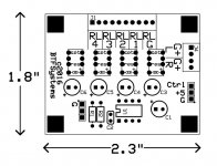
The board, at 2.5 x 1.9 inches is slightly larger than the final board which will be 2.3 x 1.8 inches. This is a small board that will fit almost anywhere.
Control and power is taken from the display, and is delivered via a simple 3-wire premade cable which is available in various lengths from any hobby store selling remote-control servos and vehicles.
Control is via the Sony TV-compatible remote control -- pressing digit buttons 1~4 results in the input switching to that input number.
Input is via a 10-terminal .1" terminal strip -- one terminal per signal line plus one terminal each for left channel ground and right channel ground. Channel grounds are kept separate from each other throughout, and also separate from the system ground plane.
Output is via a 4-terminal .1" terminal strip -- one terminal each for left and right signal and left and right ground.
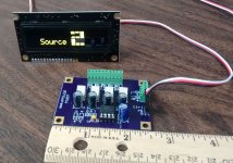
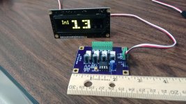
The attached photos show the board and display; one picture shows the display as a selection is made, with a large digit showing the selection, the other picture shows the normal display with volume in large digits and the Input number display in smaller digits to the side. When the display has LDR milliamps turned on, the input number moves to the lower line. It is always visible except when both milliamps and Balance offset values take up both the top and bottom lines.
A number of folks have asked for a switching capability to go along with the LDR volume control, I hope this will be a good solution for you.
It is a 4-way selector that uses latching, hermetically-sealed telecom-quality relays to control the input.
The latching is significant for a number of reasons:
First, the coil is energized only when actual switching is taking place, and only for about 50 milliseconds. After that the current through the coil drops almost to zero and the magnetic field dissipates. This means that there is no magnetic field in the vicinity of the audio signal.
Second, this board draws very little power. The 8-pin DIP chip is the only full-time consumer of current; when a relay switches there is a momentary draw of about 19 milliamps, again for that 50 milliseconds only.
The circuit, like all of the BTFSystems boards, is designed with simplicity as a main goal that is second only to quality and reliability of operation. The circuitry consists of one IC, six capacitors, and four relays, that's all. Protective diodes are not required for this circuit because the magnetic field does not "collapse" as it would with a conventional relay -- it gracefully reduces over a period of time with no voltage spike of any kind.
The board, at 2.5 x 1.9 inches is slightly larger than the final board which will be 2.3 x 1.8 inches. This is a small board that will fit almost anywhere.
Control and power is taken from the display, and is delivered via a simple 3-wire premade cable which is available in various lengths from any hobby store selling remote-control servos and vehicles.
Control is via the Sony TV-compatible remote control -- pressing digit buttons 1~4 results in the input switching to that input number.
Input is via a 10-terminal .1" terminal strip -- one terminal per signal line plus one terminal each for left channel ground and right channel ground. Channel grounds are kept separate from each other throughout, and also separate from the system ground plane.
Output is via a 4-terminal .1" terminal strip -- one terminal each for left and right signal and left and right ground.
The attached photos show the board and display; one picture shows the display as a selection is made, with a large digit showing the selection, the other picture shows the normal display with volume in large digits and the Input number display in smaller digits to the side. When the display has LDR milliamps turned on, the input number moves to the lower line. It is always visible except when both milliamps and Balance offset values take up both the top and bottom lines.
A number of folks have asked for a switching capability to go along with the LDR volume control, I hope this will be a good solution for you.
Attachments
Last edited:
Dear Wapo,
is your system able to target high impedances too?
And if you stopped to sell them, can you please share how you managed to linearize the curve and get stable results on high impedances?
I tried to do it years ago, but 16 bit pwm wasn't enough to control the high impedance (where there's high gradient on the curve and low precision on the pwm control).
Thank you in advance,
Kind Regards
- Status
- This old topic is closed. If you want to reopen this topic, contact a moderator using the "Report Post" button.
- Home
- Vendor's Bazaar
- BTFSystems precisionLDR modules for digitally-controlled LDR Passive Preamp