It is definitely technically possible from a hardware perspective - provided such a stream is input exists. For the BBB this would mean a properly configured driver - not sure such a driver exists. I don't think the Amanero supports that.
The Cronus itself will not convert I2S or anything else to such a signal.
The Cronus itself will not convert I2S or anything else to such a signal.
Hi Russ,
I have BBB-> Hermes -> Chronus -> BIIIse as per the picture.
My clocks are 45/49. Everything is working correctly except for the fact that I have to put the clock divider in 1:1. When switching to 1:2 (or even 1:4) then I don't get lock.
I saw zz1969 had a similar problem:
I checked and re-solded just in case J1:2 without success. Do you think the divider could be dead as well?
Thanks
I have BBB-> Hermes -> Chronus -> BIIIse as per the picture.
An externally hosted image should be here but it was not working when we last tested it.
My clocks are 45/49. Everything is working correctly except for the fact that I have to put the clock divider in 1:1. When switching to 1:2 (or even 1:4) then I don't get lock.
I saw zz1969 had a similar problem:
Yep, I guessed that. I will check. If the divider is dead what is the next step, I wonder? Can it be repaired or the setup needs a new Cronus?
I checked and re-solded just in case J1:2 without success. Do you think the divider could be dead as well?
Thanks
Now, it's time for optimisation ... I'm going to build the power supplies. Is there any requirement for the sequence of the supplies that needs to be applied to the different elements ? for example, BBB first and then Hermes, then Cronus then DAC ? Or maybe, it could be in any order ?
Any recommendation ?
Many thanks for any help !
Any recommendation ?
Many thanks for any help !
Sounds like two seperate problems.
If you have access to a scope the best thing would be to check for the presence of the correct clock on the Hermes header for each jumper position.
An update before checking with the scope tomorrow:
I tested switching the jumper to 1:4 and... Bingo! Everything was working perfect with signals from 44.1 Khz to 384Khz. Not sure I express mself clearly in my previous post, but setting the jumper to 1:1 I was getting lock and sound, but everything was way too fast. When switching to 1:2 the signal was not even locking.
I was under the impression that the correct configuration was with 1:2. Did I miss something? Is this correct?
I did some measurements on the 3 jumper positions (J1:1, J1:4 and J1:2) using my old scope:
J1:1 This measurement is almost in the limit for my 50Mhz scope, but we can see a signal of approximately 50Mhz (each division 0.02 uS for all measurements)
J1:4 Here we can measure approximately 25Mhz, which is surprisingly the half of the frequency from J1:1
J1:2 This one seems totally wrong
An externally hosted image should be here but it was not working when we last tested it.
J1:1 This measurement is almost in the limit for my 50Mhz scope, but we can see a signal of approximately 50Mhz (each division 0.02 uS for all measurements)
An externally hosted image should be here but it was not working when we last tested it.
J1:4 Here we can measure approximately 25Mhz, which is surprisingly the half of the frequency from J1:1
An externally hosted image should be here but it was not working when we last tested it.
J1:2 This one seems totally wrong
How to remove XO trident?
Can anyone explain this in more detail please? I have a B3. I can't figure how to remove XO trident.
Thanks,
Doug
You must always remove the XO trident if you use an external clock. You don't do anything with the XO itself - leave it alone.
For dual mono with B3 or B3SE I would suggestion async mode (just leave Buf configured normally with XO trident) - but if you go synch you need to route the master clock to both DACs.
In any case for dual mono you just route all signals (except MCK if going async) to both DACs.
Can anyone explain this in more detail please? I have a B3. I can't figure how to remove XO trident.
Thanks,
Doug
I'm going for async mode. Do I need to remove XO trident?
No, you only need to do that for synchronous mode.
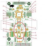
See the attached picture. Just pull the trident regulator labelled VDD_XO. I've circled it in red.Can anyone explain this in more detail please? I have a B3. I can't figure how to remove XO trident.
Thanks,
Doug
---Gary
Attachments
You can connect it directly, check this picture of B3+Cronus:
http://bbb.ieero.com/cronus-hermes-bbb.small.jpg
http://bbb.ieero.com/cronus-hermes-bbb.small.jpg
- Home
- More Vendors...
- Twisted Pear
- Cronus - It's about time.