Which resistors for Cronus
Hello
As I said in another thread, I didn't get the resistors for the Cronus in the package I've received.
I will get them here in France, but I need to know what I have to buy.
I understood their values is 33R, but I don't know which characteristic is important (precision, SMD/normal, noise). Any advice is welcome !
One more question : should I solder all resistors if I only use stereo ?
Many thanks in adavance for your help,
Cheers
Pascal
I can send you the missing resistors.
The kit comes with standard 1% metal film in both through hole and SMD.
RNMF14FTC33R0 Stackpole Electronics Inc | S33CACT-ND | DigiKey
ERJ-6GEYJ330V Panasonic Electronic Components | P33ATR-ND | DigiKey
Power requirements are minimal. 0.125W is plenty.
Some questions
Guys,
Just to clarify a few things before I start soldering, hope you can help out with my questions below.
My DAC (ES9016) already has an I2S isolator on board and expects the following signals:
- I2S Word Clock (a.k.a. frameclock) == DSD Data1 --> This connects to D1 on Cronus?
- I2S Data == DSD Data 2 --> this connects to D2 on Cronus?
- I2S Bit Clock == DSD Clock --> this connects to DCK on Cronus?
In addition my DAC expects a 3v3 (would work with 5v0) and a GND from the I2S source. This connects to VD and GND on Cronus?
Some other questions:
1. where would I now feed 5v0 to Cronus, this as my DAC does not supply it?
2. MCK and CS OUT are only necessary when doing clock sync with the DAC?
3. When to use O_D8 and O_D7?
4. When to use EX1 and EX2?
5. If my DAC only expects BCK, D1, D2 and GND; am I right that I only have to use R5 to R7?
Apologies if something duplicates what has been discussed earlier but I could not find it using the search engine.
You must always remove the XO trident if you use an external clock. You don't do anything with the XO itself - leave it alone.
For dual mono with B3 or B3SE I would suggestion async mode (just leave Buf configured normally with XO trident) - but if you go synch you need to route the master clock to both DACs.
In any case for dual mono you just route all signals (except MCK if going async) to both DACs.
Still have problems connecting Cronus to BIIISE. Goal - stereo BIIISE with Cronus and BBB/Hermes.
On BIIIse side:
1. Removed Trident XO (BIIIse clock switched off in this case?)
2. Jumpered IPS
3. All SW1 and SW2 to ON
On Cronus side:
1. Direct cabling: DCK to DCK, D1 to D1, D2 to D2, uFL U-MCK to uFL Ext-MCK on BIIISE
2. VD and GND to VD and GND on BIII
3. only R5-R7 populated
J1:1 signal locks, music plays very fast
J1:4 signal cannot lock but I can hear clock, led blinks
J1:2 signal doesn't lock
What am I doing wrong? Can anyone advise, please?
I'm confused by the "disable" jumper option.Make sure the disable jumper on the clock divider is open.
If I eventually use 22/24Mhz clocks, then the "1:1" jumper setting would seem correct,
but does "disable" mean the clock signal passes through, and this is what I should use instead?
No success so far.
1. DPLL wide open
2. J 1:2
3. Made signal and MCK cables short (2 inch)
same story -
J 1:2 - no lock
J 1:1 - good lock
Maybe I should check something in Botic?
Do you have access to a scope? It sounds like may have a dead clock divider. This can happen if it's output signals got shorted. Please also double check all solder joints to pads.
Last edited:
") We will get you sorted.
We will get you sorted.Hello
I want to connect the BBBK/Hermes/cronus to a DAC based on PCM5102 (from DIYINHK).
I need to know how to connect I2S to the Cronus. I've tried to search in this forum, but can't get any clear answer.
Can anyone tell me where are the following signals on the Cronus :
I2S BitClock : ?
I2S WordClock (or LeftRightClock) : ?
I2S DataLine : ?
I2S MasterClok : I guess this is MCK
Many thanks in adavance for your help
Cheers,
Pascal
Thanks.The disable jumper merely powers down the divider when it is not being used. The 1:1 position does not pass through the divider at all.
Another 2 questions, please, regarding the battery. I intend to buy a LiPo battery with NTC lead, and I see that the "NTC" connection on the Hermes board has a resistor to GND, which I measure to be 10k. But 10k is not the value specified in the TPS65217C datasheet -
By default, the device is setup to support a 10 kOhm NTC with a B-value of 3480. The NTC is biased through a 7.35-kOhm internal resistor connected to the BYPASS rail (2.25 V) and requires an external 75-kOhm resistor parallel to the NTC to linearize the temperature response curve.
The datasheet also specifies a 10 uF capacitor across the BAT+ connection to GND.
Q1. should the resistor value be 75k instead of 10k?
Q2. should there be a 10 uF cap across the battery connection?
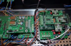
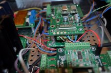
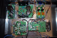
I'd love to see some close-up pictures of BIIISE coupled to Cronus from different angles. Can anyone do it, please?
Hi,
Here are some pictures of my B3SE setup with Hermes/Cronus.
Attachments
- Home
- More Vendors...
- Twisted Pear
- Cronus - It's about time.