Hi hkminn,
Interesting approach!
The Sowter datasheet suggests that the IV resistor may also be used across the secondary winding of the transformer (taking into account that the value of the resistor is reflected on the primaries by the ratio of the transformer (18.7) squared: 18.7 x 18.7= 350). Did you try that also?
What are the drawbacks of the high transform ratio? Or is there something like a free lunch?
Datasheet for Sowter 8347 and 9055:
Sowter Type 8347 DAC INTERFACE TRANSFORMER
Peter
Hi Peter,
I have not tried I/V resistor on the secondary yet. I was trying Joe's suggestion, and carried away a little bit ending up using 1R resistors.
The reason why I picked 8347 was just because I happen to have one. But the high ratio(1:17) turns out to be an advantage to me. Since 8347s have a quite amount of gain, I could use a lower value resistor and lower-gain tube stage. It is a sure advantage for DIYers.
Soundwise, I have not done much comparison yet, but I definitely prefer this approach to the opamp virtual ground I/V.
Hi hkminn,
The opamp IV stage that you used before, was that an IVY or another opamp based design?
I wonder what the drawbacks are of such high transformation rations. Increased distortion? Capacitive losses? Can someone with knowledge about this matter give some additional information, or is there a link or website with information regarding this subject?
Peter
Hi hkminn,
The opamp IV stage that you used before, was that an IVY or another opamp based design?
I wonder what the drawbacks are of such high transformation rations. Increased distortion? Capacitive losses? Can someone with knowledge about this matter give some additional information, or is there a link or website with information regarding this subject?
Peter
My other DAC is Buffalo32 with built in I/V. Maybe it is the matter of taste, but I prefer Buffalo24+transformer+tube to Buffalo32.
About the high transformation ratio, I do not have enough knowledge to answer. However, people use step-up transformers for phono cartridges, and the transformation ratio is higher in some cases.
Question....
Using Buff2's in dual mono with tranformers ... should the ouputs on each board be simply parelled (+ to + and - to -)before feeding the transformer, OR should the ouputs be connected + to - and - to + (out of phase). This is with the dip switch on each board set appropriately to dual mono and each board set for lef and right channel. Note: I am not using a Volumite in my application.
Thanks
JD
Last edited:
You should parallel the outputs but it is not a matter of joining the + and + outputs because one side of each DAC's output (in dual mono) is in anti-phase. The following is the best explanation of how to do it (which I copied off the Twisted Pear support forum):-
For the left channel configured Buf 2 you will wire DAC outputs to output stage inputs like this:
Left + and Right - (both joined in parallel)to OSL in+
Left - and Right + (both joined in parallel)to OSL in-
For the right channel configured Buf 2 you will wire like this
Right + and Left - (both joined in parallel)to OSR in+
Right - and Left + (both joined in parallel)to OSR in-
OSL = output stage left
OSR = output stage right
Last edited:
Wouldn't that put the left and right outputs at opposite polarities?
Shouldn't both output stage be the same and let the switch 1 & 2 of dipswitch select which channel is left and right?
Outputstage is single ended in my application.
I understand on "each" board configured as a "mono" board that the outputs are to be joined counter phase to each other.
Then should not both the left mono board and the right mono board be the same as each other.... as they are going into there respective channel and should have the + and - in the same orientation? They are after all "independant" channels, hence "dual mono".
Your description as each mono dac channel, that is, each separate board, with the polarities reversed relative to each other as their output enters their respective output stage.
JD
You should parallel the outputs but it is not a matter of joining the + and + outputs because one side of each DAC's output (in dual mono) is in anti-phase. The following is the best explanation of how to do it (which I copied off the Twisted Pear support forum):-
For the left channel configured Buf 2 you will wire DAC outputs to output stage inputs like this:
Left + and Right - (both joined in parallel)to OSL in+
Left - and Right + (both joined in parallel)to OSL in-
For the right channel configured Buf 2 you will wire like this
Right + and Left - (both joined in parallel)to OSR in+
Right - and Left + (both joined in parallel)to OSR in-
OSL = output stage left
OSR = output stage right
When a board is in mono, the so called "L" and "R" outputs are the same, but one side is in anti-phase. The + and - markings were silk screened on the Buffalo board for normal stereo operation. It does not "apply" when you go dual mono.
What you want to do is to sum the outputs of the positive phase on both sides and the same for the negative phase. If you just tied + and + as silk screened on the board, you would effectively cancel out the signal as you would be adding the "in-phase" signal with the "anti-phase". The output of the DAC has been configured like this when in dual mono mode. You need to follow the instructions, though it may seem counter intuitive.
If you think about it for as moment, the - of a negative phase is +. So you add this with the + of the positive phase, you get 2+ (or in this case twice the output).
I followed the instructions and it worked fine.
Last edited:
I got that...
It's just that description has one Buffalo 2 board in mono + and - (summed) and the other Buffalo 2 board + and - (summed) going into opposite polarites of the Output stage relative to the other output stage.... THAT"S what is the confuser. I just drew out on paper how you initially described the hookups.
JD
When a board is in mono, the so called "L" and "R" outputs are the same, but one side is in anti-phase. The + and - markings were silk screened on the Buffalo board for normal stereo operation. It does not "apply" when you go dual mono.
What you want to do is to sum the outputs of the positive phase on both sides and the same for the negative phase. If you just tied + and + as silk screened on the board, you would effectively cancel out the signal as you would be adding the "in-phase" signal with the "anti-phase". The output of the DAC has been configured like this when in dual mono mode. You need to follow the instructions, though it may seem counter intuitive.
If you think about it for as moment, the - of a negative phase is +. So you add this with the + of the positive phase, you get 2+ (or in this case twice the output).
I followed the instructions and it worked fine.
another transformer output build
Hello all,
I've got an older / original Buffalo DAC - the original ESS9008 design from circa 2008. I built it using the LCDPS supply for the DAC and the LCBPS +-15v supply for the IVY output stage. I'd tweaked the DAC with the Va mod where one generates 3.3v from an LED reference but otherwise things were pretty stock. In some circumstances I found that the DAC sounded outstanding but it was very system/equipment dependent.
I had some good input transformers, so I thought I'd give the transformer option a try. The transformers I used are Tamura GA80071 as used in the Yamaha PM1000 mixing console. They are 600:1350 ohms which translates to a 1:1.5 step up ratio. These are often found on ebay and I picked up a few of these a couple of years back. Since these are input transformers, I decided to follow them with a diamond buffer to make sure there was sufficient drive. I loaded the secondary of the transformers with 15k ohms. I suspect that tweaking the loading of the primary and/or the secondary will have benefits but even fresh off the soldering iron, it sounds great. Definitely a nice step up from the original IVY stage.
I've also got some other transformers lying around and will eventually try a few different ones. I've got some surplus 150/600ohm:15k ohm input transformers that would let me load down the buffalo more into current mode. And I've also got a pair of the Sowter 8347 DAC (1:17) transformers which would let me use even lower resistive loading. But for now, I'm going to let these burn in and get used to the sound.
---Gary
Two questions!
If using Buffalo II/III with 1:1 transformer like Lundahl LL1690, then the output voltage will be approx 1.17vRMS? and if using 2:1 slightly below 0.6vRMS? or have i understand everything wrong?
Also, if running 1:1 how do calculate output impedance? Why i ask is because it will be feeding my single ended line stage, which does have approx 16k input impedance. So lower output impedance would be better for me!
Last edited:
Depends on how many DACs are run in parallel. For the most part it will be four or eight.
We are talking using 1:1 in voltage mode?
With four the output should be close to 2V, but add 2 x 330R will be about 1.3V (we are talking RMS voltages). With those resistors added (both grounded), the output impedance will be lower. Without them about 500 Ohm (takes into account some DCR in the transformer).
16K should not be a problem.
Cheers, Joe R.
Last edited:
Thanks alot Joe.
But how do i calculate the output impedance (if i want to check with some other transformers) especially when looking at a 2:1. Also, how can the output voltage be close to 2v? isn't peak to peak voltage (3.3v out from dac) just converted to RMS with a 0.3535 ratio?
But how do i calculate the output impedance (if i want to check with some other transformers) especially when looking at a 2:1. Also, how can the output voltage be close to 2v? isn't peak to peak voltage (3.3v out from dac) just converted to RMS with a 0.3535 ratio?
Joe,
What’s your opinion of the use of a differential high gain JFET - tube cascode with (really) low ohmic IV resistors for IV conversion (like in one of your/Allen’s MC preamp designs) to start with? That stage could be followed by a balanced to unbalanced cathode follower like in Brosky’s Unbalancer (see picture).
I do understand that my question is a bit off topic because no transformers are needed then, but since you have explored high gain – low noise amplifiers in the past so much I wonder why you didn’t choose that as your point of departure.
I do understand however that many roads lead to Rome") .
.
Peter
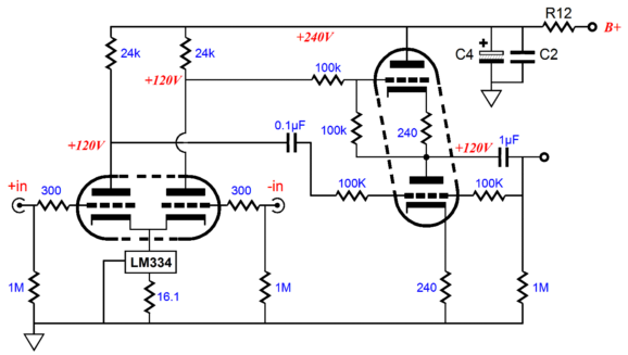
What’s your opinion of the use of a differential high gain JFET - tube cascode with (really) low ohmic IV resistors for IV conversion (like in one of your/Allen’s MC preamp designs) to start with? That stage could be followed by a balanced to unbalanced cathode follower like in Brosky’s Unbalancer (see picture).
I do understand that my question is a bit off topic because no transformers are needed then, but since you have explored high gain – low noise amplifiers in the past so much I wonder why you didn’t choose that as your point of departure.
I do understand however that many roads lead to Rome
.Peter
The best way is simply to measure it.
Example: Use a 1K resistor as reference. Play a sine wave, preferably at 0dBFS (full scale) and measure the output voltage. Then put 1K resistor across the output and measure the voltage it has dropped down to.
The rest is simple Ohm's Law:
Say you got 2V first and then 1V after with 1K load. The output impedance is the same as the 1K resistor. If it drops less than that, say 1.6V, then we can calculate:
2/1.6 = 1.25
1.25 * 1000 = 1250
1250 - 1000 = 250 Ohm
That's it.
I suspect with four DAC's in parallel you will get near 500 Ohm.
With 330R (2) to ground, it should be about 300 Ohm.
Both will drive 16K. In fact, it will drive 5K (less than 1dB insertion loss).
Cheers, Joe R.
Joe,
What’s your opinion of the use of a differential high gain JFET - tube cascode with (really) low ohmic IV resistors for IV conversion (like in one of your/Allen’s MC preamp designs) to start with? That stage could be followed by a balanced to unbalanced cathode follower like in Brosky’s Unbalancer (see picture)...
Hi Peter
While not the exact arrangement as you state, but yes, something very similar we have done on a regular basis using a device that is basically a "diamond transistor", very very low noise, huge bandwidth and as much gain as you need. It does have asymmetrical diff inputs, but with 1-3R that makes no difference.
If you have seen the Vacuum State Sony XA5400ES and Yamaha CD-S1000 and CD-S2000 that we have done, that's what they are doing.
Many ways to apply this one.
Cheers, Joe R.
The transformers I used are Tamura GA80071 as used in the Yamaha PM1000 mixing console. They are 600:1350 ohms which translates to a 1:1.5 step up ratio . . . I followed them with a diamond buffer to make sure there was sufficient drive. I loaded the secondary of the transformers with 15k ohms. I suspect that tweaking the loading of the primary and/or the secondary will have benefits . . .
After listening for the last week or so, I've gotten a feel the sound with this transformer + buffer output stage. It is nicely transparent but just a touch on the bright side. I suspect that the 15k load on the transformer secondary is a touch too high.
To understand what was going on, I put one of the transformers on the scope and tested it with square waves from 100hz to >100khz. The transformer response falls off rapidly between 100khz and 220khz but was quite flat up to a bit over 100khz. The leading edge of the square wave had a bit of ringing on it which could be damped completely by loading the secondary with 3600ohms. So I listened to the system with that load, but it was obvious that 3600ohms was over damping the system and squashing the dynamics. Going back to the scope, I saw that playing with higher loading didn't make an obvious difference in the square wave response. So it was back to listening tests to adjust the load to get something that sounded right in my system.
It turned out that a 10k load was just right. It still had all of the dynamics that were lost with a 3.6k load but it took the edge of the highs that I'd noted originally with a 15k load.
This mirrors my experience using transformer for MC phono cartridges. Playing with loading is critical to getting the sound dialed in. I'd recommend that anyone playing with transformers experiment a bit with the loading.
---Gary
To understand what was going on, I put one of the transformers on the scope and tested it with square waves from 100hz to >100khz.
Digital (through the dac) or analog?
Digital (through the dac) or analog?
Brian,
It was analog outside of the dac. I used a surplus Tek square wave generator and Fluke scopemeter. I added resistance in series with the square wave generator to mimic the output impedance of the Buffalo.
---Gary
buffalo III + mc-stepup...
hi! just ordered a buffalo III with ivy. at first i plan to listen to this combo to get something like a reference.
later:
dac output loaded with 2x 1R (the way mr. rasmussen suggests, should give around 10mv on the primary), S&B tx103 1:5, so we get 50mv. a mu-follower with 5842(~120v over each valve, 10ma, cathode resistor 150R)and a bartolucci "layered plate choke", 80H, between the 5842´s.
is something wrong with this plan or is it worth trying?
(have nearly all the parts lying around, including superreg from allen wright and choke input psu..)
thx, klaus
Last edited:
- Status
- This old topic is closed. If you want to reopen this topic, contact a moderator using the "Report Post" button.
- Home
- More Vendors...
- Twisted Pear
- Buffalo II & transformers