Hi,
Firstly, Like to thank everyone who posts on these forums, Ive just spent hours reading loads of posts and learnt tons! Cheers guys")
I have a pair of Quad II mono blocks, In ok condition and working fine, but they are all original specification. They have newish valves in.
I have read alot of sites where people have claimed to have given these amps a "new lease of life" with afew modifications..
What I cant seem to find is much info on what these mods are!. I have done all the usuall to them, Putting in a phono input, Bannana jack out, IEC mains plug etc, but nothing to the actual circuitry.
If any of you guys have any suggestions to whats possible I would be very greatfull for any input
Thanks again guys, Keep up the good work!
David
Firstly, Like to thank everyone who posts on these forums, Ive just spent hours reading loads of posts and learnt tons! Cheers guys
I have a pair of Quad II mono blocks, In ok condition and working fine, but they are all original specification. They have newish valves in.
I have read alot of sites where people have claimed to have given these amps a "new lease of life" with afew modifications..
What I cant seem to find is much info on what these mods are!. I have done all the usuall to them, Putting in a phono input, Bannana jack out, IEC mains plug etc, but nothing to the actual circuitry.
If any of you guys have any suggestions to whats possible I would be very greatfull for any input
Thanks again guys, Keep up the good work!
David
It's worthwhile reading the circuit analysis of the Quad II in Morgan Jones's book "Valve Amplifiers". He suggests replacing the cathode resistor and bypass cap. Other mods mentioned are increasing the B+ by going solid state on the power supply and rewiring the output stage to accommodate tubes other than the rare and expensive KT66.
Hello!
Not much to modify is it?
Change the old elcos to new ones or PP caps. The old PIOs for new ones or even Russian teflons. Get NOS original valves. Experiment with different resistors types.
There are discussions about the crap SS diodes send into a circuit, why add SS rectification to a Quad?
Experiment with the feedback resistor, increase it to 2,7k for example (warning: might get unstable).
Increase the cathode R to 220R.
cheers
New manufactured KT66 are dirt cheap and pretty good. Why would you want to change to another type when these are easily available?
If I were you, I would leave it mostly alone, maybe add a bit more capacitance to the power supply, and replace old capacitors and out-of-spec resistors. It is a classic design...
Get yourself some mullard or telefunken EF86s and some NOS rectifiers.
By the way, don't cut any metal, you will lower the resale value a lot. Reversible changes only!
shifty: I can agree with that, Saratov KT66 are good value for money, more slam and "raw" sound compared to NOS GECs,, but hey, the price difference...
The GZ32 can't take more than 47uF, though. Read somewhere that the second psu elco can be three times that size, but haven't dared to test it.
A non-inductive cathode R might be nice to try...as is less feedback
The GZ32 can't take more than 47uF, though. Read somewhere that the second psu elco can be three times that size, but haven't dared to test it.
A non-inductive cathode R might be nice to try...as is less feedback
Zombie said:The GZ32 can't take more than 47uF, though. Read somewhere that the second psu elco can be three times that size, but haven't dared to test it.
A non-inductive cathode R might be nice to try... as is less feedback
The second HT capacitor can be almost any value you like.
A non-inductive cathode resistor sounds like a very good idea. 10W thick film power resistors are available in this value and would make an ideal choice.
I assume everybody has seen this picture?
Attachments
Thanks guys for all your suggestions, Shall let you know what I end up doing!
Just another quick question regarding the GZ32 rectifier, One of my amps has the original GZ32, and the other has a replacement which is actually a GZ34.
I notice that GZ34's are much easier (and cheaper!) to get hold off, but is there any advantage/disadvantage with using them in the QuadII ?
Thanks again,
David
The GZ34 is an evolution of the GZ32. It can handle more current with less voltage drop on it, so it is a very good remplacement for the GZ32.
You will get more output power with it, without the need to use solid state diodes.
A thing you must be aware on the QuadII is at it become too hot with time, because the 2 KT66 are too close from each other. So, if you want to use it more as 2 or 3 hours at a time, you MUST install a fan in the proximity of each amp.
An externally hosted image should be here but it was not working when we last tested it.
I have used the Russian KT66 with good sucess in the QUAD II amps.... One main reason is the low plate voltage of the QUAD is kinder on these new production tubes....
I used the Groove Tubes KT66-HP and tried various strengths to measure agianst an original as well as figure which one sounds best in the QUAD II... It happens to get the #8 ratting from Groove Tubes for the KT66-HP for best Hi-Fi results....
Chris
I used the Groove Tubes KT66-HP and tried various strengths to measure agianst an original as well as figure which one sounds best in the QUAD II... It happens to get the #8 ratting from Groove Tubes for the KT66-HP for best Hi-Fi results....
Chris
David,
I have already posted a lot on your other Quad threads so beg patience from those who already read that, but your quiery here opens the field slightly.
Firstly you can replace the KT66 with a 6L6GC without any bother if you have trouble in getting the former. They should be easy to get and are so similar that SOVTEK uses the same innards for both! (If folks will measure they will find that the SOVTEK KT66 takes 0,9A heater current and not 1,27 as specified for KT66.) The 6L6GC also has a max. plate dissipation of 30W compared to 25W for KT66. One advantage of KT66s is that they do look very sofisticated!
But here I am obliged to sound a warning from dire experience - and which will be difficult to control when ordering. Some manufacturers are rather free with their designations. More serious than calling a 6L6 a KT66, is the fact that they take the old 6L6GB (23W) and glibly call it a 6L6GC. The visible difference is comparatively large cooling fins on G1 and the innards mounted directly on pins going to the outside pins for the GC, as contrasted to small or no cooling fins on G1 and the innards mounted on a glass tongue inside the tube with thin wires running to the outside pins as per old practice, for the GB. (The "direct" mounting method conducts more heat to the outside world - in this case the sockets.) Also avoid the Coke-bottle shape - the hot glass envelope is too close to the choke/power transformer and cooks it!
Other than that I would not change any values except power supply electrolytics. As said elsewhere I found some resistors to be off by up to 40% and I replaced with 0,5W 1% metal film types. I also mentioned moving the hot 180 ohm cathode resistor away from directly under the choke, and away from the cathode bypass capacitor, and increasing the value. You would have read this elsewhere. You could change the coupling capacitors on the KT66 sockets to polyester types, but I would advise just a check with a square wave and scope if you are able. The original "Hunts" capacitors contained in a metal tube have about 18 pF to earth. Without this your square wave might just show a little overshoot, which you could correct with outside caps. I have found some phase lead compensation by way of a 1,5 nF capacitor across the 470 ohm feedback resistor to be advantageous at the high frequency end in this regard.
I see no reason to decrease the feedback - it is after all part of the performance. The rather high input signal required should be no problem for modern ancillaries. I did on occasion replace the Jones input connector with an RCA, in which case some construction is required to cover the hole. (This is for separate pre-amplifiers.) I have also converted to the IEC power system.
Then there is every reason to change to a GZ34 rectifier - the heater current is the same. Power supply caps - I have changed to 100 + 100uF without a problem - one gets a decent dual from JJ. It is true about the max capacity for GZ32, but this also depends on the plate supply impedance. For the GZ34 any capacitance could be used provided there is at least 150 ohm plate-plate in series. The dc resistance of the Quad h. v. winding is already 150 ohm, the impedance at 50 Hz would be slightly higher. The old 16 + 16 uF is rather low. Lastly, be aware that the input filter capacitor needs to be able to handle a minimum ripple current. (That is why the original had a plain foil type at the input.) Do not just put the first small size available there.
I am not "drawing rank" (in this case experience and age!) here, but I have done a number of these over the decades, rewound power and output transformers, measured and listened, as others have. I would respectfully plead that you do not make unnecessary changes.
With that I think enough from me for the present.
Regards and success!
Stuart,
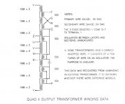
The Quad II output transformer is rather complicated, comprising 8 primary sections interleaved by 6 secondary sections. I will have to post a sketch for all to be clear, and Murphy has intervened. I cannot scan at the moment and will do that somewhere else and then post. Some patience please.
Regards.
Stuart,
I see that we have 2 Quad threads - hope you are reading here. I am now able to attach details about the Quad output transformer. I apologise for the long delay.
I must emphasize as I state on the attachment, that this data came from unwinding one transformer. I would not be aware of possible changes in different models.
Regards.
Attachments
405man and Tony....
I do wind QUAD II and MacIntosh output transformers from time to time....
I have analyzed the original design and in some cases made small changes to increase the bandwidth... Sometimes I have inserted screen taps...
If there is some info you need let me know...
Chris
I do wind QUAD II and MacIntosh output transformers from time to time....
I have analyzed the original design and in some cases made small changes to increase the bandwidth... Sometimes I have inserted screen taps...
If there is some info you need let me know...
Chris
Tony,
This was some time ago, and I unfortunately did not note the complete dimensions of the core, seeing as how I thought one would rewind on an existing core. I know of somebody that might have that, and will try to get it for those who want to try and have one wound from scratch.
I did note the following at the time:
Window: 22 mm
Tongue: 23.8 mm
Stack: 26.5 mm (i.e. 1 inch)
Generally speaking, if a Quad core is not available, any core of approximately the right size should give a satisfactory product. If it is significantly different, one could recalculate the wire gauges to fill the window.
The "gimmick" is where shown in the sketch. I have read some comments that it is a resistance of an ohm or so to "balance" things. That still does not make sense to me. For the 8 ohm connection the secondaries are balanced in the sense that leakage reactance would be balanced. I can also recollect reading that this gimmick was not present in some transformers. But all that was 2 decades ago. Perhaps someone else can comment.
Regards.
I am at work right now
When I get home in a few hours..I will look in my winding log book and provide the QUAD II transformer info....
From what I remember, they used standard Imperial core size at that time... I believe it was EI-112 ....but let me verify later on..
Chris
When I get home in a few hours..I will look in my winding log book and provide the QUAD II transformer info....
From what I remember, they used standard Imperial core size at that time... I believe it was EI-112 ....but let me verify later on..
Chris
Chris,
We seem to have posted simultaneously.
I must point out that the Quad transformer is already a distributed load (UL) design if one looks at the equivalent diagram. (The part of the primary between screen and B+ is simply put on the cathode side.) In this design the G2 "taps" are at 25% to place reasonable demands on the phase inverter. I am not saying though that you could not use extra screen taps, making the screen-B+ portion say 33% without having it all on the cathode side. But that would obviate the convenience of being able to use a lower screen voltage.
Since this I have always used this topology in tube amplifiers. In a recent 100W job I used a 33% screen-B+ section, all on the cathode side. That required a formidable 350Vpp maximum grid signal. I have since decided to stay with 20 - 25% in future!
Regards.
- Status
- This old topic is closed. If you want to reopen this topic, contact a moderator using the "Report Post" button.
- Home
- Amplifiers
- Tubes / Valves
- Quad II Mods/Tweeks