Johan....
I am fully aware of the QUAD II OPT and partly agree with you about the UL.... It is a bit different regarding the G2 tapping than just simply applying the "tap" to the cathode...
I do see a problem with the winding layout sheet... It shows connection from U to Z and W to X ..... The CATHODE winding should be DC isolated from the Plate winding...since these are only AC coupled...
Chris
I looked over some QUAD winding sheets I have for those interested...
If you were to look at the FULL primary of the QUAD output transformer you would see 3200 turns....This included the cathode winding.... You would get a Plate load of 3.786K into secondary of 16 ohms, 9 ohms and 4 ohms....
If one examines KT66 plate curves for the correct screen and plate voltages you will see this plate load is a perfect textbook fit...
The "distributed load" seperated for the cathode is 10% .....
So this means 2880 turns are in the plate winding and then 320 turns in the Cathode.... The Plate and Cathode windings are seperate and isolated..only AC coupled.....
I disagree with the # 36 gauge wire for the entire primary....that was only used in the cathode winding BUT paralleled by 3 to bring the Circular Mills/amp up to 75 which is acceptable....
The core was a EI-100 lamination...
I would ask Johan how the core was stacked on the transformer he has seen.... Since I have seen it two ways...I have seen the E-I lamination stacked 1:1 and another one was stacked at 2:2 groupings.....
Chris
One other note....
The open loop power output would be 25W calculated with 10% cathode feedback is applied... Then with global feedback loop the power output is reduced to 22W ......Which is about the MAX measured power output of most QUADS...
ALthough I did mention a 4 ohm tap in the previous thread...it is "un-official" since PIN Q on the output transformer is a feedback tap located at the 4 ohm .... The wire gauge would not support the current for a 4 ohm load at pin Q .....
Chris
ALERT - ERROR!
I am astonished at my own inaccuracies. Please everybody: In my previously attached diagram of the Quad output transformer there were errors as pointed out by Cerrem:
1. There are NO connections between points X-W and U-Z.
2. The sections VU and VW are not 160 turns x 3, but only 160 turns x 1 each, i.e. one layer. (The others are 160T x 3.)
I profusely apologise for this and am indebted to Cerrem for pointing this out. There is no excuse but perhaps an explanation would be considered: The print of my drawing came out light, especially some lines which were quite thin. The friend who scanned this for me drew in some of the lighter lines and accidentally also connected the above. This was then e-mailed to me and I did not look carefully at this again before pressing the button to attach.
The Quad thus uses 10% cathode feedback, indicating a 10% UL tap. I have just checked this on a Quad in my possession.
The data was written down 2 decades ago, and if you have an update on the #36 wire, Chris, please inform us. That is what I have noted at the time and can unfortunately not recall details now. Neither, unfortunately, can I recall the exact assembly of the core, but a local friend rewound such a transformer about a year ago, and I will mail him for details.
I agree with your calculations, Chris, only am not quite sure what you mean by "parallelled by 3" for each cathode winding, unless you took my erroneous indication of "160t x 3" as meaning 3 layers in parallel. That was not the case according to my notes, as said above. By the way, I have measured the primary d.c. resistances as follows for those interested:
XY = 119 ohm, ZY = 178 ohm, VW = 16,4 ohm, VU = 16,8 ohm
I am also not with you when you say that "It is a bit different regarding the G2 tapping than just simply applying the tap to the cathode". As I see it in the equivalent a.c. diagram, one "breaks" the primary winding at the tap, calling the [anode-G2] part Y-Z (per the previous sketch) and the [G2-B+] part V-U; V and Y being the same point for a.c., i.e. the G2 tap of the basic UL configuration. How am I misunderstanding you?
Once again apology for the errors and my profound thanks to Chris.
Regards.
Calm down, Johan - to err is human. I'm wondering about your 10% cathode feedback ratio. I measured the voltage ratio between the windings and obtained 9.375:1 rather than 9:1. I'm reasonably confident about my (single) measurement, so I'm wondering where your turns figures came from. I'm not saying I'm right, but it would be nice if we could all agree.
EC8010...
Are you using two seperate AC meters both using the same RMS processing??? Are both meters calibrated??
If using one AC meter for both measurements, loading errors will exist...
WHich winding are you exciting for this measurement???? Cathode excitation current is significant to cause such error..
I have seen the windings in a number of QUAD OPT's and they come up to 9:1 for the distributed load...
The Cathode winding is 3 paralleled sections for each side of cathode...each of 3 sections is uniformly sectionalized between plate windings to reduce leakage and increase coupling with plate winding which is extremely critical for Hi-Fi.....
I have redesigned the QUAD OPT on EI-112 with lower turns and better band-width....
Johan...
Do you remember how the EI laminations were stacked on the OPT you took down????
Chris
Thanks EC8010.
Only when "to err is stupid" rather seems to sum the situation up, perhaps the boot should be applied to a certain area of the anatomy.
I went and switched the Quad on for the second time tonight. Measured under signal conditions I got ratios of 8,45 for both tubes at 300 Hz; 9,16 and 8.95 respectively at 2 KHz; and 9,09 and 8,89 respectively at 7 KHz. (This was not the same amplifier I had repaired then.) I do not have an amplitude (cursor) readout scope and has to judge by eye. I got the number of windings back then by unwinding and counting. Could a mistake have crept in? - possible, but the sections were all equal, so I cannot explain the discrepancy. The most I can do is enquire locally whether others also have data. I would be surprised if I were the only one to have ever had to rewind a Quad output transformer.
Cerrem seems to have data; hopefully also figures for number of windings? The discrepancy will not make much of a difference in practice, but as you say, it would be nice to have agreement.
Regards.
Cerrem
We seem to be mailing simultaneously. But you now have me worried, I can definitely not recall the 3 cathode sections you mention. Could mine have been a very early model?
Also, having thought about it, the very low cathode impedance bypassing the cathode winding could be what you meant by the earlier mentioned difference. (That would not exist were such a winding from G2 to B+.) I have also made my own designs for higher output and used 20 - 25% cathode windings without experiencing difficulty, but that was for class AB and I had to sectionalise the primaries quite some more for proper performance. (I used fewer secondaries.) In one instance the cathode windings were bifilar to parts of the (anode) primary, but I did not find that to be noticably better than sections.
Do you have a windings count?
Johan...
I did provide windings count in one of my previous threads, this was based on data I have from 8 years ago....
3200 total primary windings....2880 for the Plates, 320 for the cathodes.... Lamination was EI-100 ......
I modified the design slightly from the original in that I wind this OPT with better coupling between cathodes and plates...I felt the original OPT had inadequate coupling between plates and cathode windings.... I use 6 cathode layers that are uniformly interleaved within the plate windings, thus lower leakage inductance between all the primary sections... ALso use better di-electric materials with lower dielectric constant....
The problem with varnish impreganated paper is that the di-electric constant is far from constant, it has a slope based on applied voltage gradient..for example I measure the full frequency bandwidth of the QUAD from 5W to 22W in increments and the plots show the high frequency pole droping with applied increasing power output, since the leakage is truly constant as a function of winding geometry, thus the increased winding capacitance...
The newer materials I use show a more stable freqeuncy response over wide range of power....
The original OPT had a peak inductance of 135H .....The 3200 turns @ 20W @ 20Hz given this core size, would normaly push the flux density a bit higher than conservative Hi-Fi design...but by stacking the core in very large groups...your effective gap increases enough to buy you another 1000 Guass of usable headroom, so all is well...the inductance is still way up there and no need for worry... At 135H the low frequency -3dB pole is roughly 6Hz.... i usually wind up with over 200H
Chris
Tony said:johan, chris,
just to make sure i understand, are the plate windings and cathode windings in phase or not?
by large groups stacking, you mean in groups of say 8 lams or more? instead of the 1 to 1 or 2 by 2 method?
thanks
The Plate and Cathode windings are in PHASE...they must be for the feedback to work...Since the AC signal at the plate is out of phase with the signal at the cathode.... SO the windings are in phase but the signals from the tube are out of phase..
In a McIntosh OPT, you have equal turns in plate and cathode windings and the windings are also in PHASE...this gives 100% feedback, thus UNITY VOLTAGE GAIN coupling... Think of it same as a Cathodyne phase splitter but with transformer loading..
WHen you stack E-I lams by 1:1 ...there is a tiny gap, it can be calculated with accuracy..as you increase the groupings such as 5:5 or 10:10 or all the way up to like a Single Ended OPT with all E's grouped and all I's grouped...the effective gap increases and linearizes the BH loop for a bit more clean head room at expense of lower "effective" permeablity...don't over do it, then you loose too much inductance..but if you already have way more inductance than you need...this is the way to go.... I make my QUAD OPT's with 10:10 groupings of laminations and they sound cleaner and less colorized by the affects of core distortion...
Chris
405man said:Johan and Chris, have you unwound an ESL57 transformer, I would be interested in winding a Quad II output transformer to drive the ESL57s directly, any thoughts
Stuart
I have given that some thought in the past...but never implemented a plan to do so.... I would love to give it a try..Need more info on the ESL57 High-Voltage transformer...
Chris
Chris,
Your mail #29 (I am not going to quote) is most clear and you have obviously done more on the output transformers than I did - I only repaired, I think, 2 long ago, although as said I have designed a few for my own stuff. Also apology for overlooking the turns given. I am usually posting after midnight here, perhaps not a good idea:xeye
I then also misunderstood you (I think I missed a post) regarding the many cathode sections; that was your own design and not the original I cannot add much more, except to perhaps give figures I measurted on the OPTs of 2 Quads in my possession (serial numbers 53125 and 49000 - would you believe it).
Inductance of full primary at 5V 50Hz: 39 Hy and 34 Hy
Leakage reactance at 1 KHz, full primary to secondary shorted: 11 mH and 11,2 mH
Anode primary (XZ) to shorted catode winding (UW shorted): 113mH and 106mH
Just as an exercise I calculated the anode/cathode winding leakage with some guesswork as to dimensions (but no back-engineering!) and got 118 mH, so everything seems to fit.
Yes, the leakage anode/cathode winding is rather high; - 3 dB response at 9 KHz calculated (I did not measure). But that excludes the further coupling caused by the interleaved secondary which could lift the frequency slightly.
Tony,
Likewise I have not yet ventured that far but there is a guy here in the RSA that has done that. I will try to trace him and post his experience when I am able to.
Regards
Johan
Your mail #29 (I am not going to quote) is most clear and you have obviously done more on the output transformers than I did - I only repaired, I think, 2 long ago, although as said I have designed a few for my own stuff. Also apology for overlooking the turns given. I am usually posting after midnight here, perhaps not a good idea:xeye
I then also misunderstood you (I think I missed a post) regarding the many cathode sections; that was your own design and not the original
I cannot add much more, except to perhaps give figures I measurted on the OPTs of 2 Quads in my possession (serial numbers 53125 and 49000 - would you believe it).Inductance of full primary at 5V 50Hz: 39 Hy and 34 Hy
Leakage reactance at 1 KHz, full primary to secondary shorted: 11 mH and 11,2 mH
Anode primary (XZ) to shorted catode winding (UW shorted): 113mH and 106mH
Just as an exercise I calculated the anode/cathode winding leakage with some guesswork as to dimensions (but no back-engineering!) and got 118 mH, so everything seems to fit.
Yes, the leakage anode/cathode winding is rather high; - 3 dB response at 9 KHz calculated (I did not measure). But that excludes the further coupling caused by the interleaved secondary which could lift the frequency slightly.
Tony,
Likewise I have not yet ventured that far but there is a guy here in the RSA that has done that. I will try to trace him and post his experience when I am able to.
Regards
Johan
Hello all,
I recently become the owner of Quad II. I was reading most of the threads on this topic but still had some questions to ask. I did not want to open a new one so I decided this is the best to what I want to ask.
My quads are with all original tubes in great condition (checked on the tester, all 4 GEC tubes are around 60mA and Mullard GZ32 and EF86 are all in good shape).
But:
As someone noted after two hours of listening my amps (specially the choke) are very hot. I can touch the choke but I would say it is like 50°C. Also I feel that the power transformer is just hot (much less, I would say 45°C) but from the tubes near by, since this side is hotter then the other one.
Since there is no power switch I hope the amps were designed to work with these temperatures (hopefully even after 50 years) even for a prolongued amount of time. Do you have the same experinece? Is someone listening to them for more then 2 hours? Will change to GZ32 and 6l6 types without coke bottle shape change the temperature much?
Thank you in advance,
Pred
PS
Please do not recommend me to change the amp, it is for me match from haeven with my Focals
Hi Pred,
No need to change the amplifiers (to what I wonder) - but perhaps something in the amplifiers. Yes, they do get hot, but in Switzerland? OK, perhaps ignorance; we foreigners always think of Switzerland as cold only.
If you say 'original tubes', I take it you mean classic shape KT66s. These days one also gets Coke bottle shaped Russian ones. STAY AWAY! With them the glass does come too near the output transformer and heat it up. What's more, the insides of those are exactly Russian 6L6GBs - only here they cost twice as much! On output valves, change to 6L6GCs (when necessary) is advantageous. The heater current is less but the maximum plate dissipation more than for KT66. The characteristics are within 10%. (And for heavens sake, do not use with EL34s!)
A point (pardon if you have read this in the thread previously; I did not check): I presume you have 230V 50Hz mains. The Quad power transformer was a little over-designed voltage-wise (probably OK with all ancilliaries connected). Keep your mains setting (the screw on the side) at 240V. Then replacing the ugly old GZ32 with GZ34 is advantageous. It operates cooler, and h.t. rises to about 370V. This is still within the limits for valves, and will give a quite clean 17 - 18W.
Pred, inside you can change one item to make a difference. The hot KT66 cathode resistor sits right under the choke. Firstly, I change that to a 10W resistor; the rated 3W resistor works at maximum. Then bend that away to the output transformer side of the mounting terminals on the choke (to the other side, it will fry the cathode bypass electrolytic). If the amps have worked for some time, that capacitor would already have been compromised - on refurbishing many Quad IIs I have never found one that was still in order.
Regarding a power switch, that came with the Quad pre-amp for which the IIs were designed (the power amp power chord came from the pre-amp).
These amps should be able to work for long times when well ventilated. If there are still heat problems after the above, I fear that someone competent (if not yourself) must check matters out. There are also other item changes one can make after 50 years, but not to make this post too long.
I hope this helps; you can also PM me.
Quad IIs run hot. As Johan says, replace that cathode resistor and capacitor immediately. Make sure they have good ventilation. I assume you have cleaned all the dust off...
Hello,
thank you both on the answers. Well I am versed in electronics so I will remeasure the amp over the weekend (if I find time, 2 small children
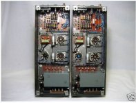
) and report to you. I want to change this awful rifa with some mkp that I have around.I think it is the GEC valves and GZ32 (I like the looks of this tube!). The guy that I bought the amp from did some mods, well updates of the components. You can see on the picture that coupling caps are Jensen PIOs and that the cathode resistor is a 5W at least, I would say more like 7W. Is it far away enough? The capacitors are cerafines, I do not know what is the value. For the electrolytic he told me that he reformed them with slow rise of voltage, by 50V every hour. Resistors, except two are changed but this should not be a reason. I will see but I feel not comfortable with the heat. The amps are on the top of my hi fi shelf so they have plenty of space around and above them. The amp runs from 230V mains and I plugged the thinggy into 230-250 tap.
I do not feel I need more power, this is Switzerland, neighbours get disturbed easy
What is your opinion on JJ GZ34, is it reliable there are some guys on ebay selling them cheap and I would like to try. If I see the heat dropping then I would maybe try a pair of 6L6GC just to see the effect and if all is good to go and find some nos tubes, and sell GEC for a fortune (anybody interested )Here is the photo of the amp and any comment would be helpfull
Pred
PS
There is a joke about Swiss. " Last year the summer in Switzerland was on tuesday".
Attachments
Hi Pred,
Do you have a circuit diagram? Sorry not to have a reference right now, but it is readily available. (Mine came from www.geocities, but I believe they do not exist any more.)
If so, then there are several further matters. Firstly about that hot resistor (R12). In your photos it still sits right under the choke - that will heat it up as previously said. You can either use longer leads and move it right over to the output transformer side out from underneath the choke, Or perhaps more practical, move it over to where the capacitor is at present (C5) or even closer to the rectifier socket. Get it away from right under the choke. You can instead mount the capacitor C5 straight over the tie-poins on the choke terminal board - you would have realised that those terminals are just convenient tie points; no connection to the choke inside.
Then second important point. It is frequently found that the two Hunts coupling capacitors C2 and C3 are leaking. This is measured easiest by checking that the KT66 bais voltage is not significantly higher than 26V. It is difficult to measure the grid dc accurately even with a 10meg input digital multimeter. Easiest is to again measure the voltage over R12 with C2 and C3 connected, and then without them connected - the bias reading should be the same as you will guess. Obviously, if there is a difference, C2 and C3 will need replacement. (And here - though I may step on toes - please dispense with spending a whole lot on boutique capacitors. Polyester/polypropilene is quite satisfactory.)
For an initial test on heat generated: Take out all the tubes and leave the amps running for some two hours. Then replace all but the GZ32, and test again. Over both runs they should remain cool - luke-warm transformers. You might now attend to C2, C3. It would have been more direct to do the previous voltage measurements over R12, but you can also disconnect C2,C3 from the KT66 grids (pins 5). Running the amps that way; if they are cooler, would also indicate over-current in the KT66s as a result of leaking C2, C3s. (If you measue KT66 grid voltages, do note that there is about +0,6V on G1s - the grid resistors R7, R8, R9 are not going to common but shares some potential from the EF86 cathodes network.)
Then, should you replace C2, C3, it will probably be with ones without a metal sheath clamped to common. Those metal sheathes place about 18pF capacitiy from each G1 to common. Leaving that out is not serious, but if you have access to a 'scope and square wave generator, you will notice a slight overshoot on the leading edges. A rather better way to correct for the mentioned 18pF is not to replace them, but to do a phase advance correction over R11 - one places a 1nF - 1,2nF capacitor over R11. The results should be visible on the 'scope.
While this is already long: I mentioned that I often left the capacitors C4-C6 alone. They were still good, and it can be a schlepp to mount other types neatly. If you are of an industrious nature, you can replace the caps inside the tin and retain the original appearence. C4-C6 is a round double-C inside that square tin. With a hot soldering iron it is not much of a problem to unsolder/pry open the bottom of the tin - it comes off. The cap inside will be secured by some pitch at the bottom; not too much of a job to get it out and get the tin clean - I fear the lettering will suffer. Then one gets good enough modern smaller Cs to enable one to mount them back inside the tin. A sophisticated double C I used (expensive) was the 50µF + 50µF 500V made by JJ. With some patience and not too much heat (you say you solder for a profession!) the original appearance can be restored and the 'tin' resprayed 'machinery grey'.
As an engineer I appreciate the advantage of silicon rectifiers. But they also provide instantaneous h.t., and cathode stripping of the tubes is a practical danger - apart from having to deal with a peak initial h.t. surge.
To plead moderation: If you consult the internet, folks come along with wonderous 'tweaks', almost changing the design. Grid stoppers, fancy wire, fancy capacitors, twin RCs for the KT66 cathodes, goodnes knows whatever. I have restored my modest few, and I can assure you that none of such tweaks make a difference. One keeps the amp as close as possible to the original, which is mercifully possible in this case. If one wants a more fancy amplifier, one goes and buys something else. Peter Walker was not stupid, and used the design he did for a reason.
Sorry for a rather lengthy missive; these from my experience. (And I did find relocating R12 important!)
- Status
- This old topic is closed. If you want to reopen this topic, contact a moderator using the "Report Post" button.
- Home
- Amplifiers
- Tubes / Valves
- Quad II Mods/Tweeks