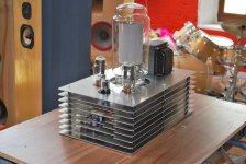
Am I stupid to do that ? only WE300B can deliver 8 watts, actually RCA808 can up to 12 watts, but really red hot. now 5 watt look more comfort for them, only reason for this is 808 in positive bias driving, sound completely different, my personal favor. big power supply in left, just for a 5 watts amp
Tony KY Ma
nooooo...
I'm driving a Telefunken RS607 with a 6EM7.....
1Kw in, 25W SE out.
per Channel
RS607 or Tubezilla
Attachments
nooooo...
I'm driving a Telefunken RS607 with a 6EM7.....
1Kw in, 25W SE out.
per Channel
RS607 or Tubezilla
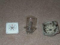
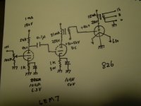
I did a 6EM7 drive 826 in 250V amp at 12 years ago, can have 8 watts out, what bias for your RS607 ? + or - ? positive bias always has more efficiency
6EM7 very easy to use and easy to get but different driver come in different sound, so I switched to 56+46, sound better.
Tony KY Ma
Attachments
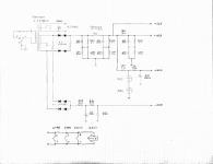
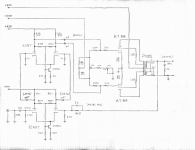
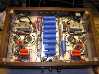
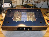
I recently finished this stereo KT88 ultralinear amp- It began as a far simpler flight of fancy and one thing led to another...
It's not quite ALL tubes... the input and splitter are cascaded differential amps using an NPN to balance the stage(s). Very good balance, convenient way to apply feedback, and good output voltage swing from the splitter. A novel approach that seems to work well.
Specs turned out well:
It's not quite ALL tubes... the input and splitter are cascaded differential amps using an NPN to balance the stage(s). Very good balance, convenient way to apply feedback, and good output voltage swing from the splitter. A novel approach that seems to work well.
Specs turned out well:
Code:
                        Both Ch. driven      One Ch. driven

Clipping level	+26.8  dBV               +27.0 dBV
			21.9V RMS               22.4V RMS
			60 W ( 8 Ohms)       62.7 W (8 Ohms)

Input sensitivity:	1 VRMS at the input will drive the amp into clipping.


Open loop gain:	+47.5 dB
Closed loop gain:	+27.8 dB
So there's almost exactly 20dB feedback.


Noise: -81 dBV (100 kHz signal BW) so 20 kHz S/N well in excess of 110 dB.
One of these days I *have* to build a 20 kHz noise filter...

The power supply reactor and the 0A2 regulators do wonders here.


THD at clipping:	0.25%			0.25%
THD at -10 DB		0.067%			0.067%
(6.9 VRMS - 6 W)

N.B. My signal generator has about 0.067% THD so I can't really measure the distortion at normal listening levels.
So the amp is better than my generator...  One of these days, an HP 339 would be nice to have...


THD at Clipping Vs. frequency:
	100 Hz:		0.48%
	1 kHz:		0.25%
	10 kHz		0.38%


Frequency Response:	-1 dB at 20 Hz and 20kHz
			-3 dB at 10 Hz and 40 kHz


Damping Factor:		24.3 (output Z is 0.33 ohms)
Attachments
I recently finished this stereo KT88 ultralinear amp- It began as a far simpler flight of fancy and one thing led to another...
It's not quite ALL tubes... the input and splitter are cascaded differential amps using an NPN to balance the stage(s). Very good balance, convenient way to apply feedback, and good output voltage swing from the splitter. A novel approach that seems to work well.
Specs turned out well:
Code:Both Ch. driven One Ch. driven Clipping level +26.8 dBV +27.0 dBV 21.9V RMS 22.4V RMS 60 W ( 8 Ohms) 62.7 W (8 Ohms) Input sensitivity: 1 VRMS at the input will drive the amp into clipping. Open loop gain: +47.5 dB Closed loop gain: +27.8 dB So there's almost exactly 20dB feedback. Noise: -81 dBV (100 kHz signal BW) so 20 kHz S/N well in excess of 110 dB. One of these days I *have* to build a 20 kHz noise filter... The power supply reactor and the 0A2 regulators do wonders here. THD at clipping: 0.25% 0.25% THD at -10 DB 0.067% 0.067% (6.9 VRMS - 6 W) N.B. My signal generator has about 0.067% THD so I can't really measure the distortion at normal listening levels. So the amp is better than my generator... One of these days, an HP 339 would be nice to have... THD at Clipping Vs. frequency: 100 Hz: 0.48% 1 kHz: 0.25% 10 kHz 0.38% Frequency Response: -1 dB at 20 Hz and 20kHz -3 dB at 10 Hz and 40 kHz Damping Factor: 24.3 (output Z is 0.33 ohms)
Outstanding crafstmanship! Never seen the addition of 2N3904's like that. They are cheap and plentiful around my place.
Thanks for the kind words, Bob!
I spent the vast majority of the circuit development time on the splitter, which evolved into the differential stage you see. I couldn't get enough voltage swing with a concertina so spent quite a bit of time on the paraphase, mostly the floating paraphase, a whole different animal than a paraphase. But the two outputs are considerably different- one output has the distortion of a single stage- the other output has essentially no distortion since the waveform is inverted and therefore "pre-distorted" as an input to the second stage of the paraphase. So the KT88s don't see the same waveshape. A long-tailed pair was the next thing I looked at, but to do this right, one really needs to feed the two cathodes with a constant-current sink, usually to a negative voltage. By the time I was done with the negative supply and the constant current sink, it made for a pretty complicated arrangement. The arrangement I arrived at uses the two high-value resistors from the plates to the NPN base to achieve balance, and the current through the collector is set by (Vb - Vbe) / Re. Easy. No negative supply needed, and the balance is independent of tube parameters. The voltages appearing at the plates are very(!) nearly identical except for phase, with just one input driven. Or to put it another way, Common-mode rejection of the stage is quite good (abt 50-60 dB).
I could have taken the outputs from the 12AX7 and run them through two independent sections of the 6SN7, but it's so easy to make the 6SN7 into a diff amp, might as well take advantage of differential gain in the voltage amp, too.
The 2N3904 isn't at all critical- a reasonably high beta works best of course, and there's only a few volts Vce and Ie is only a few mA.
So far I like this circuit- a nice thing to add to the repertoire.
It was my first real woodworking project; next is to learn some "real" joinery, though the "screw-and-glue" reinforcements for the mitre joints work OK, too.
Thanks for the reply.
Last edited:
An externally hosted image should be here but it was not working when we last tested it.
6X5GT in the power supply of my Mapletree Line 2A.
T-Rex Push/Pull
Not really fancy, but it gets the job done:")
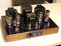
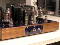
Williamson based design with two KT88s per channel. Delayed start, independent power supplies, black anodized chassis.
Not really fancy, but it gets the job done:
An externally hosted image should be here but it was not working when we last tested it.
Williamson based design with two KT88s per channel. Delayed start, independent power supplies, black anodized chassis.
Not really fancy, but it gets the job done:
An externally hosted image should be here but it was not working when we last tested it.
Williamson based design with two KT88s per channel. Delayed start, independent power supplies, black anodized chassis.
very nice chassis.
Loren42,
Nice amp. Is it class A or AB? Fixed or Cathode biased? Triode, UL or Tetrode wired? How much power output?
Class AB, fixed bias, push-pull ultralinear. I have not measured the power, but the plate dissipation is set to 28 Watts each KT88 with a B+ of 505 VDC, so it should deliver between 50 and 60 WPC.
Drivers are 6SN7GTs with a concertina phase splitter driving the KT88s.
The other nice thing about this amp is that it has totally independent power supplies. Essentially, it is two mono-blocks on the same chassis. Weight is 42 pounds (19 kg).
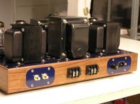
I mounted the transformers onto a 1/4" plate T6061 aluminum. There is another 1/4" plate that acts as an internal divider inside the chassis that separates the rear half (power supply section) from the front half (tube section) of the chassis. The divider acts as a truss to support the forward lip of the transformer plate and a signal isolation shield from the audio side of the chassis. Chassis is 17" wide and 10" deep with another 1/4" brushed aluminum black anodized faceplate on the front.
Inside there are 4 PCBs; one each for the left and right power supplies, a turn-on delay board to delay B+ for 60 seconds, and a audio driver board for the four 6SN7GTs. The output tubes are point to point wired.
Class AB, fixed bias, push-pull ultralinear. I have not measured the power, but the plate dissipation is set to 28 Watts each KT88 with a B+ of 505 VDC, so it should deliver between 50 and 60 WPC.
Drivers are 6SN7GTs with a concertina phase splitter driving the KT88s.
Very cool. I am going to build something similar for my next project. What's the impedance of your output transformers?
Very cool. I am going to build something similar for my next project. What's the impedance of your output transformers?
Mine are 4.2K, but the impedance depends on the type of tube you are using and how many.
That is, for a single pair of KT88s like I have, 4.2K is the right number. If I use two pairs or four KT88s per channel, the impedance should be 1/2 that amount.
This is very nice looking amp. What type of paint did you use. I'm at chassis finishing point of a "Retro-Mod" project on a Maggie 8606 console amp. Because the chassis is rather small there is a lot of heat build up. I would prefer to use an air brush rather than brush or use a spray can.
Thanks
Thanks
This is very nice looking amp. What type of paint did you use. I'm at chassis finishing point of a "Retro-Mod" project on a Maggie 8606 console amp. Because the chassis is rather small there is a lot of heat build up. I would prefer to use an air brush rather than brush or use a spray can.
Thanks
Greetings! The paint is actually black type II anodizing. Painting aluminum is a big pain as paint will ultimately flake and peel unless you use a commercial primer like zinc-chromate.
I use anodizing for all my commercial/military products and it is more resilient than paint in most cases.
We also powder coat some of our aluminum products that can not be anodized, but in this case I wanted black anodizing and the last batch of goods we sent in to the anodizer I simply dropped in the parts of the amp so they could be done for essentially free.
My 833 amps and system
Amps: 2X125W 833 single ended
DAC: 8XTDA1541A Parallel I2s connected non oversampling dac
Transport: Marantz CD80 I2s connected, non oversampling modified
Loudspeakers: Tannoy Saturn S10
Amps: 2X125W 833 single ended
DAC: 8XTDA1541A Parallel I2s connected non oversampling dac
Transport: Marantz CD80 I2s connected, non oversampling modified
Loudspeakers: Tannoy Saturn S10
An externally hosted image should be here but it was not working when we last tested it.
An externally hosted image should be here but it was not working when we last tested it.
An externally hosted image should be here but it was not working when we last tested it.
An externally hosted image should be here but it was not working when we last tested it.
Last edited:
Amps: 2X125W 833 single ended
DAC: 8XTDA1541A Parallel I2s connected non oversampling dac
Transport: Marantz CD80 I2s connected, non oversampling modified
Loudspeakers: Tannoy Saturn S10
Those are amazing!
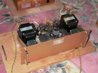
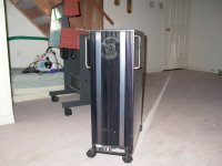
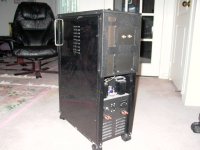
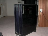
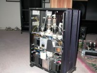
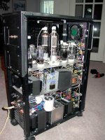
Xerox copy machine's power supply case recycle for power amp use
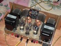
I picked up this case for free, took off most of inside, left the main switch and the cooling fan only, this huge monster is stereo single end class A 50 watt with two power supplies. 3B25 is the rectifier, #26 300B 810 is the amp's tube, because too many irons I had put it on wheels , this amp is good in winter, for the hot summer it should take a rest
Tony KY Ma
Attachments
.jpg)
I picked up this case for free, took off most of inside, left the main switch and the cooling fan only, this huge monster is stereo single end class A 50 watt with two power supplies. 3B25 is the rectifier, #26 300B 810 is the amp's tube, because too many irons I had put it on wheels , this amp is good in winter, for the hot summer it should take a rest
Tony KY Ma
Nice job Tony,
I like it! Great use for a re-purposed electrical cabinet. Looks like it was just about big enough for all the parts. I have three 810's in parallel in a tabletop tesla coil. They throw a lot of heat. You should put clear plexy sides on the top tier to show the glow.
Are you cathode direct coupled from your drivers or using an I.T.? What output iron did you use on the 810? Plate voltage? This tube is like a mighty 805 with considerably more balls.
- Home
- Amplifiers
- Tubes / Valves
- Photo Gallery