I tried another pair of speakers that are roughly 88 - 90db/watt efficient, and still around 4 - 6 ohm and still the same - to put it in perspective, about as loud & as clear as my SI T-Amp (10 - 15 watt Tripath). The Tube amp does sound a bit more full and robust compared to the T-Amp - and shouldn't surprise anyone.
I still beleive something is not quite right, but am quickly thinking it's a bit more work than I want to indulge in at the moment...
As far as the question regarding what part of the tubes were glowing, I will take a picture tonight and post...
Thanks for the help again...
I still beleive something is not quite right, but am quickly thinking it's a bit more work than I want to indulge in at the moment...
As far as the question regarding what part of the tubes were glowing, I will take a picture tonight and post...
Thanks for the help again...
Hi John,
Yeah, on post #65. Those plates are way too hot! Measure the voltages on the outputs for chuckles but you need the see what's between cathode and grid on the 6SL7's. The grid needs to be more negative than the cathode. Also check the plate voltage for the 6SL7's.
You should find this amp to be very dynamic. It will sound much louder than it's 20W rating would suggest.
BTW, I have both sand & hollow state amps. I love them both and they each to things a bit differently. For power I'm driving some PSB Stratus Golds with a 35W / CH Eico. No problem (and they are 4 ohm too).
-Chris
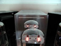
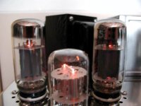
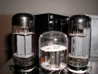
The pictures make the tubes look a lot more brighter than they really are...I had the flash off and dropped the camera sensitivity so the glow looks brighter than it really is.
I can say that the rectifier tubes feel quite hot - I can hold my hand over the tube and feel the radiant heat. The power tubes feel quite cool, and the driver somewhere in between.
Now for the dumb question...how best to get those tube voltages. I do not beleive I can drop a DMM probe into the sockets with tube removed to get the voltages (I need the tubes in to get the running voltage correct?)
Is there an easy way to get those voltages so I don't have myself in any real danger?
I have been trying to avoid getting those voltages....
Hi John,
The outputs shoud be very warm. The rectifiers sound like they are normal.
To measure voltages you would normally get right in there with a meter set to it's highest scale. Use heatshrink on the probe tip to expose only the tip. Clip the negative lead right to the chassis - there it stays. There used to be a product series that would plug in between the tube and it's socket with exposed terminals to make measurements.
Raise the chassis securely and stick your left hand in your pocket. If you are unsure or uncomfortable with this, have someone help you who is experienced. Make sure no one disturbs you. PAy attention to what you are doing at all times.
-Chris
 What Chris said. Be VERY careful, this is DEADLY dangerous stuff you're playing with. It only takes a moment of inattention to cause a permanent lack of attention- or any other brain activity.
You might be able to pull the tubes of interest up slightly to expose some of the pins. Get in there with your probe tip. Be very careful not to burn yourself on the tubes.
Many injuries are also caused by jerking your arm back when burned or shocked. You can get a really nasty gash that way. Someone else should be present within earshot while you are working in case you become injured.
I don't believe SY can over emphasize the need to be careful. Just because I've shocked the heck out of myself over the years does not mean you should. And this stuff can kill you ... you can't see it or smell it until you feel it.
Oh, rubber soled shoes on a non-conductive mat and bench helps.
-Chris
Did it...
OK, well, I got those voltages, ALL of the votages....
Anyway, with no input, and speakers connected to the output, I got these voltages:
Rectifier #1 5R4GYB; P2(481V); P4(3V); P6(-3V); P8(481V)
#2 5R4GYB; P2(483V); P4(2V); P6(-3V); P8(483V)
Driver #1 6SL7GT; P1(0V); P2(187V); P3(2V); P4(8V); P5(243V); P6(49V); P7(2V); P8(2V)
#2 6SL7GT; P1(0V); P2(187V); P3(2V); P4(9V); P5(235V); P6(53V); P7(0V); P8(2V)
Power #1 6L6GC P1(0V); P2(3V); P3(363V); P4(367V); P5(0V); P7(3V); P8(29V)
#2 6L6GC P1(0V); P2(3V); P3(364V); P4(366V); P5(0V); P7(3V); P8(29V)
#3 6L6GC P1(0V); P2(3V); P3(361V); P4(365V); P5(01V); P7(3V); P8(28V)
#4 6L6GC P1(0V); P2(3V); P3(362V); P4(365V); P5(0V); P7(3V); P8(28V)
So in summary,
Power Tube 6L6GC (min/max)
Plate Voltage (361V/364V)
Cathode Voltage (28V/29V)
Driver Tube 6SL7GT (min/max)
Plate Unit #2 (187V/187V)
Plate Unit #1 (235V/243V)
Grid Unit #2 (0V/0V)
Grid Unit #1 (8V/9V)
Cathode Unit #2 (2V/2V)
Cathode Unit #1 (49V/53V)
So whaddya all think? Dump her?
Power Tube 6L6GC (min/max)
Plate Voltage (361V/364V)
Cathode Voltage (28V/29V)
Driver Tube 6SL7GT (min/max)
Plate Unit #2 (187V/187V)
Plate Unit #1 (235V/243V)
Grid Unit #2 (0V/0V)
Grid Unit #1 (8V/9V)
Cathode Unit #2 (2V/2V)
Cathode Unit #1 (49V/53V)
So whaddya all think? Dump her?
I am guessing that the filament voltage readings are in error. Either they are DC readings, or they are readings taken with respect to ground and the filament windings may not be grounded ( or both). If you look carefully at the photos of the tubes you can see the cathode in the 6SL7, and in the right 6L6. They are glowing red, just about the right amount of red. I doubt that the filament voltage is the real problem.
There are some obvious clues in the voltage readings.
#1: 5R4, the rectifier readings Pins 4 and 6 are the plates, they are recorded as small DC voltages, when they are large AC voltages, this is why I believe that the filament readings are incorrect.
#2: 5R4, Pin 8 is the cathode, 481 volts in one tube, 483 in the other. Two power transformers. This implies seperate power supplies for each channel. Both have similar readings. The voltage would not be this high if the transformers were set for 240V. Chances are the power supplies are OK.
#3: 481 volts at the rectifier cathodes, only 365 at the plates and screens of the 6L6's. 116 volts are getting lost somewhere. I am guessing it is in those big resistors, or an undersized choke, or both. At any rate if 116 volts are dropped at idle current, what does the plate voltage do at full volume. This is likely the real problem. Connect the meter back up to pin 4 of one of the 6L6 tubes, hook the amplifier up, stand back and turn it on, you should again read close to 365 volts. apply a signal and turn up the volume and read the voltage. Ideally the voltage should not drop, in a real amp it will drop some. If it drops a lot (25 volts or more), this is your problem. Somebody may have modified this amp to use cheap 6L6's. Good ones can take 450 volts. Fender used to feed them 500 volts or more. The early Chinese ones would blow up on 400 volts.
#4: The 6SL7 readings don't make sense. Grid Unit #1 (8V/9V). Cathode Unit #1 (49V/53V). If these readings are correct this tube section is in deep cutoff and therefore not doing anything. This might be a problem, but I doubt it. Something like this would cause no sound, or really distorted sound.
One more time...
One more time, with AC values
Rectifier #1 5R4GYB; P2(1082V); P4(428V); P6(429V); P8(1083V)
#2 5R4GYB; P2(1079V); P4(428V); P6(429V); P8(1077V)
Driver #1 6SL7GT; P1(0V); P2(379V); P3(4V); P4(9V); P5(496V); P6(106V); P7(2V); P8(3V)
#2 6SL7GT; P1(0V); P2(378V); P3(4V); P4(10V); P5(483V); P6(115V); P7(2V); P8(2V)
Power #1 6L6GC P1(0V); P2(3V); P3(804V); P4(812V); P5(0V); P7(3V); P8(63V)
#2 6L6GC P1(0V); P2(3V); P3(805V); P4(813V); P5(0V); P7(3V); P8(63V)
#3 6L6GC P1(0V); P2(2V); P3(807V); P4(815V); P5(0V); P7(2V); P8(63V)
#4 6L6GC P1(0V); P2(2V); P3(806V); P4(814V); P5(0V); P7(2V); P8(63V)
Quite a bit of difference, but the heaters are still under 6.3V...
Hi john65b,
Something is really off here! These readings do not seem to make any sense at all. I'm thinking the heaters are wired to one half the winding instead of across it. The filter caps appear to be open and the HT AC supply is reading way high.
The center tap should be grounded. Are you measuring the heaters across the pins or from chassis ground to each pin?
-Chris
Are you measuring the heaters across the pins or from chassis ground to each pin?
I'll bet the latter.
- Status
- This old topic is closed. If you want to reopen this topic, contact a moderator using the "Report Post" button.
- Home
- Amplifiers
- Tubes / Valves
- DIY Tube Amp Questions