")
Huh...
Yep, I always thought it sounded very good and tight...
Is that crazy that the colored rings show 27Kohm and it measures only 2Kohms? And that both identical reisistors (per channel) check out at 2kOhm? and labeled 27kOhm?.
I find that bizzare.
The original owner literally gave this amp away to my friend for some reason, maybe this is why.
How often you you all check resistor values against their respective value ratings when troubleshooting problems?
What the heck....
This just keeps getting deeper and more crazy...I took the 27Kohm resistor that was reading 2Kohm out and read it with a voltmeter )out of the amp circuit) and it correctly read 27kOhm. I was so sure I found the problem.
After putting the 27kOhm reistor back in the amp, and scratching my head, I realized the negative speaker outs were grounded to the chassis, taking the entire feedback loop and the positive speaker output to ground with it. Now I have been reading that the outputs should not be grounded to the chassis, so I disconnected the negative speaker outputs to ground and retested all feedback resistors and it read correctly at 27kohm/2.15kOhm.
I put a dummy load across the speaker outputs and put in a test tone cd and read the speaker output with a voltmeter with preamp at full crank - with negative speaker output (and rest of feedback loop) grounded it was 12V, and ungrounded it was 18V, so I gained a bit of gain disconnecting the ground.
I am about ready to just leave it be, as it sounds a bit louder now without the negative speaker outputs grounded. I am thinking about experimenting a bit by replacing the 27Kohm resistor with a 40kOhm resistor with the 2.15kOhm resistor to increase gain, but may just leave it be.
Still sounds good - very clean and no hum, and a little bit louder now.
john65b,
With those values in the feedback network, your signal should be about 13.3 times larger than your input level at 1KHz, as long as you are not clipping.
Can someone else check me on this?
Does this agree with what you are getting (output level in volts divided by input level in volts).
-Chris
With those values in the feedback network, your signal should be about 13.3 times larger than your input level at 1KHz, as long as you are not clipping.
Can someone else check me on this?
Does this agree with what you are getting (output level in volts divided by input level in volts).
-Chris
Let's hope...as I have not yet heard the new "fix"
Is it correct to say that the negative speaker outputs on Tube amps should never be grounded?
I am building a few LM3886 chip amps (sounds pretty damn awesome BTW) and most of these chipamp designs call for the Negative speaker outputs be grounded, along with the negative line inputs...
Just design variances between technologies?
Hi John,
Grounding on any amplifier must be done carefully. With tube amps, another winding may already be grounded. Grounding the common would then short out a section of the secondary. Not what you want.
I do not recommend grounding any amplifier output to the chassis. The speaker return normally goes to the start ground in the power supply.
-Chris
Well, just tested the sound and gain is back!! Loud and clear!
I still might fart with the Feedback Resistors to get a bit more than 13.3V/V...
Anyone have a rule of thumb as far as how much is sonically ideal? 13.3V/V (27kOhm/2.15kOhm) seems low... 23 should be good (48kOhm/2.15kOhm), right??
Thanks for the help all! All is finally well with my sick amp!!!
On to the next challenge!.
So let's shoot for 30db gain...
Gain (db) = 20 log(Rf/Ri), wich gives me 65K/2.15K resistors...also gives me a 31V/V gain. Quite a bit more than what I currently have...wonder how much bandwidth I will give up...hopefully it's bandwidth in the inaudible range...
I will test it out tomorrow when my boy is asleep (hope not to wake him)
Hi John,
You may find that somewhere the amp sounds very alive and the bass is reasonable. Too much feedback and the bass is better, but the life gets sucked out. Not enough feedback and everything gets loose and uncontrolled.
Since you have a low powered amp you may not want too much gain there. It's a balancing act. The actual gain figure is unimportant.
Be aware that the amp may become unstable at some point. The high frequency compensation may need to be adjusted at different gains.
-Chris
Driver gain, more output
Hi John,
Without a schematic it's hard to follow exactly what you have there. The good is that you seem to have almost a dual mono amp with a beefy power supply. The bad is that there are very few driver designs that use just one dual triode.
I've not followed the thread completely but I think PRR is right that you've got one gain stage followed by a phase splitter and in the typical configuration you do not have enough gain to have both high sensitivity and enough feedback.
I think that you've disabled the feedback by lifting the output ground, it needs to be grounded but then you'll be back to low gain.
The Fender Twin Reverb power amp uses just one dual triode but in a diff pair setup, and it needs about 3 to 4 V in for full output.
Early VTL amps used a simple design that requires 3 triodes, so you'd have to add another tube.
I see that the supply voltage was lowered through resistors, if you want more power, the thing to do is run the full 485 V to the output stage, you might want to switch to EL34s or 6550s and then get a driver stage that provides enough gain. Fender ran 6L6GCs at 525V but it's beyond the max ratings and you have to use only the best tubes.
Well this is nearly rebuilding the whole thing, did you give it back?
Pete B.
Interesting high gain 2 triode driver
This is the first I've seen of this interesting 2 triode configuration that uses positive feedback or bootstrapping to dramatically raise the gain of the first stage:
http://www.angelfire.com/electronic/funwithtubes/Rst_Harman-Kardon_A-300.html
Note the author's measurements of an increase in voltage gain from 55 to 515 for the first stage:
"A very interesting point is the phase splitter and the tube just before it. The cathode of the half of a 12AX7 goes to the same voltage divider as the cathode of half of the 12AU7. If you connect the cathodes of two triodes together and couple the plate of the first to the grid of the second you have a schmit trigger. The cathode is tapped way down so the result is positive feedback but not with enough loop gain to sustain oscillation. I breadboarded this much of the circuit and made some measurements. The gain measured out as a whopping 515. At the necessary voltage output to drive the 6V6s the distortion was 0.90% from the cathode of the 12AU7 and 0.92% from the plate.
I decided to see how much of an increase in gain and distortion this positive feedback was producing. First I measured the DC voltage at the cathode of the 12AX7. Then I disconnected the cathode from the junction of the 300 ohm and 20 k ohm resistors and inserted a cathode resistor and bypass capacitor. I used an adjustable resistor and set it for the same DC voltage as measured above. Then I measured the gain and distortion again. The gain was 55.3 and the distortion was 0.38% from the cathode and 0.36% from the plate. Interesting. The gain was increased by 19.4 dB while the distortion was increased by 7.8 dB. "
Interesting and simple design. One thing to note is that the increased gain will raise the input capacitance due to the Miller Effect, something to keep in mind and of course the design can be adjusted for less boost in gain. Looks a bit like the ST-70 but with a bootstrapped triode rather than a pentode first stage.
Pete B.
Interesting thread and intersting amp. My guess is that the 6sl7 is either a long tail pair phase inverter with one grid grounded to make it a "self-split" type arrangement, or it is a conventional gain stage followed by a cathodyne phase inverter. Either way you only get gain of a single 6sl7 stage, which I think is about mu = 60.
I would recommend lifting the feedbackas you have done, and perhaps bypassing any tone controls there might be.
My choice for more gain witout adding tubes is rewiring the halves of the 6sl7 as 2 gain stages, and then wiring the output pair of 6l6s in the self-split configuration above. The 6sl7 has a high-ish plate resistance which is not very good for driving an output stage like this, but they can still sound very good.
jsn
PB2 - yes, I have the amp permanently now- but currently considering a trade for a ZAPpulse or UCD Amp with a few mates from the other side of DIY Camp..
Now that the "Gain Bug" has been solved via the ground connections and feedback resistors (at least to my liking), I feel that maybe an operating Tube Amp may not be best left around the house with a curious two year old...
Anyway, learned quite a bit in the five months I tinkered with this amp. Too bad that it was a bit underwelming on my main system Magnepans...many on this site had told me months ago that they would likely not be a very good match...
Anyway, if the trade doesn't pan out, I will still keep her around, as she really is an impressive and nice looking conversation peice, and still sounds fantastic on my other DIY speakers.
John
Wow, almost 3 years later and I am now jut getting back to this amp. Since playing around with this tube amp, I have gone on to make a few Tripaths, UCD, a Krell clone, and a few preamps (12B4, AN M7, and an Aikido that's not quite finished)
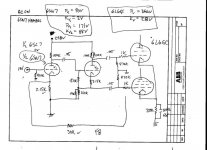
Anyway, I have "found" a couple pairs of RCA and GE 6SN7 driver tubes that came with this tube amp - I had thought that the drivers were 6SL7 because that's what was in the amp. I really don't know what really "belongs" in this amp. I have taken some critical voltages (Plate, cathode of both the 6SN7 and one of the the 6L6 output tubes.
6L6GC
Plate 366V
Cathode 28V
6SN7
Plate 1 90V
Cathode 1 2V
Plate 2 171V
Cathode 2 88V
Anyway, I have just drafted the input section (with the FB) leaving a bit of the 6L6 and PS circuit out.
The amp sounds very nice with either the 6SL7 or the 6SN7. I expected to hear quite a difference due to the gain differences of the two.
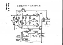
Anyway, can anyone comment on the input section? Which is correct driver and what can I do to improve the design (without adding another tube)? Anyone familiar with this topology? It reminds me of the Magnavox Mag-1515 (with different input and output tubes) here:
MAG-1515
If you begin at the start of this thread you will see that I have had quite a few comments and advice on the initial gain problem of this amp with the 6SL7. Just isn't very loud, but once I put a nice pre that had a little gain in front, all was fine.
A few pics posted here:
DIY Tube Amp
There really was not a lot of advice from the beginning of this thread on a 6SL7 driving a Pair of 6L6, but I have seen the AN P2SE amp is....
I apologize for all the crazy questions, but I am just a bit excited to be finally getting back to this amp!!
Anyway, I have "found" a couple pairs of RCA and GE 6SN7 driver tubes that came with this tube amp - I had thought that the drivers were 6SL7 because that's what was in the amp. I really don't know what really "belongs" in this amp. I have taken some critical voltages (Plate, cathode of both the 6SN7 and one of the the 6L6 output tubes.
6L6GC
Plate 366V
Cathode 28V
6SN7
Plate 1 90V
Cathode 1 2V
Plate 2 171V
Cathode 2 88V
Anyway, I have just drafted the input section (with the FB) leaving a bit of the 6L6 and PS circuit out.
The amp sounds very nice with either the 6SL7 or the 6SN7. I expected to hear quite a difference due to the gain differences of the two.
Anyway, can anyone comment on the input section? Which is correct driver and what can I do to improve the design (without adding another tube)? Anyone familiar with this topology? It reminds me of the Magnavox Mag-1515 (with different input and output tubes) here:
MAG-1515
If you begin at the start of this thread you will see that I have had quite a few comments and advice on the initial gain problem of this amp with the 6SL7. Just isn't very loud, but once I put a nice pre that had a little gain in front, all was fine.
A few pics posted here:
DIY Tube Amp
There really was not a lot of advice from the beginning of this thread on a 6SL7 driving a Pair of 6L6, but I have seen the AN P2SE amp is....
I apologize for all the crazy questions, but I am just a bit excited to be finally getting back to this amp!!
Attachments
Hi John,
I'm glad I had subscribed to this thread. I got the notification of a new post and I'm excited to see what you do withthis amp.
Here are my two cents:
There are 4 things about this amp that make me want to gut it and rebuild the circuit from scratch using the existing parst. 1) global negative feedback, 2) cahodyne phase inverter, 3) grounding to the chassis, 4) general rat's nest wiring. Ok the wiring isn't so bad, and the feedback could be simply clipped, but still.
If you are willing to gut it, I am working on an idea for the circuit for your consideration and to maybe spark some ideas.
Thanks for the posts!
jsn
- Status
- This old topic is closed. If you want to reopen this topic, contact a moderator using the "Report Post" button.
- Home
- Amplifiers
- Tubes / Valves
- DIY Tube Amp Questions