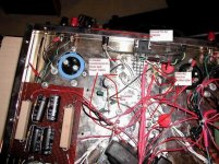
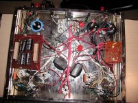
I have the DMM clamped and grounded to chassis. I am not going pin to pin on the heaters (ie, one hand in my pocket). The pic shows what the power transformers (two of them) look like. The top right white wire are the 120V from the outlet, and just below that as shown in the pic, is the Rectifier tap that show 1080VAC.
All measurements were made with the ground clamped...
All measurements were made with the ground clamped...
Attachments
Re: One more time...
Hi there........the high anode volts on the driver 6SL7 (pin2) (pin 5)....... looks like a cascode driver config ..... ..... however the heater on driver 2 at 4V is way underrun....and in time will ruin the cathode with high B+........swapping for another known good tube would rule out heater/cathode problems....but perhaps there's some duff component discoloured under/chassis. Inspect.
However it looks you measured the heater centre tap which should be raised to avoid heater to cathode problems.I assume you taking all voltage measurements i.e With reference to ground/chassis. And it looks the heater centre tap is grounded.right/wrong ??
Note the max heater/cathode rating for 6SL7 shouldn't be higher than 90V. For non NOS, I would design not even half this.
A circuit scribble would be nice............note bogey heater values on most 6.3 heatered tubes are nom 6.3V +/-10% i.e operating tolerance from 5.7 to 6.9V. Under running heaters doesn't help tube life nor proper performance unless specified.
richj
john65b said:One more time, with AC values
Driver #1 6SL7GT; P1(0V); P2(379V); P3(4V); P4(9V); P5(496V); P6(106V); P7(2V); P8(3V)
#2 6SL7GT; P1(0V); P2(378V); P3(4V); P4(10V); P5(483V); P6(115V); P7(2V); P8(2V)
Quite a bit of difference, but the heaters are still under 6.3V...
Hi there........the high anode volts on the driver 6SL7 (pin2) (pin 5)....... looks like a cascode driver config ..... ..... however the heater on driver 2 at 4V is way underrun....and in time will ruin the cathode with high B+........swapping for another known good tube would rule out heater/cathode problems....but perhaps there's some duff component discoloured under/chassis. Inspect.
However it looks you measured the heater centre tap which should be raised to avoid heater to cathode problems.I assume you taking all voltage measurements i.e With reference to ground/chassis. And it looks the heater centre tap is grounded.right/wrong ??
Note the max heater/cathode rating for 6SL7 shouldn't be higher than 90V. For non NOS, I would design not even half this.
A circuit scribble would be nice............note bogey heater values on most 6.3 heatered tubes are nom 6.3V +/-10% i.e operating tolerance from 5.7 to 6.9V. Under running heaters doesn't help tube life nor proper performance unless specified.
richj
Whoops, the 1080VAC are not the red wires in th pic, they are the black wires in the lower right of the Primary Side of the Power Transformer. They feed the Filament of the recifiers (pin 2 & 8). The red wires off the power transformer Taps feed the Plates of the rectifier, and they are 428V...
That is a strange looking power transformer, I'd believe military. You have very high AC readings were you should have DC only. Looking at your earlier DC readings, you seem to be losing an awful amout of voltage from the supply to the plates of the outputs.
With the power off and caps discharged, measure the DC resistance of the supply to each plate of the 6L6's. At this point you should take a bit of time and look at the schematic, or draw it out. Actually, draw it out even if you have the schematic. It's possibly wired wrong.
-Chris
With the power off and caps discharged, measure the DC resistance of the supply to each plate of the 6L6's. At this point you should take a bit of time and look at the schematic, or draw it out. Actually, draw it out even if you have the schematic. It's possibly wired wrong.
-Chris
Like PRR said earlier, the power transformers look to be Mil Spec and may be higher voltage than we want.
The DC resistance from Pin 2 on rectifier (Filament) to plate on output tube is 970 ohms - all four power tube supply to plate DC resistance are are within 20 ohms of 970 ohms.
The two monster resistors on the left hand side are 820 Ohm-25 Watts each- they connect to the other side of the filiment (pin 8) of both rectifiers...this is where the big voltage drop should be, correct? Someone pointed this out to me earlier in this thread.
As far as the heater voltages on power and driver tubes, if I check the voltage across the heater pins, I get 6.4V (I thought we needed 6.4V from chassis ground to each pin - like I said, I'm new)
Maybe replace the power transformers with "correct" lower voltage ones and ditch the 820 ohm resistors?
Are the power tubes and driver tubes overdriven by the power transformers in this amp? Are the DC Voltages or AC Voltages "Correct" and to be compared to the the maximums on the Power and Driver tube datatsheets?
Like I have been saying, the amp sounds good, but I just wanted it a bit louder. I wonder if i really want this amp since I don't know, if at these high voltages and possible overdriven tubes, I could have a potential catstrophic failure in my possesion.
Any of you live in the Salt Lake City Area?? Or know of anyone who works on Tube amps?
Tube Specialist
John,
There is a guy in Salt Lake City. His name is Robert J. Silk, and he lives up on the benches of Sugarhouse. He went through an Eico ST-40 that I picked up a few years ago. His number is (801) 583-6616
You need to call to make an appointment, as it is not his regular line of work. Good luck!
Lyndon
P.S. Check out his retro sound system in the living room. Pretty amazing tube system.
Okay... so this is the wrong thread to say this...
I'm, not a proponent of either tubes or transistors... I listen with my EARS, NOT my BRAINS.
That said, there is only ONE SS amp I'd truly consider for my system... well, okay TWO... the FORTE' Model 4 and Model 7. There is only ONE brand of tube amp I would consider for my system... VTL.
I haven't heard a great many tube amps, but one VTL I DID hear COMPLETELY KICKED ***... above EVERYTHING else I've heard... MONEY NO OBJECT!!!!! Sadly... even BETTER than my Forte Model 4's and 7's... and THESE are TOUGH TO BEAT!!
BUTT... I don't want to MESS with replacing tubes... I don't want to constantly listen for TUBE AGING. SO... I'm keeping my Forte Model 4's and 7's.
Sincerely,
A Worthless, Lazy Audiophile
The news
Well, got the news from the local tube expert on my "sick" amp. There really nothing wrong, just the circuitry is very gain limited...or in retardo terms even I can understand, gain is approx 4V/V (normal gain is around 20V/V??). This proves my initial perception that the amp wasn't loud. He also checked the wpc and confirmed 25 - 30wpc.
Other than that he said it was fine. Distortion levels were decent and everything else checks out. He mentioned the one thing he would do (if he owned the amp) is rip out the driver circuitry and put in a whole new setup to get better gain and sound - as the 6SL7 was not a very good driver, period.
Also, in the meantime, he recommended swapping the two rectifier tubes from 5R4 to 5AR4 since we have spare capacity in the caps and tubes/circuitry to get another 30V and thus 7 wpc. But this additional 7wpc wasn't going to make a big difference in the overall gain.
When I have a bit of time, I will post a schematic.
Thanks all

Looks to be a Williamson Type
Looks to be a Williamson type circuit...which I already have a few schematics - Thanks anyway
I am really wondering if there is such a circuit with just one 6SL7 driver (sans 6SN7) with a 5AR4 rectifier and a pair of 6L6GC that anyone my know of...
Don't know if one exists, as the one I have isn't really makin' me happy...
I think I finally found the problem on my good sounding, but very low gain (hence not so loud) Amp.
The feedback resistor is supposed to be 27Kohm, but when I measure it, it's only 2Kohm. the other resistor to ground is 2kOhm too, so 1+Rf/Ri gives me gain of 2V/V, while if it were a 27kOhm, it would be gain of 14.5V/V.
Aha!!
I will replace the resistor tomorow and see if the gain increases...
The feedback resistor is supposed to be 27Kohm, but when I measure it, it's only 2Kohm. the other resistor to ground is 2kOhm too, so 1+Rf/Ri gives me gain of 2V/V, while if it were a 27kOhm, it would be gain of 14.5V/V.
Aha!!
I will replace the resistor tomorow and see if the gain increases...
- Status
- This old topic is closed. If you want to reopen this topic, contact a moderator using the "Report Post" button.
- Home
- Amplifiers
- Tubes / Valves
- DIY Tube Amp Questions