Hello!
I have an amp where I have just change the input stage from 12AT7 to ECC88 to get lower gain (which I did).
Problem is that I do not find the amp dynamic anymore.
Before I convert the amp back to 12AT7 input again I have been adviced to try to run some more current throw both the input (ECC88) and the driver/phase splitter (5687).
Problem is that I am not sure on how to do it.
Can anyone give me some clues where to start and which operating points (and voltages) I should get ideally if I would like to drive the input- and driver tubes hard?
Attachments
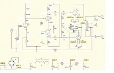
The current through the ECC88 looks OK, around 4-5 ma. It could go higher, but no need. The 5687 is running a bit light. If it were my amp, I'd go for an active current source in the 5687 cathode, try to raise the B+ on it, equalize the plate resistors, and up the current to more like 3-4 ma per section.
Understand that the ECC88 will give you significantly less gain than a 12AT7/ECC81, so that lack of dynamics may simply be a function of where you've set the system levels.
Understand that the ECC88 will give you significantly less gain than a 12AT7/ECC81, so that lack of dynamics may simply be a function of where you've set the system levels.
Looking at the 5687 data sheet, I have second thoughts- get that current up to more like 10mA per section. That means you'll either have to have a higher B+ for it (much higher!) or drop the plate resistor values or both. With a 450V B+, you could drop the plate resistors to something like 30K. And a current source for the cathodes will be almost mandatory; lowering the cathode resistor value will increase the phase splitter unbalance.
Hi,
You could also try to lose the global feedback loop too.
It's eating most of the gain and I really doubt it's needed for a PP 2A3.
The unbypassed cathode resistor of the ECC88 should provide some local degenerative feedback, linearizing that stage.
Phase splitter as per SY's suggestion, get those plate resistors equal at the very least.....
You could have done the lot with a single ECC88, one half for input voltage gain, the other half as a cathodyne splitter, for instance.
Input sensitivity would probably sink considerably compared to the ECC81 set up but as you are not complaining about that, I assume you're using a preamp of the "gain to burn" type anyway.
Or else:
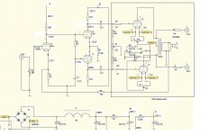
Courtesy of Dutch Triode Dick. I tried it, nice and simple....After all making things complicated is easy..........
Cheers,")
You could also try to lose the global feedback loop too.
It's eating most of the gain and I really doubt it's needed for a PP 2A3.
The unbypassed cathode resistor of the ECC88 should provide some local degenerative feedback, linearizing that stage.
Phase splitter as per SY's suggestion, get those plate resistors equal at the very least.....
You could have done the lot with a single ECC88, one half for input voltage gain, the other half as a cathodyne splitter, for instance.
Input sensitivity would probably sink considerably compared to the ECC81 set up but as you are not complaining about that, I assume you're using a preamp of the "gain to burn" type anyway.
Or else:
Courtesy of Dutch Triode Dick. I tried it, nice and simple....After all making things complicated is easy..........
Cheers,
Attachments
Frank, is that schematic correct? The tap for the other side of the phase splitter looks funny.
The problem I would anticipate with ECC88 voltage amp to a split-load is the ability of the first section to linearly swing enough voltage to drive the 2A3. Or do I worry too much?
The problem I would anticipate with ECC88 voltage amp to a split-load is the ability of the first section to linearly swing enough voltage to drive the 2A3. Or do I worry too much?
Hi,
The bottom part I suppose you mean?
According to the fellow who designed it, it is correct...
It had me scratching my head too but then the entire phase splitting looks off with only one of the cathodes bypassed too.
Dixit the same chap, he has that trick from a Philips engineering book.
I once modded a PP 2A3 of mine that way and it seemed to work just fine.
No, you're quite right.
It was just a cheap and cheerful suggestion, one I think would still work better than what Taffi has now IMO.
If it were me facing that amp I'd leave the ECC81 and just optimize the splitter, perhaps fiddle with the feedback loop or throw it out altogether.
I don't see why the input sensitivity/gain of the amp would be a problem if it's working fine otherwise.
Cheers,
The tap for the other side of the phase splitter looks funny.
The bottom part I suppose you mean?
According to the fellow who designed it, it is correct...
It had me scratching my head too but then the entire phase splitting looks off with only one of the cathodes bypassed too.
Dixit the same chap, he has that trick from a Philips engineering book.
I once modded a PP 2A3 of mine that way and it seemed to work just fine.
Or do I worry too much?
No, you're quite right.
It was just a cheap and cheerful suggestion, one I think would still work better than what Taffi has now IMO.
If it were me facing that amp I'd leave the ECC81 and just optimize the splitter, perhaps fiddle with the feedback loop or throw it out altogether.
I don't see why the input sensitivity/gain of the amp would be a problem if it's working fine otherwise.
Cheers,
SY said:Well, I can see how it works, I just had problems seeing how it could work well. I need to play around and see if indeed the source impedances are balanced because at first glance, it looks like they're not.
Yes, it looks like if that was done deliberatly, and I can't understand why
What about having a common unbypassed cathode resistor ?
Mmmmh, may be worst because it introduces some positive feedback on the first triode
Yves.
Well, first of all:
Thanks to all that are willing to help me on this
Let me first tell you a little bit more about the amp.
The amp by itself are not a completly DIY amp, but a kit that I have bought and built.
Because of that it is not so easy to make bigger changes such as getting a much higher B+ and so on.
For now I have to stick with small changes such as changing resistors.
The reason for changing from 12AT7 to ECC88 was to get less gain since I use speakers with very high sensivety( Duo's).
So I was adviced to use ECC88 from the man who sells the amp and he also told me that he thought it sounded better too.
Well IMO it don't (even with a good Siemens ECC88).
So I just want to try the ECC88 with higher current before I eventually have to rebuilt it again with 12AT7.
Regarding the current source I am not enough into that to understand it at once, but I am sure that if I seek this forum I will find the info needed.
(IF it is very easy though maybe someone could just tell me).
I do not either understand why the amp is built with different values plate-resistors on the 5687's.
Has it something to do with the 1M restistor the signal passes throw before it goes to grid on the one halt of the tube?
If I understood it correctly your advice is to use the same values plate resistors (which I has done), but I still wonder why it originally are made with different values.
And the same goes for the negative feedback.
Why is it there in the first place if I just can take it away?
And should I just take away the 20K feedback resistor or should I instead try another value (higher or lower?)?
In the schematics below I have done my best to get the currents up just by changing resistors, but can not see how I can get the current throw the 5687's as high as 10mA.
It all depends on how low cathode resistor on the 5687's I can use.
More advice needed!
Now I am down to 10K, but even then it's less then 7mA throw each section of the 5687's.
There is one way that I can get this current higher and that is by reducing the plate resistor on the ECC88 from 10K to about 5K.
This will make the grid- and cathode voltages up by 20V and then also the current throw the 5687's (both halfs together) up to 15,mA), but at the same time it will reduce the voltages over the ECC88 plate resistor from 70V to 50V which I don't know is wise.
Or is it just no way around using the current source (which I first have to find out what is)
Is it safe to try the amp as it is right now or have overdone it and need to higher some resistors again?
Attachments
I see that there has become some faults in the schematic:
- Over the upper plateresistor on the 5687 it says 201V.
It should have been 281V
- Over this it is a letter that looks like an F.
Original it was a B.
- The ECC88 resistor are 10K.
- The anode voltage on the ECC88 are 130V and the cathode voltage are 3,3V.
- The R6 10K resistor that looks like it are not connected to anything are in fact the 5687 cathode resistor.
Hopefully everything else is clear.
Dropping the ECC88 plate resistor will limit the swing, drop the gain, and increase the distortion. I'm not sure why you'd want to do that. With limited B+, you ought to be going in the other direction, to an active current source or at least a 45-50K resistor. Running the tube at 8-10 mA ought to keep the effective plate resistance reasonable and hence keep the bandwidth acceptable.
If you want to be tricky and fool the 5687 into thinking it's got a real he-man supply, add a negative rail and run the tube between those two rails instead of between B+ and gound. And you still want to use an active current source in the cathode lead. Take a look at the schematic for the Crystal Palace amp in Morgan Jones's book to see one good implementation of these methods.
If you want to be tricky and fool the 5687 into thinking it's got a real he-man supply, add a negative rail and run the tube between those two rails instead of between B+ and gound. And you still want to use an active current source in the cathode lead. Take a look at the schematic for the Crystal Palace amp in Morgan Jones's book to see one good implementation of these methods.
Konnichiwa,
I am quite familiar with the Amp you write about.
Before I completely reconfigured the amp for a very different circuit I used a 6072A in the first stage and a frequency compensated attenuator between stages (plus no NFB).
This attenuator used the resistor feeding the second grid as the shunt element (adjusted in Value) and a series resistor between the anode of the input valve and the grid of the first valve in the phasesplitter as series element. A small capacitor shunting the series resistor was used to frequency compensate the circuit under inclusion of the output transformer.
You do need serious measurement gear to get this running though.
I do not think the ECC88 in the first stage is a good choice at all, try a 6CG7 (will need adjustment of Cathode R).
Also, from experience, DO NOT increase the 5687 current, it is fine where it is. Increasing the current invariably makes the sound more compressed and edgy, based on my experience. Of course, you may want your Amp to sound like that.
If you are prepared to radically alter the circuit of the Amp but want something simple, something akin to the circuit fdegrove showed would be my choice, probably using 6072A or 6N1P and with one or two small changes, such as a common cathode R and no bypass capaitor for the pair.
Sayonara
First of all I am using the amp right now.
It plays pretty good especially if we talk about hifi terms.
Nothing hard and no glare and it sounds ok in most parameters.
But I still remember the amp as sounding more dynamic with 12AT7 (especially when used with an active preamp).
I have tried it both with and without a preamp.
And the sound as it is right now could also be too much "hifi" so I am still seeking out different solutions.
As I guess most of you have understood I am absolutely not an expert in DIY and therefore first of all looking for solutions that I can do myself and which are not too difficult.
The amp are also built with a pcb and therefore it is not too easy to change to different kind of tubes.
The 6CG7 is an miniature tube as far as I can see and then need another socket than the ECC88.
If not it had been easy (and interesting) to try this.
BUT is it possible to find some kind of socket that I just can put into the ECC88 socket and then the 6CG7 will fit I???
Regarding the current in the 5687 I see that there a quite different opinions and I guess that the best is that I try myself what I like best.
If I understood T correctly one idea could be changing the posision of the volume pot (and I absolutely like the idea since my feeling is that most amps with a passive vol pot on the input do not sound as dynamic as other ones with a more active solution).
Or have I misunderstood it?
Konnichiwa,
Yes. But gain will go way up.
6CG7 & 6DJ8 have identical pinout, but the 6CG7 is basically a 6SN7. In many circuits 6CG7 & 6DJ8 are interchangable, in some the cathode resistor needs changing.
Go for it.
No, this is NOT what I did. I in effect added a 10db attenuator between the first and second stage (12AT7/6DJ8 & 5687).
This simply lowers overall gain without significant drawbacks. But it does require a lot of experience and serious measurement gear to get it right.
Sayonara
Taffi said:Could I just take away the negative feedback resistor (20K) anyway which tubes I use as input (ECC88, 12AT7, 6CG7, 6072A)?
Yes. But gain will go way up.
Taffi said:The 6CG7 is an miniature tube as far as I can see and then need another socket than the ECC88.
6CG7 & 6DJ8 have identical pinout, but the 6CG7 is basically a 6SN7. In many circuits 6CG7 & 6DJ8 are interchangable, in some the cathode resistor needs changing.
Taffi said:Regarding the current in the 5687 I see that there a quite different opinions and I guess that the best is that I try myself what I like best.
Go for it.
Taffi said:If I understood T correctly one idea could be changing the posision of the volume pot
No, this is NOT what I did. I in effect added a 10db attenuator between the first and second stage (12AT7/6DJ8 & 5687).
This simply lowers overall gain without significant drawbacks. But it does require a lot of experience and serious measurement gear to get it right.
Sayonara
Re: Re: ECC88/5687/2A3 amp voltages
Have some qouestions thow:
- To make it even easier could I use 5687's instead of 6922/6072A/6N1P?
- Is there any difference in the total gain of the amp using these different tubes (I think I will have no problem living with less than 10db.
- Do the grid resistors have to be 1K or can I use 100 ohm Vietrohm as I do today?
- Is the 290V B+ as I have today enough?
- Could I use the 50K PEC pot that I have today or do it have to be 100K (IF I should use it without an active preamp).
- What values of plate- and cathode-resistors and what anode- and cathode-voltages should I have if:
a) using 5687
b) using 6922
c) using 6072A
d) using 6N1P
- And what about the three resistors used to feed the second grid?
Maybe they also need to be different values for the tube choosed?
- Could I use the same heater- and balancing-connections as I use today for the 2A3's?
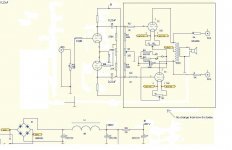
- Could I use a schematic something like this one attached?
I looked into this schematic and even if I do not understood how it looks really interesting (read: easyKuei Yang Wang said:Konnichiwa,
If you are prepared to radically alter the circuit of the Amp but want something simple, something akin to the circuit fdegrove showed would be my choice, probably using 6072A or 6N1P and with one or two small changes, such as a common cathode R and no bypass capaitor for the pair.
Sayonara
Have some qouestions thow:
- To make it even easier could I use 5687's instead of 6922/6072A/6N1P?
- Is there any difference in the total gain of the amp using these different tubes (I think I will have no problem living with less than 10db.
- Do the grid resistors have to be 1K or can I use 100 ohm Vietrohm as I do today?
- Is the 290V B+ as I have today enough?
- Could I use the 50K PEC pot that I have today or do it have to be 100K (IF I should use it without an active preamp).
- What values of plate- and cathode-resistors and what anode- and cathode-voltages should I have if:
a) using 5687
b) using 6922
c) using 6072A
d) using 6N1P
- And what about the three resistors used to feed the second grid?
Maybe they also need to be different values for the tube choosed?
- Could I use the same heater- and balancing-connections as I use today for the 2A3's?
- Could I use a schematic something like this one attached?
Attachments
Re: Re: Re: ECC88/5687/2A3 amp voltages
Konnichiwa,
You could, but input sensitovity would be very high, you would need around 2- 3V input voltage for full output.
Gridstoppers, +B and Volume contol will be fine.
The original schematic gives them for 6922/6DJ8/ECC88 and the 6N1P should drop in with no change, except possibly the cathode R.
For the 6072A I'd use 100K Anode Load and a common 680R Resistor.
The 5687 is not recommended due to low gain.
Keep them as shown, you may have to trim the 22K Value for best phhasesplitter balance.
Yes & Yes.
Sayonara
Konnichiwa,
Taffi said:- To make it even easier could I use 5687's instead of 6922/6072A/6N1P?
You could, but input sensitovity would be very high, you would need around 2- 3V input voltage for full output.
Taffi said:- Do the grid resistors have to be 1K or can I use 100 ohm Vietrohm as I do today?
- Is the 290V B+ as I have today enough?
- Could I use the 50K PEC pot that I have today or do it have to be 100K (IF I should use it without an active preamp).
Gridstoppers, +B and Volume contol will be fine.
Taffi said:- What values of plate- and cathode-resistors and what anode- and cathode-voltages should I have if:
a) using 5687
b) using 6922
c) using 6072A
d) using 6N1P
The original schematic gives them for 6922/6DJ8/ECC88 and the 6N1P should drop in with no change, except possibly the cathode R.
For the 6072A I'd use 100K Anode Load and a common 680R Resistor.
The 5687 is not recommended due to low gain.
Taffi said:- And what about the three resistors used to feed the second grid?
Keep them as shown, you may have to trim the 22K Value for best phhasesplitter balance.
Taffi said:- Could I use the same heater- and balancing-connections as I use today for the 2A3's?
- Could I use a schematic something like this one attached?
Yes & Yes.
Sayonara
THANKS T!
Think I will go for it
Just need to get a pair of 6922/6072A/6N1P first.
Just would like to mention that I now using the amp with 6922/5687/2A3PP and no feedback.
The exstra gain was no problem.
The sound became more dynamic and engaging, but at the same time brighter, harder and less easy on the ears.
Maybe I now hear what T experienced with higher current in the 5687's?
What I DO have laying around is a pair of WE417A and a pair of 12AT7's.Taffi said:THANKS T!
Think I will go for it
Just need to get a pair of 6922/6072A/6N1P first.
Is it an idea to use any of these?
(else I only have singles 6072 and 12AY7)
- Status
- This old topic is closed. If you want to reopen this topic, contact a moderator using the "Report Post" button.
- Home
- Amplifiers
- Tubes / Valves
- ECC88/5687/2A3 amp voltages