When I checked I saw that the WE417A are a single triode and not a double so I understand that it can not be used here (can use it in my DIY SE300B amp instead).
I also just talked to my "tube-pusher" and he could supply me with many brands od 6CG7, 6072A and ECC88.
So I can first try a sigle 6CG7 instead of the ECC88.
Then I can rearrange the amp from three to two stages and then using the ECC88 or 6072A tubes (or also maybe the 12AT7 or 5687).
As far as I can see these tubes have a amplification factor ranging from 18(5687) to 60(12AT7) so I guess some of them should suit my needs (remember that the main reason for beginning to modify this amp was that I wanted less gain than the 12AT7/5687/2A3PP gave me).
Appreciate every input I can get on this matter")
I also just talked to my "tube-pusher" and he could supply me with many brands od 6CG7, 6072A and ECC88.
So I can first try a sigle 6CG7 instead of the ECC88.
Then I can rearrange the amp from three to two stages and then using the ECC88 or 6072A tubes (or also maybe the 12AT7 or 5687).
As far as I can see these tubes have a amplification factor ranging from 18(5687) to 60(12AT7) so I guess some of them should suit my needs (remember that the main reason for beginning to modify this amp was that I wanted less gain than the 12AT7/5687/2A3PP gave me).
Appreciate every input I can get on this matter
Thanks, but since I have a pcb a change of socket is not so easy.SY said:The 6CG7 is a very linear tube. You'll definitely need more current through it. If you're willing to change the socket, a 6SN7 will be excellent in that position.
Konnichiwa,
My recommendation would be to leave the 5687 operating as it is. There one MAJOR improvement you could do, add a differential anode load choke or add a seperate/stacked up +B Voltage of around 420V for the 5687 Stage.
You could generate the voltage to bring up the 5687 +B to around 400V by using a voltage doubler from the (unused but present) transformer winding originally intended for fixed bias. That should give around 120V extra to simply "stack" on top of the main +B.
First stage I'd suggest 6CG7 with around 68K Anode load resistor, common 2K2 +B dropper from the 5687 +B (~400V), unbypassed cathode resistor set to adjust the anode voltage of the 6CG7 to around 80V.
I have used the 6CG7/5687 combo previously a few times and it is one of the better choices IMHO.
The above should be easiest to fit, we can cover the changes in steps here "in public". In effect you need the valves and two diodes with a few 100V Reverse voltage rating and a pair of 47uF/100V electrolytic capacitors to build the voltage doubler.
All else is easy peasy.
Sayonara
Taffi said:So I can first try a sigle 6CG7 instead of the ECC88.
My recommendation would be to leave the 5687 operating as it is. There one MAJOR improvement you could do, add a differential anode load choke or add a seperate/stacked up +B Voltage of around 420V for the 5687 Stage.
You could generate the voltage to bring up the 5687 +B to around 400V by using a voltage doubler from the (unused but present) transformer winding originally intended for fixed bias. That should give around 120V extra to simply "stack" on top of the main +B.
First stage I'd suggest 6CG7 with around 68K Anode load resistor, common 2K2 +B dropper from the 5687 +B (~400V), unbypassed cathode resistor set to adjust the anode voltage of the 6CG7 to around 80V.
I have used the 6CG7/5687 combo previously a few times and it is one of the better choices IMHO.
The above should be easiest to fit, we can cover the changes in steps here "in public". In effect you need the valves and two diodes with a few 100V Reverse voltage rating and a pair of 47uF/100V electrolytic capacitors to build the voltage doubler.
All else is easy peasy.
Sayonara
Hi,
6CG7/6FQ7 and 6SN7 are electrically identical, one uses a noval socket, the other octal.........
Cheers,
If you're willing to change the socket, a 6SN7 will be excellent in that position.
6CG7/6FQ7 and 6SN7 are electrically identical, one uses a noval socket, the other octal.........
Cheers,
Kuei Yang Wang said:Konnichiwa,
My recommendation would be to leave the 5687 operating as it is.
Meaning as it is in my last schematic or as it was original?
Shall check the amp and see if I could see and understand what you mean.There one MAJOR improvement you could do, add a differential anode load choke or add a seperate/stacked up +B Voltage of around 420V for the 5687 Stage.
You could generate the voltage to bring up the 5687 +B to around 400V by using a voltage doubler from the (unused but present) transformer winding originally intended for fixed bias. That should give around 120V extra to simply "stack" on top of the main +B.
Well, I should have a coupple of 6CG7 within a week.First stage I'd suggest 6CG7 with around 68K Anode load resistor, common 2K2 +B dropper from the 5687 +B (~400V), unbypassed cathode resistor set to adjust the anode voltage of the 6CG7 to around 80V.
I have used the 6CG7/5687 combo previously a few times and it is one of the better choices IMHO.
Tubes are on their way.The above should be easiest to fit, we can cover the changes in steps here "in public".
In effect you need the valves and two diodes with a few 100V Reverse voltage rating and a pair of 47uF/100V electrolytic capacitors to build the voltage doubler.
All else is easy peasy.
Sayonara
Needs diodes.
Can you recommend any from www.elfa.se or www.rs-components.com ?
Have some BIG Ansar SPX47+47uF/550V, some even BIGGER old Bosch MP60uF/600V and some much smaller Rubycon220uF/450V and some 47uF/450V blue M CE (don't know more about them other than they are marked Japan and 85 degrees) laying arong.
Can I use any of these or do I have to buy me something new?
Konnichiwa.
Original
You have a PSU with 290V. You also have (likely) an unused winding on the mains transformer that gives 60V DC if rectiofied. If you use a voltage doubler (google it if you do not know how it works) you can make an extra supply withy around 120V DC using 2 Diodes & 2 Capacitors.
This new PSU can be wired in inbetween the main PSU and the Driverstage PCB. As a result you get a higher voltage to supply the 5687. You also increase the first resistor in the Filter chain feeding the driver stage to 2K2 to improve filtering.
Any soft switching types at 200-300V will do.
You can use generic Electrolytic capacitors.
Sayonara
Taffi said:Meaning as it is in my last schematic or as it was original?
Original
Taffi said:Shall check the amp and see if I could see and understand what you mean.
You have a PSU with 290V. You also have (likely) an unused winding on the mains transformer that gives 60V DC if rectiofied. If you use a voltage doubler (google it if you do not know how it works) you can make an extra supply withy around 120V DC using 2 Diodes & 2 Capacitors.
This new PSU can be wired in inbetween the main PSU and the Driverstage PCB. As a result you get a higher voltage to supply the 5687. You also increase the first resistor in the Filter chain feeding the driver stage to 2K2 to improve filtering.
Taffi said:Can you recommend any from www.elfa.se or [url]www.rs-components.com[/url] ?
Any soft switching types at 200-300V will do.
Taffi said:Have some BIG Ansar SPX47+47uF/550V, some even BIGGER old Bosch MP60uF/600V and some much smaller Rubycon220uF/450V and some 47uF/450V blue M CE (don't know more about them other than they are marked Japan and 85 degrees) laying arong.
Can I use any of these or do I have to buy me something new?
You can use generic Electrolytic capacitors.
Sayonara
I have a PCB for a Chinese 2a3 amp similar to the one you describe, except in my case the phase splitter is a 6SN7. Anyway, when I build it I'll probably just use the phase splitter as a differential pair (with 6SL7), just as has been described above in threads. I've had good luck with a 6N1P (it pays to get good sounding ones too...) as a diff pair with one of Morgan Jones CCS under it. These are shown on page 134 of his book Valve Amplifiers (ed. 3). You can build this simple CCS on a small piece of stripboard and attach it to the PCB. You need a small transformer say 15-0-15v which should be easy to fit in there somewhere. The other thing I have in mind is to use the space on the pcb where the first valve went to fit bigger coupling caps, i.e. Russian teflon ones if they fit in the case. That's a pretty important upgrade.
Konnichiwa
I just had a look at my records. It seems your Amp should have a 70V AC winding on the mains transformer for the fixed bias option.
This means you can use a simple bridge rectifier and get around 100V Supply. Using a 220uF/450V filter capacitor will do splendidly.
If I remember correctly, R20 & R24 are on the actual Driver PCB with the 290V PSU feed taken to the driver PCB from the PSU PCB. You simply connect the negative side of your new 100V supply to the 290V point and take the positive side to the Driver PCB, feeding the driver PCB around 400V. That gives the whole driver circuit more voltage headroom and linearity.
All else you would need to do in that case is to change R20 to 1K and R24 to 2K2, R9 becomes 68K and R1 gets adjusted in circuit to give around 80-85V on the Anode of the Input Valve (V1) and then use a 6CG7 or 12AU7 (electrically similar except Heater connection and heater current/voltage) as first stage.
The 6SN7/6CG7/6FQ7/12AU7 in the first stage (including above resistor values) with a 5687 in the second stage is a longstanding favourite of Dr Arthur Loesch and I find it to give a pretty nice sounding frontend as well.
Sayonara
Good idea!andyjevans said:The other thing I have in mind is to use the space on the pcb where the first valve went to fit bigger coupling caps, i.e. Russian teflon ones if they fit in the case. That's a pretty important upgrade.
I DO have some very high quality Ansar SPX 47uF+47UF/550V laying around, but since they are so big I have not figured out where to place them yet.
Konnichiwa,
Well, if you want some ideas, here is what I did using the same chassis etc...:
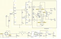
Finally a schematic:
Beware, this schematic is "sakuma" style, that is Input transformer with 1:2 stepup and interstage with 1:2 stepup, hard to get the right transformers for that, mine S&B specials with 80% Nickel Cores. No electrolytic capacitors either.
Output stage switchable 45/2A3/300B (heater windings switched series/parallel, cathode R switched). Biasing and DC balnce is a little unusual. The main PSU is 20uF MKP -> choke -> 40uF MKP (several small cap's in parallel). I used AC heaters as I ran out of space and voltage on the windings.
Sayonara
Taffi said:I DO have some very high quality Ansar SPX 47uF+47UF/550V laying around, but since they are so big I have not figured out where to place them yet.
Well, if you want some ideas, here is what I did using the same chassis etc...:
An externally hosted image should be here but it was not working when we last tested it.
An externally hosted image should be here but it was not working when we last tested it.
An externally hosted image should be here but it was not working when we last tested it.
Finally a schematic:
An externally hosted image should be here but it was not working when we last tested it.
Beware, this schematic is "sakuma" style, that is Input transformer with 1:2 stepup and interstage with 1:2 stepup, hard to get the right transformers for that, mine S&B specials with 80% Nickel Cores. No electrolytic capacitors either.
Output stage switchable 45/2A3/300B (heater windings switched series/parallel, cathode R switched). Biasing and DC balnce is a little unusual. The main PSU is 20uF MKP -> choke -> 40uF MKP (several small cap's in parallel). I used AC heaters as I ran out of space and voltage on the windings.
Sayonara
Kuei Yang Wang said:Konnichiwa
I just had a look at my records. It seems your Amp should have a 70V AC winding on the mains transformer for the fixed bias option.
Found it.
Fine. Hopefully I can find a bridge rectifier laying around somewhere.This means you can use a simple bridge rectifier and get around 100V Supply. Using a 220uF/450V filter capacitor will do splendidly.
What current rating do I need?
You mean on the power pcb, right?If I remember correctly, R20 & R24 are on the actual Driver PCB with the 290V PSU feed taken to the driver PCB from the PSU PCB. You simply connect the negative side of your new 100V supply to the 290V point
and take the positive side to the Driver PCB, feeding the driver PCB around 400V. That gives the whole driver circuit more voltage headroom and linearity.
Think I got it.All else you would need to do in that case is to change R20 to 1K and R24 to 2K2, R9 becomes 68K and R1 gets adjusted in circuit to give around 80-85V on the Anode of the Input Valve (V1) and then use a 6CG7 or 12AU7 (electrically similar except Heater connection and heater current/voltage) as first stage.
Which value should I use as starting point for R1?
In case I fail to get hold of a 6CG7 I DO have many 12AU7 laying around (Mullard, Brimar, Siemens, Sylvania).
Should I also go back to 47K and 51K plateresistors (should they really have different value?) and 15K common cathode resistor for the 5687's?
Well I have done so in the schematic attached, but if I have not got it all wrong this should give a current thru each of the halves of the 5687 of only 2,5mA.
Attachments
Holy ****!Kuei Yang Wang said:Konnichiwa,
Well, if you want some ideas, here is what I did using the same chassis etc...:
Sayonara

I think I shall wait a for a while before I try something like that.
But I do also have some ITSE810 laying around.....
Btw my Ansar caps are way bigger than that.
I would guess 60x100mm each so it would be nearly impossible to fit them inside.
Konnichiwa,
Well, around 30mA If or higher... So basically anything at hand, 0.5-1A at leats 200V.
The version i had has R20 & R24 on the Driver PCB, together with C4/5.
Almost. Your bridge is the wrong polarity, this way you'll let the smoke out of the Capacitors and Diodes....
470R.
if you change them anyway, ideally use 51K Anode resistors and 18K common cathode R.
It's close enough for government work, except the second bridge polarity.
As for the 5687 sections, you will be running 190V/2.5mA/51K load. Just draw in the loadline for fun. You get a fairly linear swing of nearly 300V P-P on the Anode theoretically (practically you are out of voltage at around 200V P-P as the +B is still a little low).
Check the way Kondo San (Audio Note Japan) runs the 5687 as Voltage Amplifier.
Anyway, you don't have to take my word. Simply change the Anode resistors to 15K and the cathode R to 6K2 and listen for yourself. That runs 8mA per section. Or just look at the loadlines....
Sayonara
PS, another Kondo trick I find works great, put a 2n2 - 4n7 silver mica (or silver foil) capacitor across the input stage cathode resistor. Try it.
Taffi said:Fine. Hopefully I can find a bridge rectifier laying around somewhere. What current rating do I need?
Well, around 30mA If or higher... So basically anything at hand, 0.5-1A at leats 200V.
Taffi said:You mean on the power pcb, right?
The version i had has R20 & R24 on the Driver PCB, together with C4/5.
Taffi said:Think I got it.
Almost. Your bridge is the wrong polarity, this way you'll let the smoke out of the Capacitors and Diodes....
Taffi said:Which value should I use as starting point for R1?
470R.
Taffi said:Should I then go back to 47K and 51K plateresistors (should they really have different value?) and 15K common cathode resistor for the 5687's?
if you change them anyway, ideally use 51K Anode resistors and 18K common cathode R.
Taffi said:Well I have done so in the schematic attached, but if I have not got it all wrong this should give a current thru each of the halves of the 5687 of only 2,5mA.
It's close enough for government work, except the second bridge polarity.
As for the 5687 sections, you will be running 190V/2.5mA/51K load. Just draw in the loadline for fun. You get a fairly linear swing of nearly 300V P-P on the Anode theoretically (practically you are out of voltage at around 200V P-P as the +B is still a little low).
Check the way Kondo San (Audio Note Japan) runs the 5687 as Voltage Amplifier.
Anyway, you don't have to take my word. Simply change the Anode resistors to 15K and the cathode R to 6K2 and listen for yourself. That runs 8mA per section. Or just look at the loadlines....
Sayonara
PS, another Kondo trick I find works great, put a 2n2 - 4n7 silver mica (or silver foil) capacitor across the input stage cathode resistor. Try it.
Konnichiwa,
Memory is hazy now, but I think I liked best GE "cleartop" 6CG7/6FQ7.
Sayonara
Taffi said:Any special brand of 6CG7 I should try to find (or any others that I absolutely NOT should buy)?
Memory is hazy now, but I think I liked best GE "cleartop" 6CG7/6FQ7.
Sayonara
Here is what the Norwegian dealer has to offer:
NEW
Ei Elite.....................................90,-
Ei Elite gold............................160,-
Golden Dragon..................... 125,-
GoldenDragon special...........175,- (Goldpins)
NOS
Westinghouse........................175,-
RCA........................................200,-
RCA Radiotron 50/60talls.......250,-
GE...........................................200,-
Since I just need one the price are not so important.
Think I should buy two different.
What do you recommend?
Konnichiwa,
Get one of the cheapest for testing and then carefully select the expensive ones. Read around. As one Cary Linestage used 6CG7/6DJ8 interchangable you can find quite a bit of coverage on this if you search.
Sayonara
Taffi said:What do you recommend?
Get one of the cheapest for testing and then carefully select the expensive ones. Read around. As one Cary Linestage used 6CG7/6DJ8 interchangable you can find quite a bit of coverage on this if you search.
Sayonara
Thanks Andy!andyjevans said:How do you find getting componants in your part of Norway? I used to live in Tonsberg, and I mostly ordered from Britain for the variety and lower prices. Do you pay customs duty on items that are sent to you - how do you get audio stuff? Lukke til, Andy
Just one mistake.
It spells "lykke til" (but please do not correct my English
Regarding supply of components it is no problem getting things sent in Norway and Motron in Norway do stock many different tubes (both new and NOS). But Motron is very expensive on the most popular tubes so in that case I have other suppliers from all over the world.
And yes, we have to pay 25% tax on what are being sent to us from abroad and because of this many used to get false invoices (which of course are illegal).
But if I have not misunderstood it is now free of tax if the amount are under Nkr 1.000,-.
Many thinks this is very good, but personally I am not sure.
I finds it unfair to people who are trying to run a business and make a living in Norway when their foreign competitors could sell to the same customers without having to charge 25%.
This makes is nearly impossible to compete.....
- Status
- This old topic is closed. If you want to reopen this topic, contact a moderator using the "Report Post" button.
- Home
- Amplifiers
- Tubes / Valves
- ECC88/5687/2A3 amp voltages