I meant a thermal switch, you'r either going to have to protect the circuit against too much heat, which you can do with a temperature sensor circuit. There are however switches that are used in industry that go open at a specified temperature.
The Other option would be to use a heatsink sufficiently large to be able to cool the worst case power dissipation of the circuit, with some margin because you live in a hot climate.
I suspect you want around 180-200V from a 250V supply (Rectified 230V) so your normal dissipation is going to be : ((VIN-VOUT)*Current out)+ (Vout*(Shunt CCS current-output current)
For Line input variations you have to take into account that your mains might be 10% high.
I'm late to the party as-usual. About two decades ago, I built a very similar headphone amp. It uses a triode voltage amp based on a 12AU7, and a 6080 as a cathod follower. But I put a bit of feedback around the whole gain stage, which reduces distortion and more importantly lowers the output impedance. Plus it gets the circuit gain in a more comfortable region.
Here's the schematic and a couple pictures:
http://quadesl.com/diyaudio/tube_hp.pdf
http://quadesl.com/diyaudio/IMG_8033.jpg
http://quadesl.com/diyaudio/IMG_8034.jpg
The astute will notice that the power supply is super sleazy in that I took a dual primary toroid power transformer and used one of the primaries as a b+ winding. Don't try this at home, kids...
I'm not really adding much to the discussion, other than to suggest that you try some feedback around the circuits described above.
Sheldon
Thanks to share your experience.
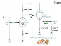
Attached one pic just for fun. Works like a charm without hum.
It's OK each 7N7 only draws 1.33mA, I measured 133 volts across 100K plate load resistor?
What cap value to bypass the cathode resistor of 7N7, or better how to calculate?
It's OK?
On line bypass capacitor calculator gives me min. 13uF for 2K2 of cathode resistors with a corner frecuency of 60Hz, it's OK?
Attached one pic just for fun. Works like a charm without hum.
It's OK each 7N7 only draws 1.33mA, I measured 133 volts across 100K plate load resistor?
You can check the datasheet for the 6SN7 for reccomended anode grid leak and cathode resistances. @ 150V B+ The anode will then hopefully bias up at +80V with respect to ground. Then you can choose whether to have the tube directly coupled to the 6080 or to include a RC bias circuit.
Edit i just checked for you, 2K2 cathode resistor, 100K anode resistor, 100K grid leak (Or the direct coupled pot like you show in your drawing. Gain will be about 24-28. You can and should bypass the cathode resistor
What cap value to bypass the cathode resistor of 7N7, or better how to calculate?
It's OK each 7N7 only draws 1.33mA, I measured 133 volts across 100K plate load resistor?
It's OK?
What cap value to bypass the cathode resistor of 7N7, or better how to calculate?
On line bypass capacitor calculator gives me min. 13uF for 2K2 of cathode resistors with a corner frecuency of 60Hz, it's OK?
Attachments
![WP_20171103_001[1].jpg](/community/data/attachments/594/594979-c627a938057b9f80b5658e1088394354.jpg)
This way you can dc couple both tubes and stay within a reasonable op for the 6sn7..i do not understand the reason behind r3,r31
- Status
- This old topic is closed. If you want to reopen this topic, contact a moderator using the "Report Post" button.
- Home
- Amplifiers
- Tubes / Valves
- 6AS7 OTL headphone amplifier